


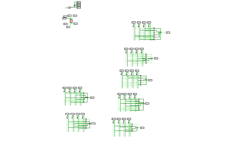
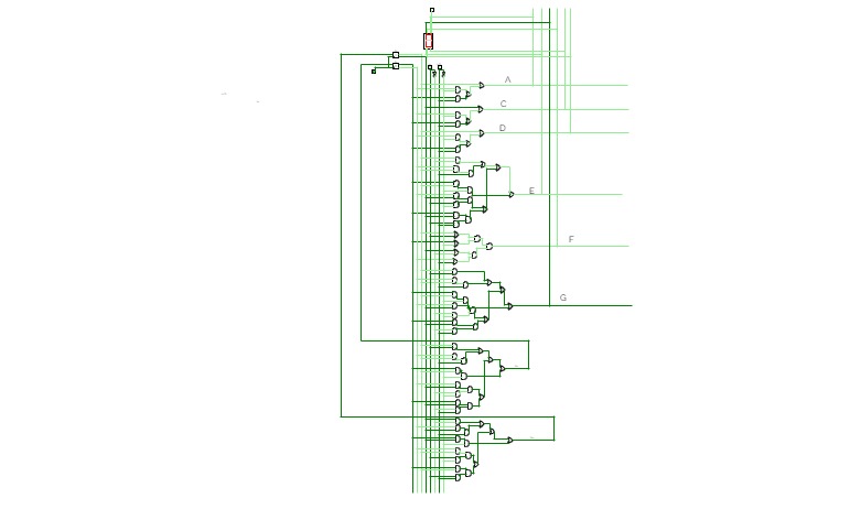
7 segment decoder
7 segment decoderJohnson counter
Johnson counterd ff asynchron zahler 3 bit
d ff asynchron zahler 3 bitjk ff counter synchronous
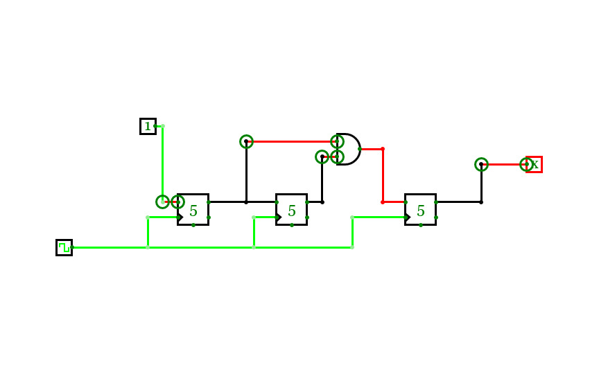
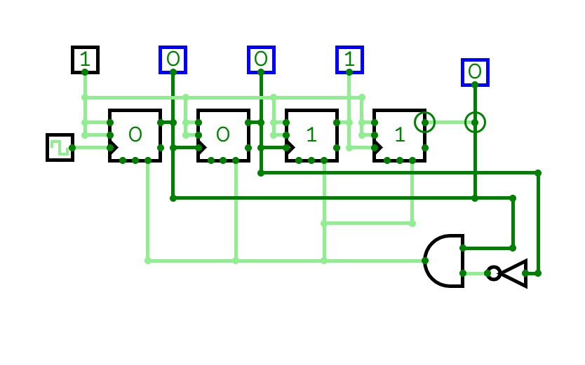
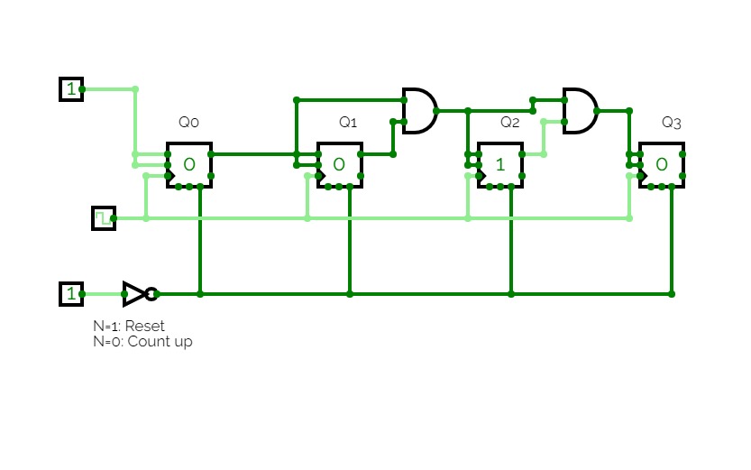
jk ff counter synchronous3bit jk synchronous counter. it counts till 5 then resets if oyuwant to remove the reset just disconnect the async reset .

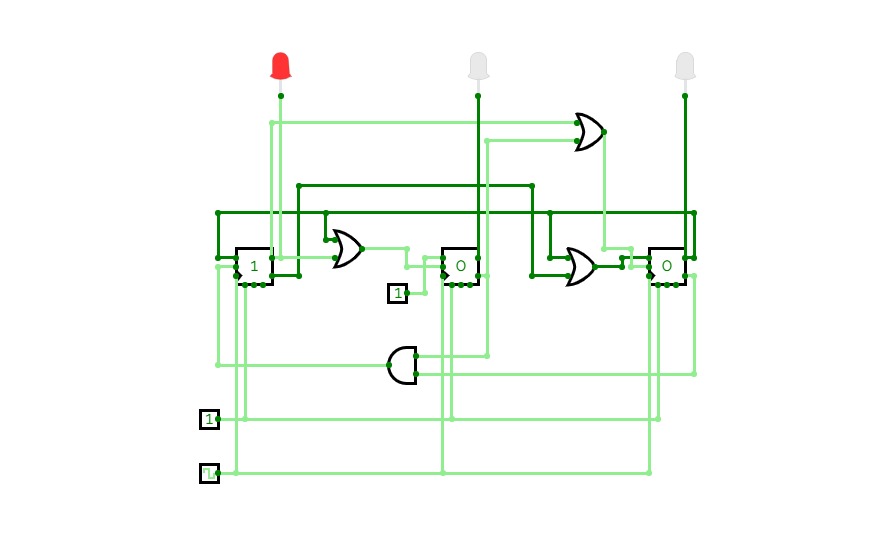
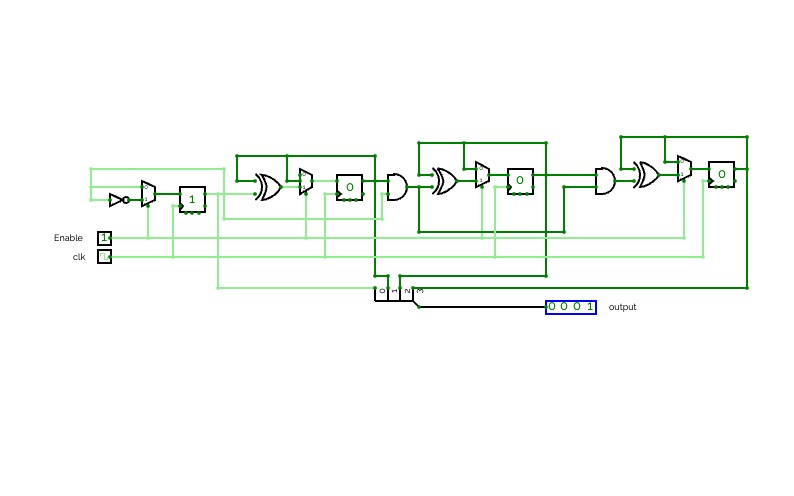
Decade Counter
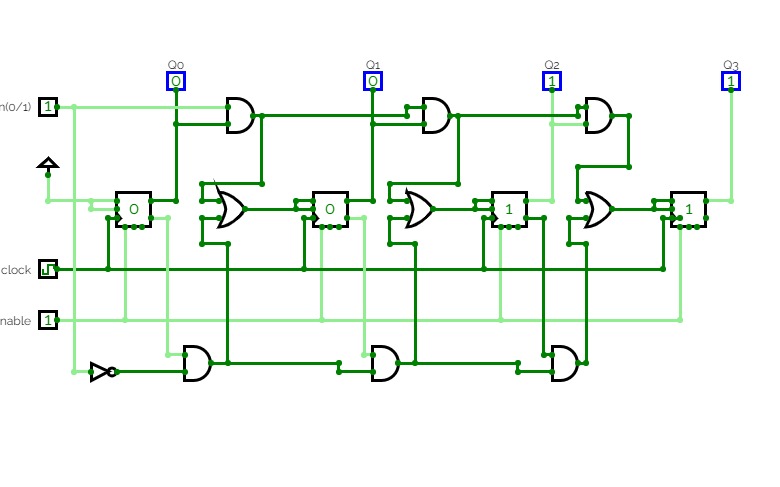
Decade CounterExperiment No 10: Implement a decade counter using basic gates.
Done by:
Saranga K. Mahanta
Scholar Id: 18-14-038
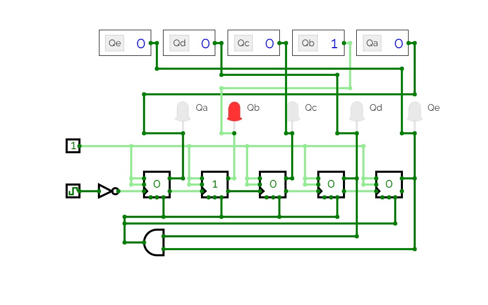
Johnson Counter
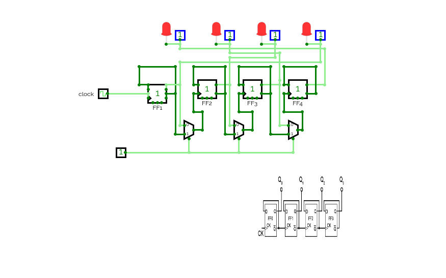
Johnson CounterDone by:
Saranga K. Mahanta
18-14-038

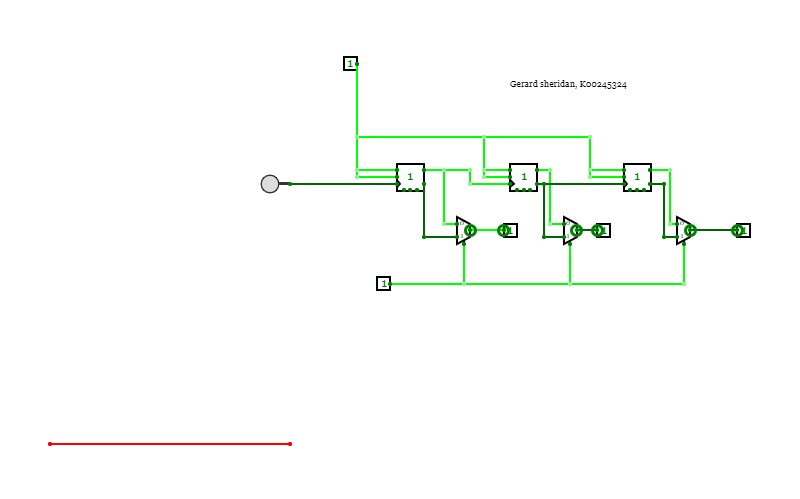
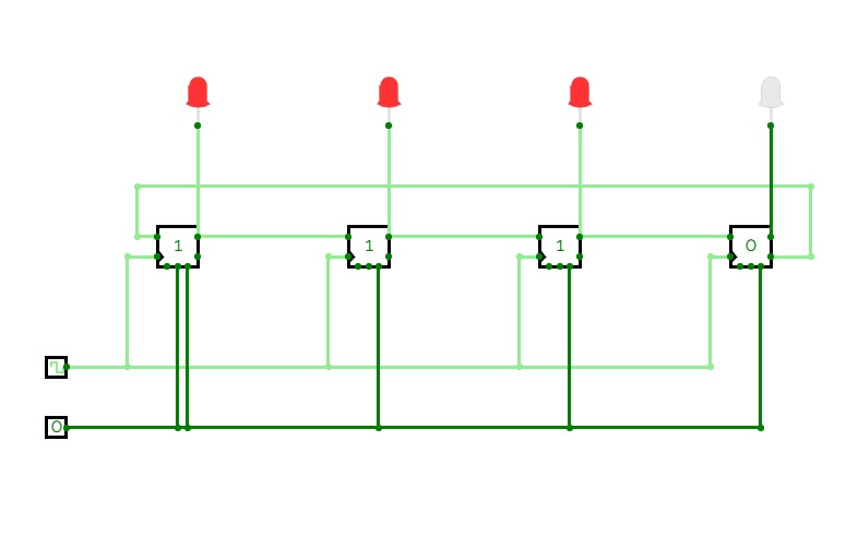
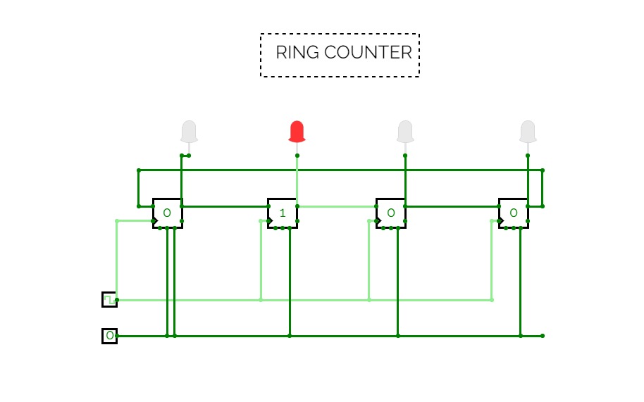
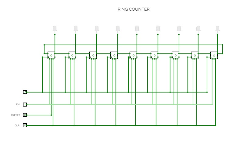
ring counter
ring counter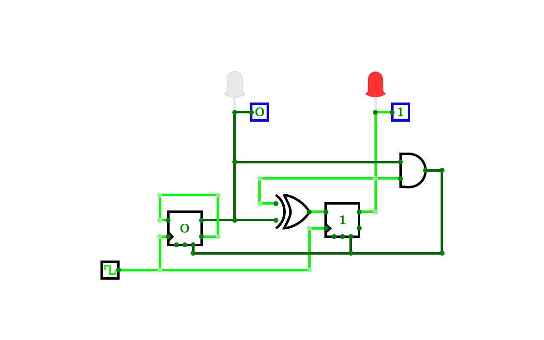
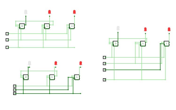
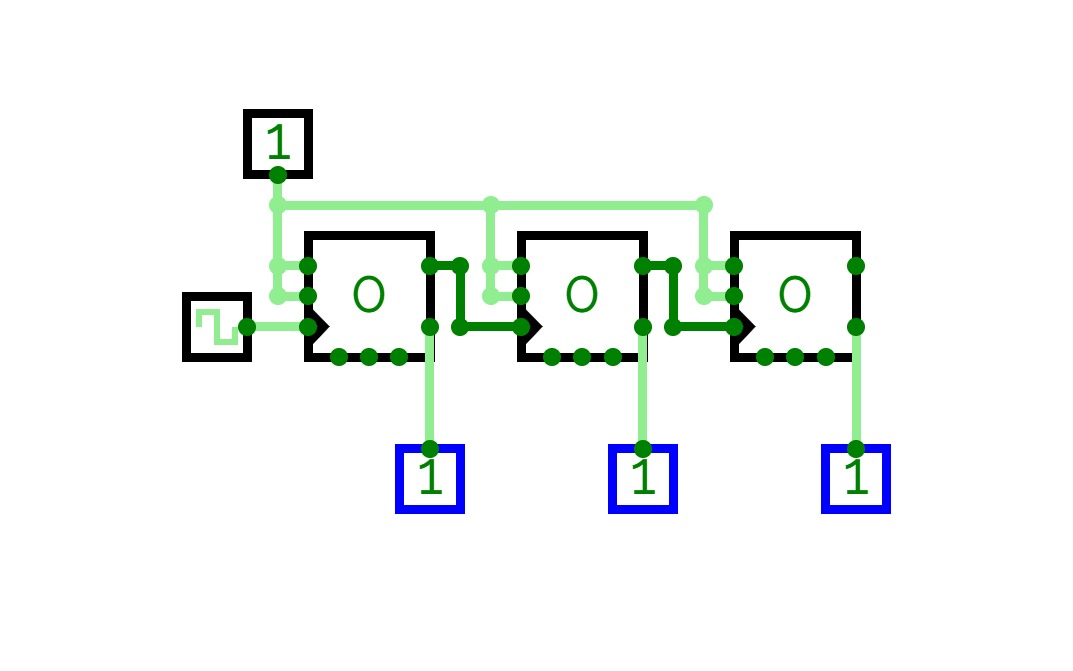
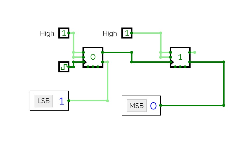
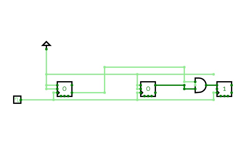
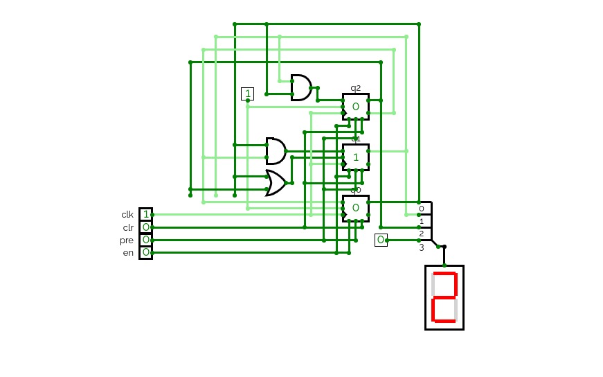
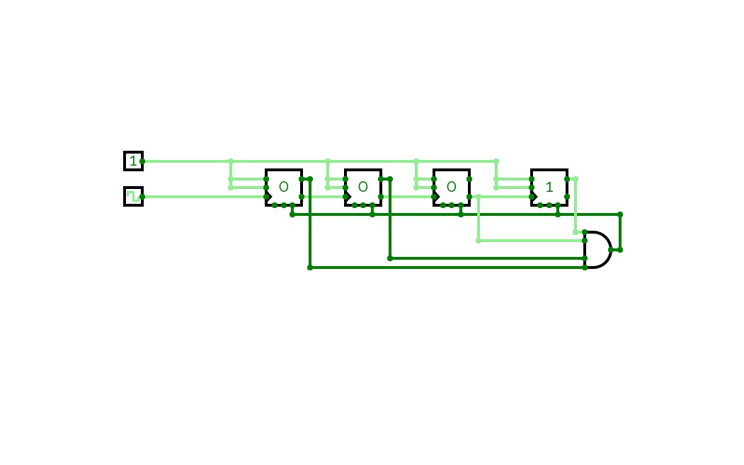
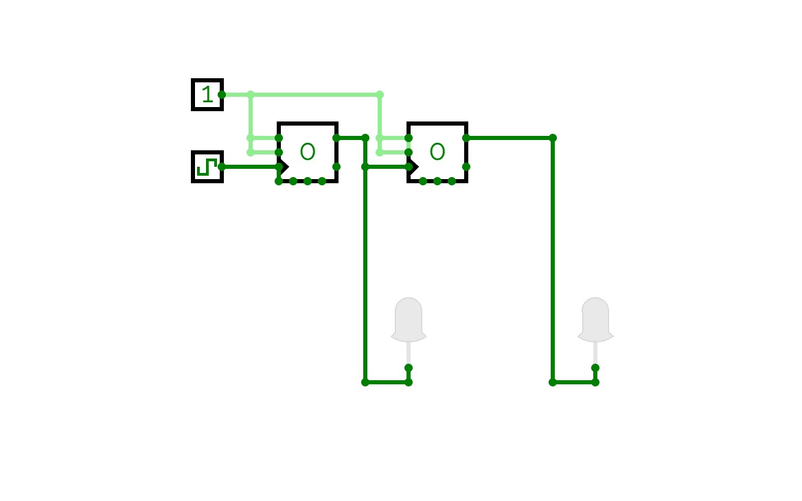
2-bit counter, limited to 3 numbers (0,1,2)
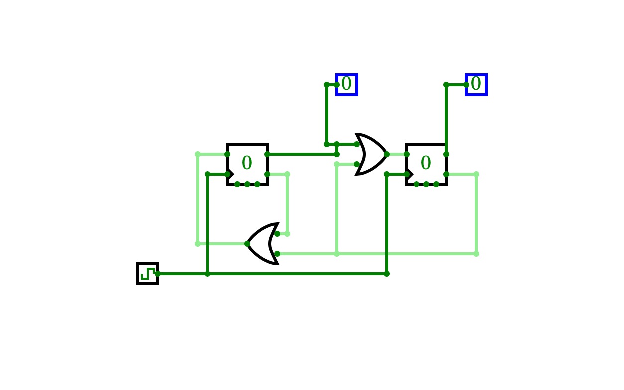
2-bit counter, limited to 3 numbers (0,1,2)This is a 2-bit counter. 2-bit counters normally can count 4 numbers: 0, 1, 2, 3. However, this circuit counts up to 2 and resets at 3. This can be scaled by adding more D flip-flops and setting the And gate at the location you want the count to stop at. You can also set a starting number in a similar fashion. This can be modified to a synchronous 2-bit counter using JK flip flops.
3 bit counter
3 bit counter3 bit counter
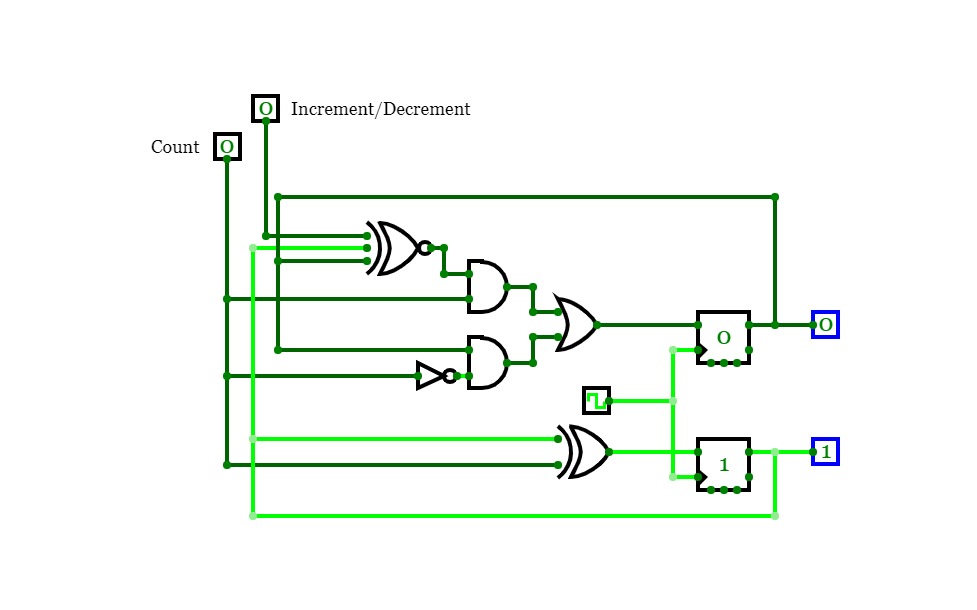
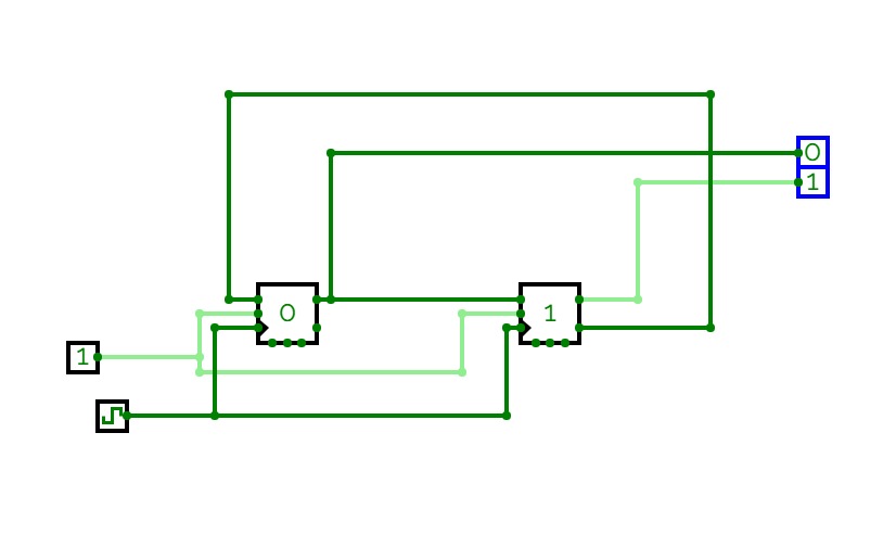
2-Bit Counter (Up and Down)
2-Bit Counter (Up and Down)A 2-bit counter that counts from 0 to 3! :D
Set "Count" to 1 to start counting and set it to 0 to pause the counter. Set "Increment/Decrement" to 1 to count up and 0 to count down.
Counter
Counter
Automatic Packaging system
Automatic Packaging system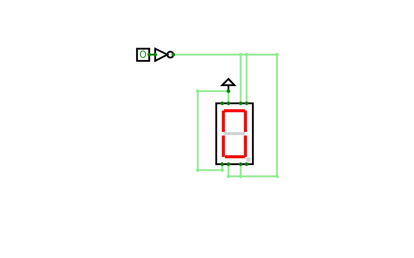
example project
example project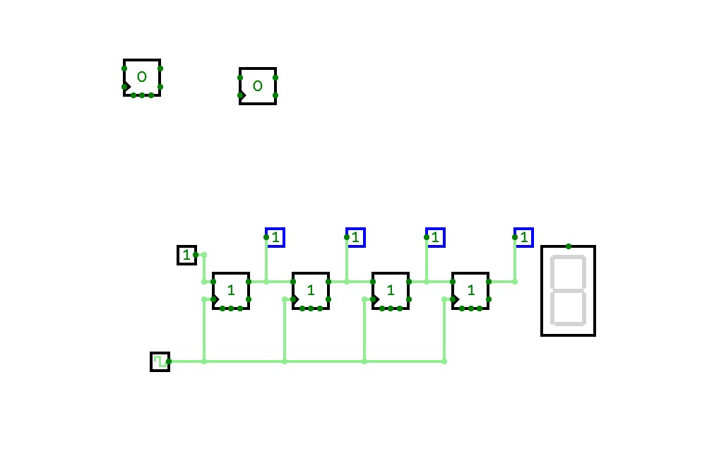
EDUCA
EDUCA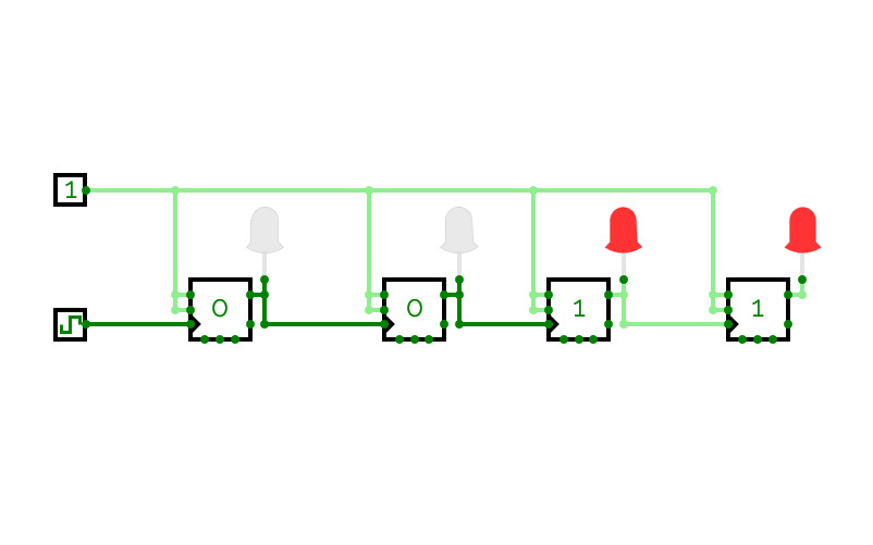
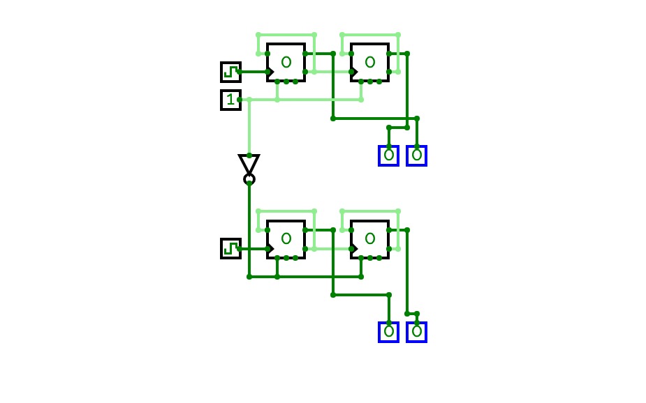
Asynchronní čítač 4 bit čítající dolů
Asynchronní čítač 4 bit čítající dolů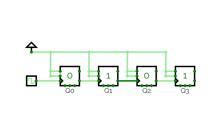
4 bit Asynchronous Counter
4 bit Asynchronous Counter4 bit Asynchronous Counter using JK FlipFlops
Clock and Counters
Clock and Counters
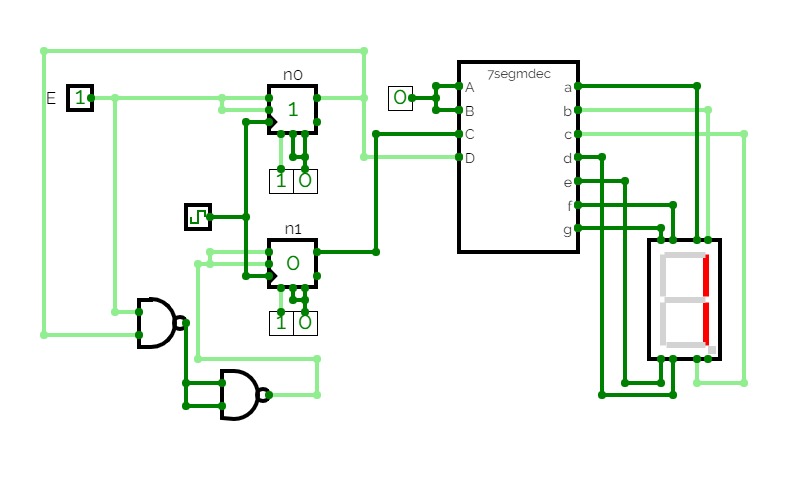
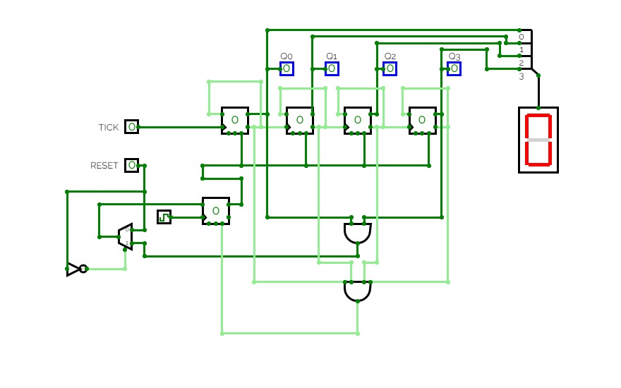
0-7 counter 7seg display
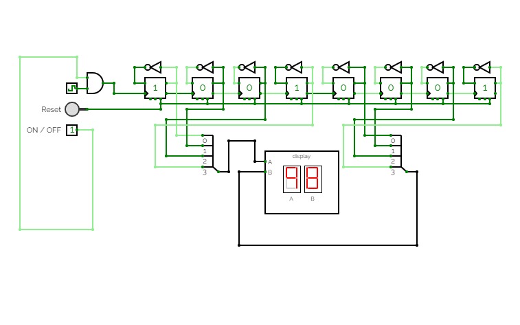
0-7 counter 7seg displayit counts.
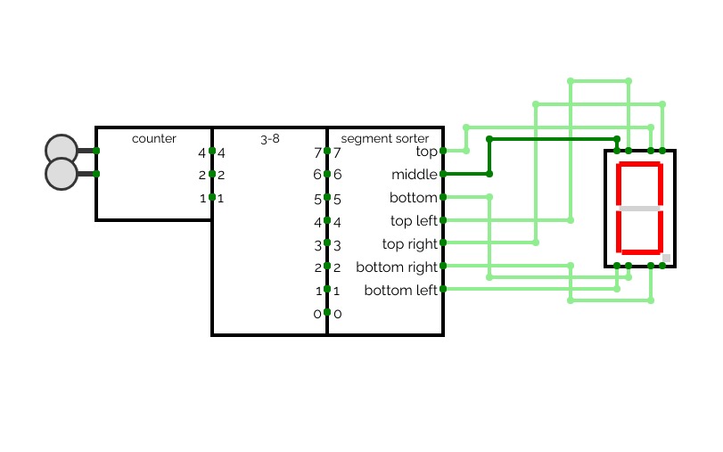
0-7 counter 7seg display
0-7 counter 7seg displayit counts
decade counter
decade counter
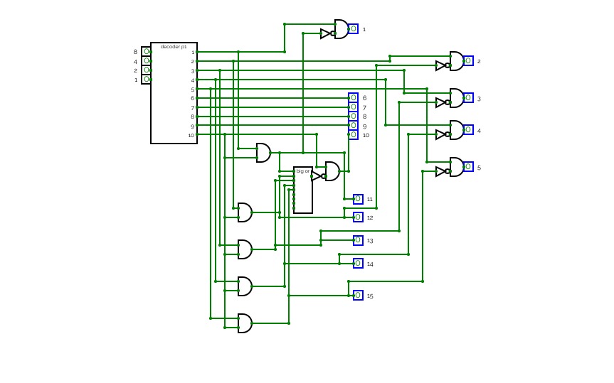
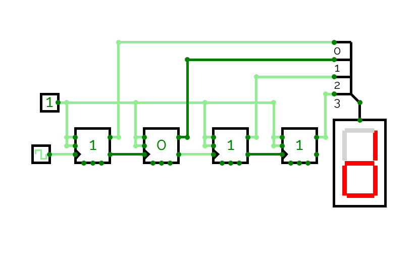
4 bit 7 segment display counter
4 bit 7 segment display counterit does what it says on the tin.
edit: the 13 is broken, but when I go in to edit everything breaks so :\ I'm pretty sure it's because I hooked up the 13 to the bottom left node in the "decoder4display"
edit: I went in to check and that is in fact the issue. I still have no clue wtf is wrong with the "decoder p1", as I changed literally nothing, but apparently I messed up. someone, please take a look at it and see what went wrong bc I really don't have any idea.
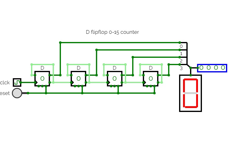
D flipflop mod 16 counter
D flipflop mod 16 counter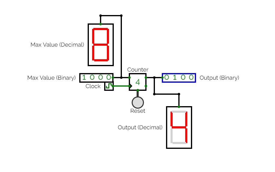

Counter
CounterA completely original (4-bit) counter I made.
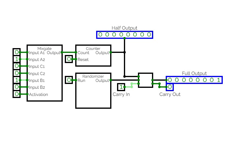
Subcircuit Test
Subcircuit TestMy first experiment with Subcircuits.
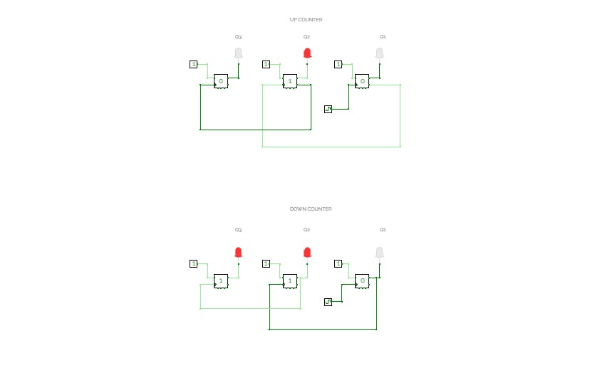
Up and Down Asynchronous Counter
Up and Down Asynchronous Counter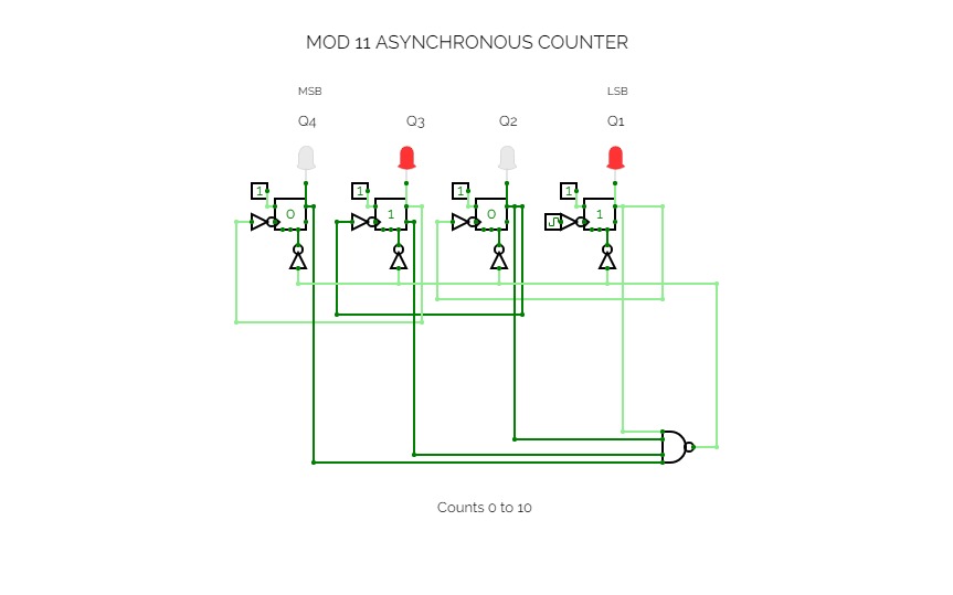
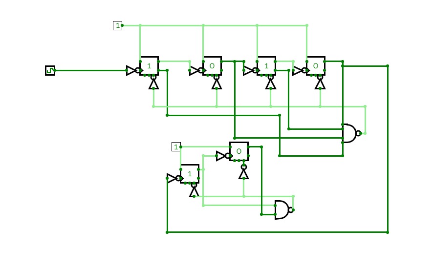
MOD 11 ASYNCHRONOUS COUNTER
MOD 11 ASYNCHRONOUS COUNTERIn this MOD 11 counter, it counts 0 to 10. i.e from 0000 to 1010, then it repeats itself. For 4 bits, 4 counters are required. Here -ve edge triggered T flipflop is taken.
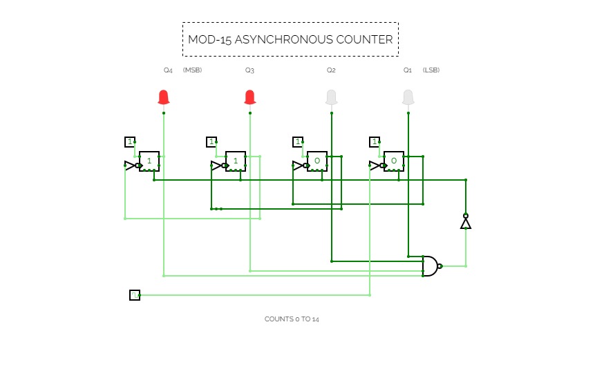
MOD-15 Counter
MOD-15 Counter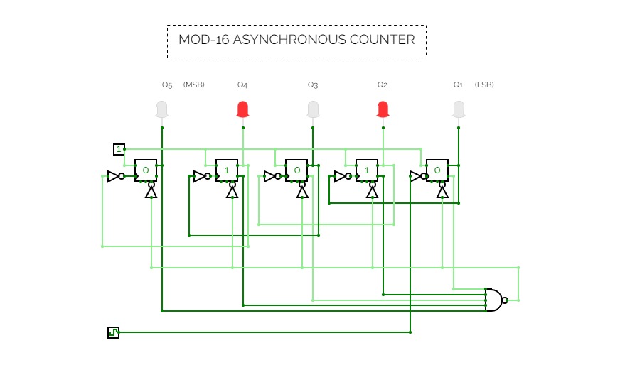
MOD-16 Counter
MOD-16 Counter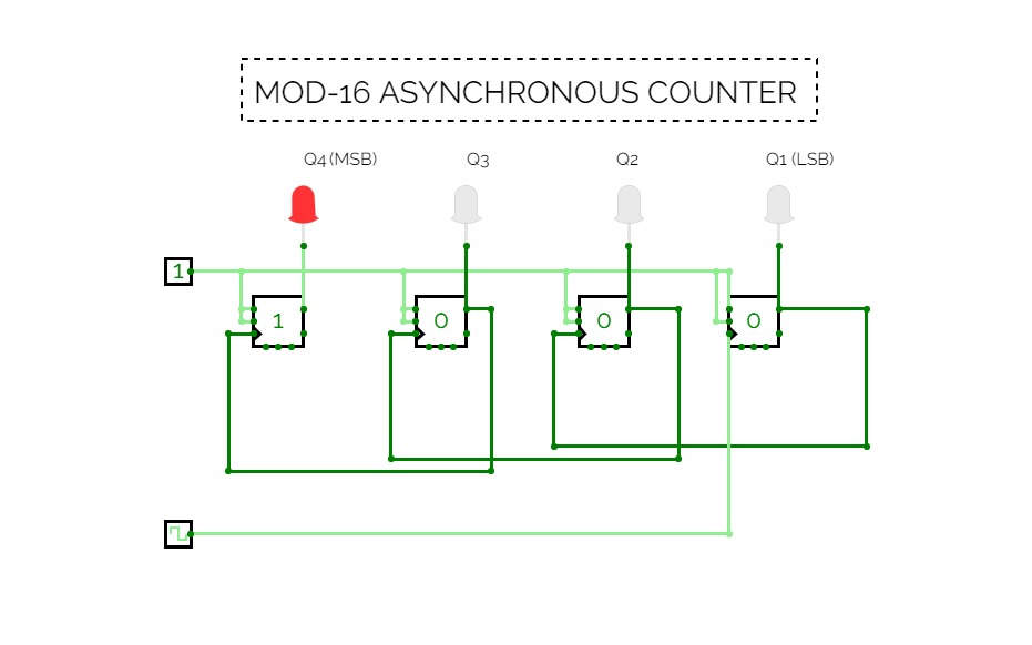
Johnson Counter
Johnson Counter

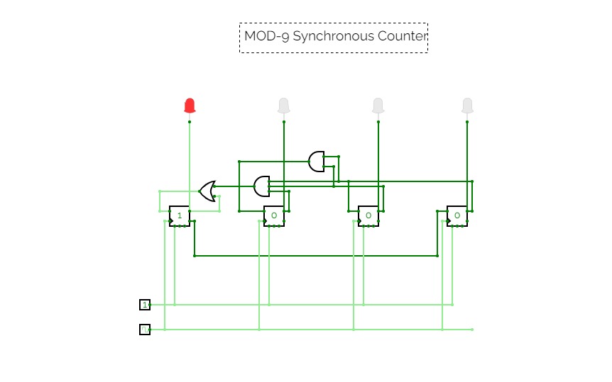
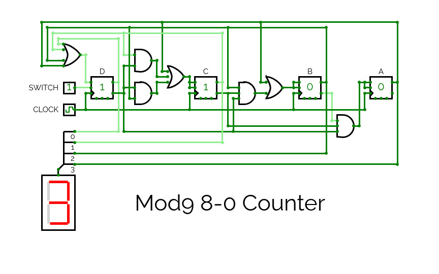
MOD-9 Synchronous Counter
MOD-9 Synchronous CounterTA = QA + QB.QC.QD; TB = QC.QD; TC = QD; TD = QA'

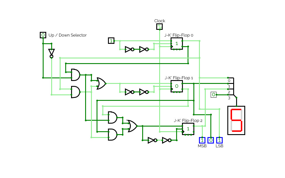
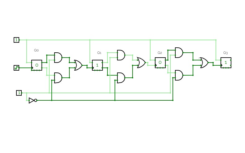
4 bit synch up/down counter
4 bit synch up/down counter4-bit synchronous counter created using JK flip flops where mode, M=0 is the up counter and M=1 is the down counter.
7 Segment Display Hexa
7 Segment Display Hexa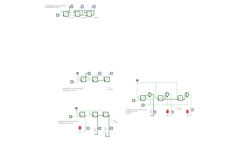
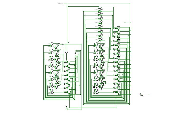
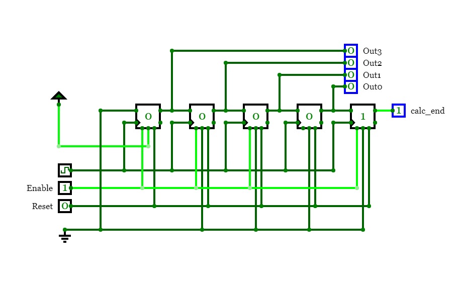
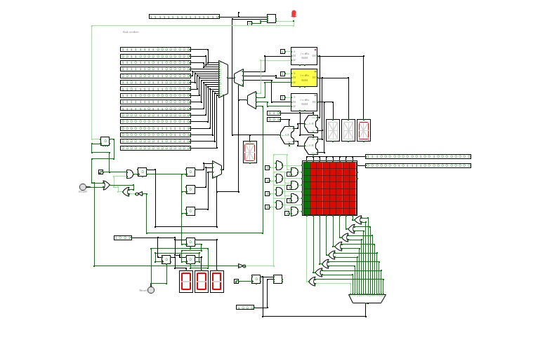
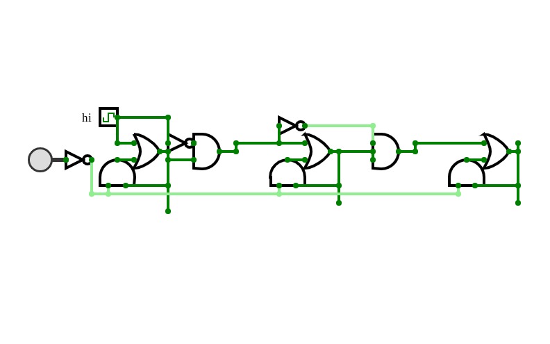
A multiplication circuit designed to multiply two 8-bit numbers, creating a 16-bit output. The values are unsigned, and input into two locations in a currently unconventional way. The output is stored in the flip-flop array to the right. The button at the top starts or resets the program.
-ve Trigger Counter Mod 24
-ve Trigger Counter Mod 24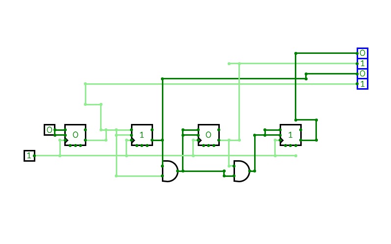

.png)
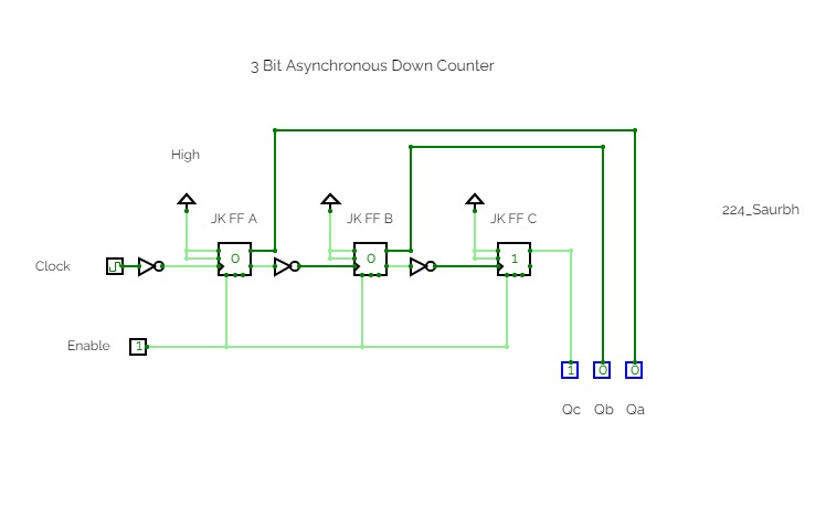
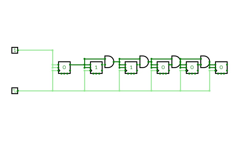
3 Bit Asynchronous Down Counter
3 Bit Asynchronous Down Counter3 Bit Asynchronous Down Counter

JK Flipflop falling
JK Flipflop falling
count4
count44 bit Asynchronous counter

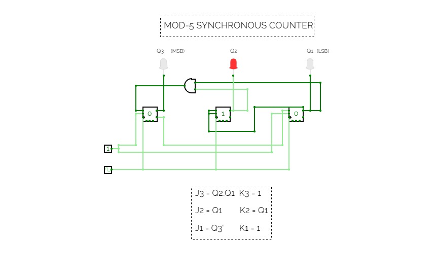
5-mod counter
5-mod counter
Counter mod 5 - Flip Flop JK
Counter mod 5 - Flip Flop JKExample of counter mod 5 made with flip flop JK
Counters
Counters
A181647_Q11
A181647_Q11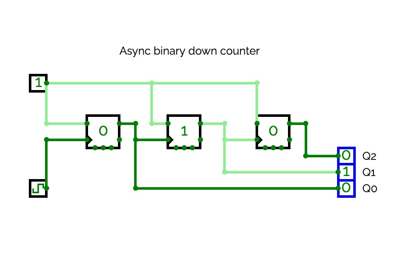
Async binary down counter
Async binary down counter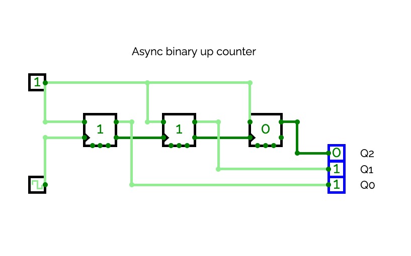
Async binary up counter
Async binary up counter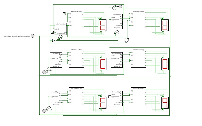
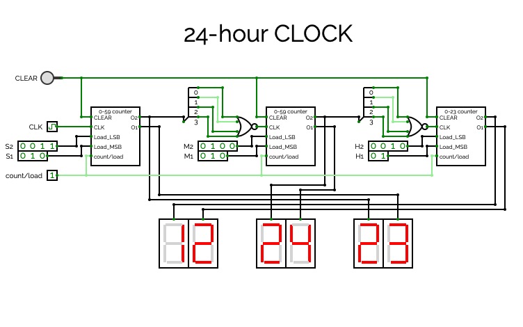
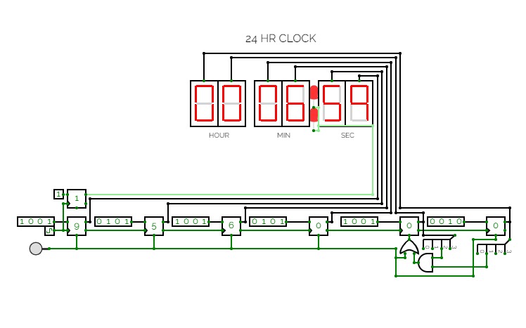
12hr digiClock
12hr digiClockThere's several buttons in the circuit. If you figure out what those do, the laws of time of this circuit's universe are yours to behold.
Note to future me to fix the following bug (if it even exists in the real world due to propagation delay).
The set 1 function of #2 works in the sub-circuit but fails to work for the output pulse in the main circuit. This is troubling to say the least. So I've decided to change hour 12:00 to 00:00.
4-bit asyncronous counter
4-bit asyncronous counter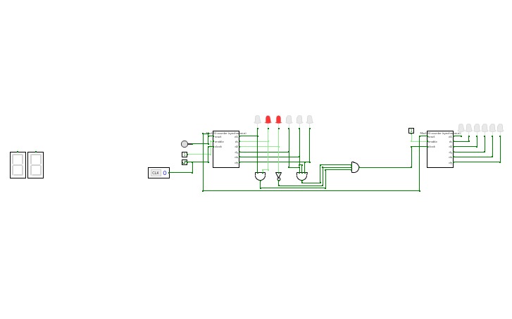
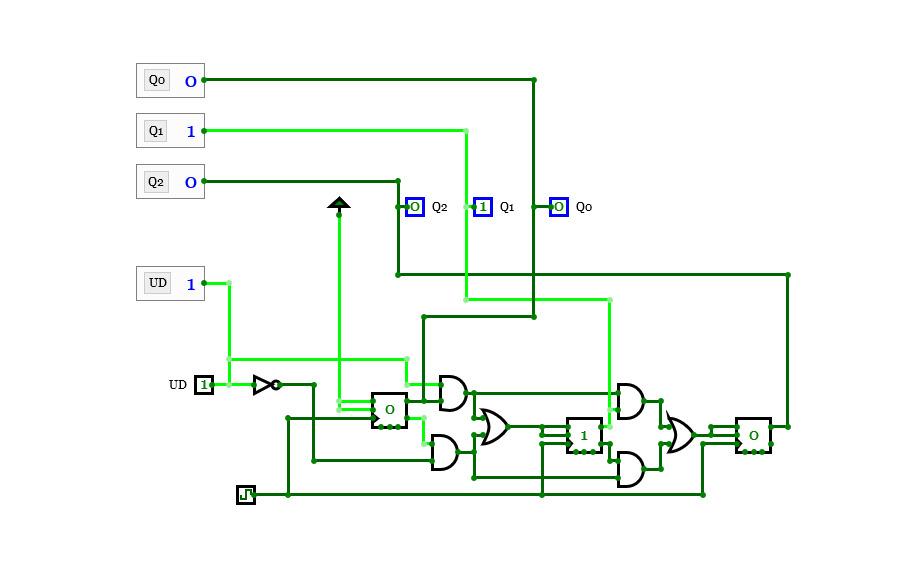
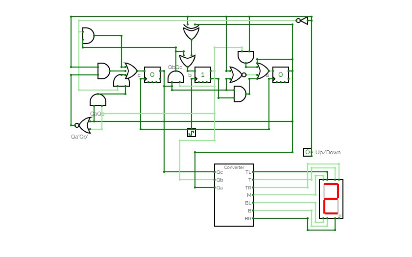
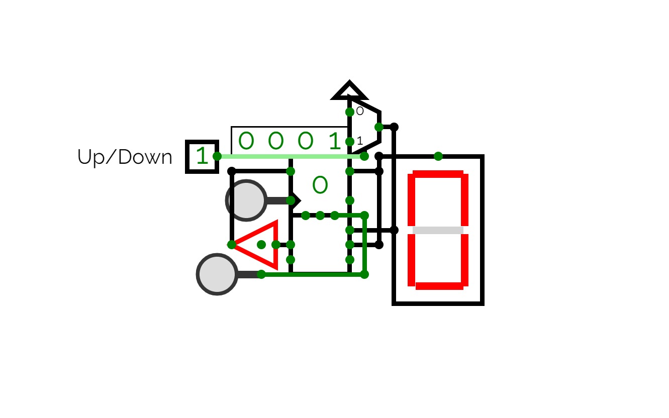
UpDownCounter
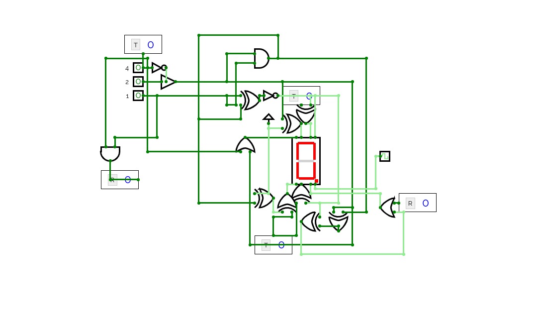
UpDownCounterVisualizing advanced counter with 7 segment display
U/D stands for UP/DOWN
M :
if the counter is in position 00 when the control signals change to 10 the counter must remain in position 00
if the counter is in position 11 when the control signals change to 11 the counter must remain in position 11

counter 4-bit JK-trg
counter 4-bit JK-trg4-bit simple counter based on JK-flip-flop

64 Counter With JK (no reverse)
64 Counter With JK (no reverse)
Contador de 2 bits
Contador de 2 bits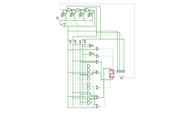
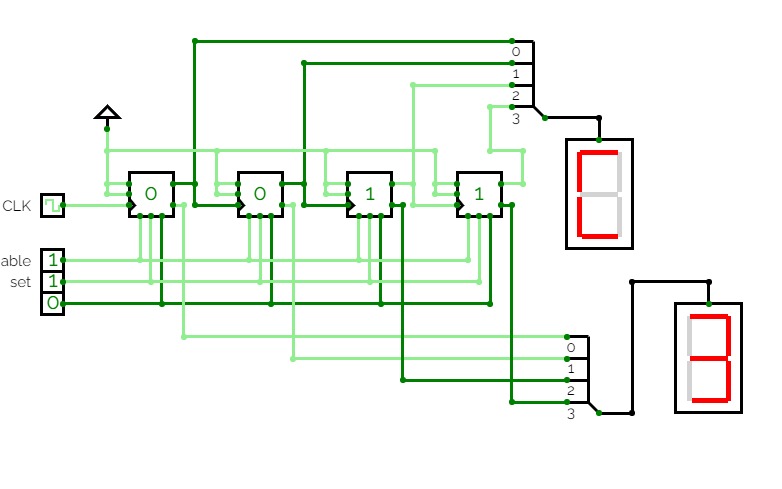
Synchronous BCD counter to Seven Segment Display
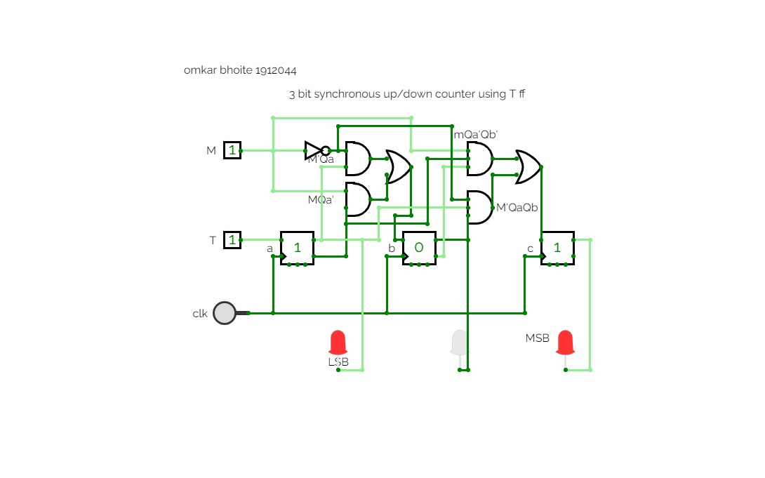
Synchronous BCD counter to Seven Segment DisplayThis is a "Synchronous BCD Counter To Seven Segment Decoder" made using T flip flop .
Firstly, the counter is made using T flipflop and then its output i.e(count) is converted to digital using Seven Segment Decoder
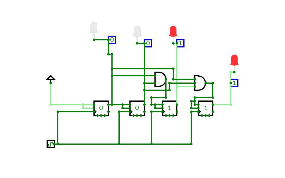

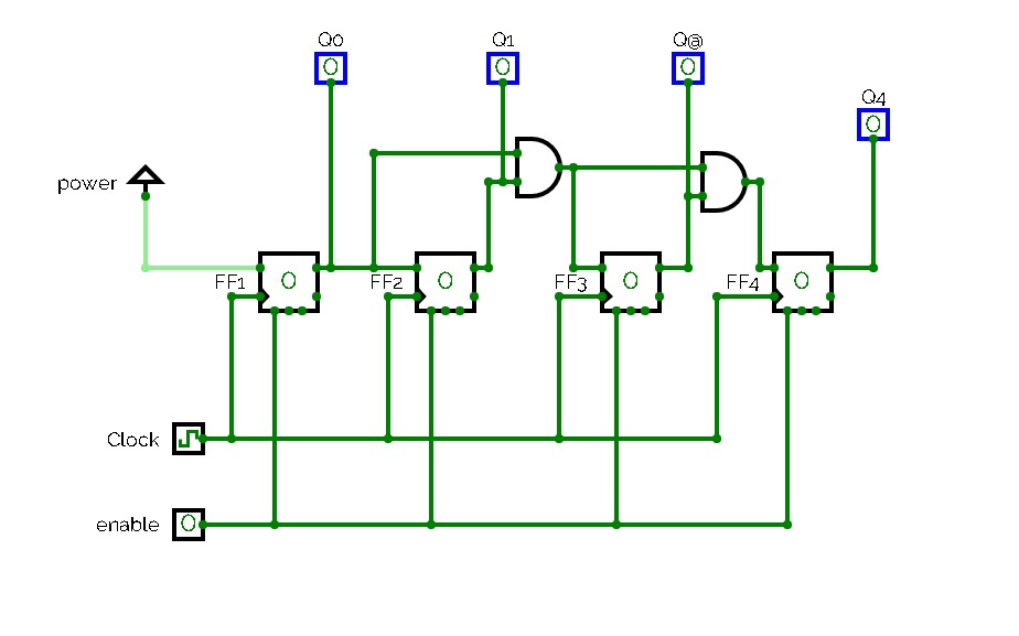
4 Bit Synchronous Counter
4 Bit Synchronous CounterHere is a full circuit diagram of 4-bit Synchronous Counter.
Feel free to contact me for any further concern.
Thank you.
Regards,
Noman Ali.
Up_Down_Combo
Up_Down_ComboNULL
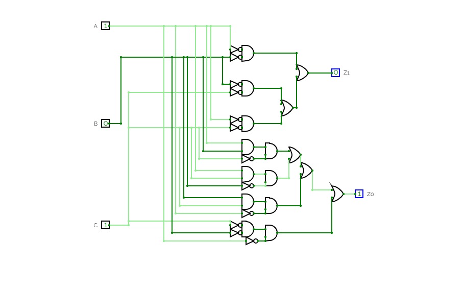
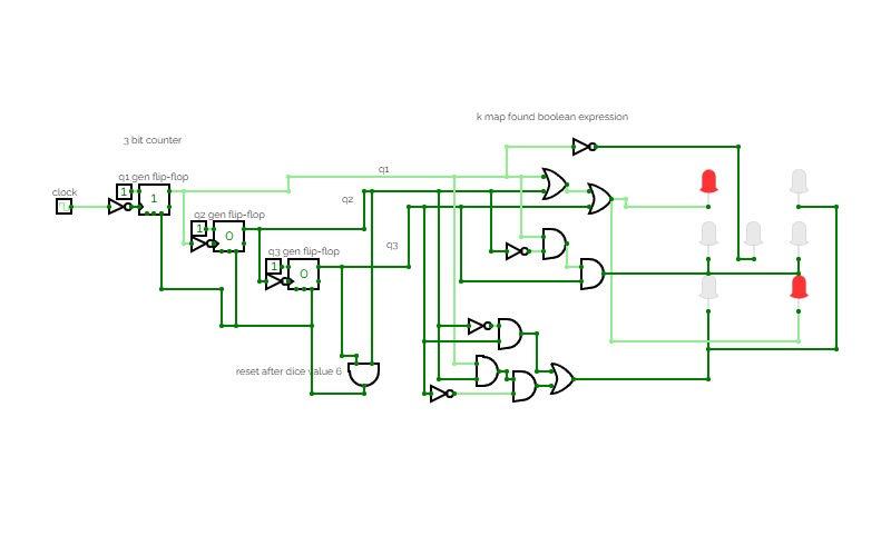
3 way traffic lights
3 way traffic lightsIn the 3 bit counter the last 2 set the traffic lights in 3 possible states (1 green for each path) while the 1st flipflop is used to provide the short duration yellow -> red state change (How it works in my country).
All logical expression have been derived from k maps at specific states.
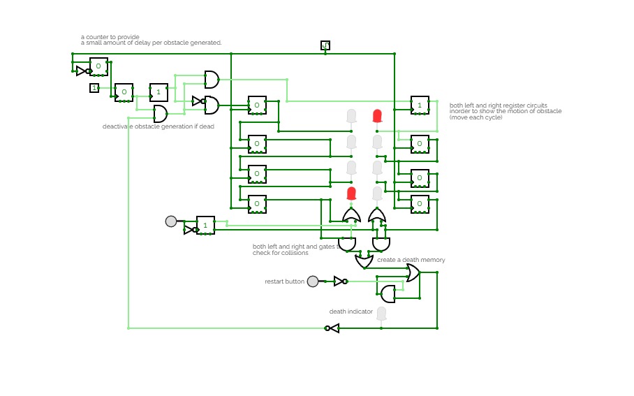
Use the button inorder to jump from left to right and vice vera and try avoiding the incoming obstacles.
If you collide with it you die and can restart using the restart button given at the bottom.
Change the difficulty by reducing the timing setting of the clock and good luck :D.
Gray Code Up Counter
Gray Code Up CounterMultiple variations of a 3-bit gray code up counter.
JK -> D -> D using NAND -> Decoder to Display
EDIT: Added BCD-to-7-Segment Sub Circuit
4 bites aszinkron fel/le számláló
4 bites aszinkron fel/le számláló4 bites aszinkron fel/le számláló/ 4 bits asynchronous up/down counter
4 bites szinkron számláló/4 bit synchronous counter with reset
4 bites szinkron számláló/4 bit synchronous counter with reset4 bites szinkron számláló/4 bit synchronous counter with reset
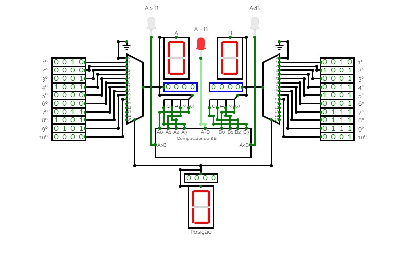

Comparador de 20 dígitos
Comparador de 20 dígitosCircuito criado visando prática aos estudos sobre Circuitos Combinacionais realizados na disciplina de Circuitos Digitais - Universidade Federal do Maranhão.

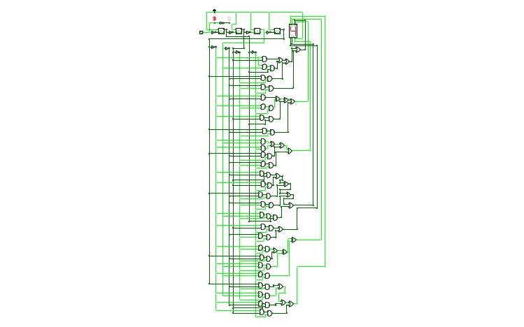
rixis combinox r1 cpu computer
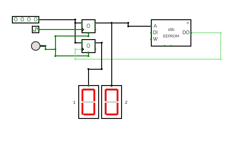
rixis combinox r1 cpu computerAbout the Combinox R1:
This is the third 16-bit CPU I have made. Its new name was inspired by the new combinational code. It is also my first computer to feature a graphics and base ten display. As a result of its brand new architecture, code, and clock it is much faster than my previous CPUs.
Directions for use:
Choose the desired EEPROM program and insert it into the slot. First press the "RESET" button. Now press the "ON" button and enjoy your program.
Descriptions of programs:
blank: A blank EEPROM to be coded.
count up forever: Counts up by one until it reaches 65,535 then loops back to 0.
2+2: adds 2+2 and displays the output to the number display
transfer from keyboard to display: Displays the ascii value of whatever key is being entered on the keyboard.
random noise: Displays random noise on the screen.
Fibonacci: calculates the Fibonacci sequence
Credits:
Sanderokian Stfetoneri - clock
Sanderokian Stfetoneri - 16 bit division


.jpg)
CTH-10 CPU
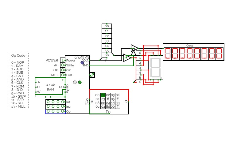
CTH-10 CPUThis is the CTH-10 CPU. By CrEePeRz24321. (most updated version of the CTH Series) This uses all binary to operate. First click on Power to start. Turn Op to 1 and double click the RAM. Then type in the Op code you want. Only put inputs and read outputs of the User Interface. Wait until the Red light turns Green then start. If you want to change operations, then turn Op to 1 and double click the RAM. Then type in the Op code you want. (If you use full screen, and it keeps on kicking you out when you type, click full screen and then look to the bottom right and press + or - and don't touch the full screen after that unless the RAM input kicks you out)
0 is No Operation - Inputs unavailable
1 is RAM - write the address into In1, write the number you want to store into In2 and press Write.
2 is ADD - write the first digit into In1, write the second digit into In2
3 is Subtract - write the first digit into In1, write the second digit into In2
4 is Counter - Inputs unavailable
5 is AND Gate - write the first digit into In1, write the second digit into In2
6 is a Clock - Inputs unavailable
7 is Accessing the ROM - Inputs unavailable
8 is Binary to Decimal converter
9 is Random Number - Inputs unavailable
10 is Not Gate - write the converting digit into In1
11 is Shift Right* - write the converting digit into In1, write the shift number into In2
12 is Shift Left* - write the converting digit into In1, write the shift number into In2
13 is Multiply - write the first digit into In1, write the second digit into In2
14 is Divide - write the first digit into In1, write the second digit into In2**
HALT is to halt operation
*when using shift the first 3 digits of Out will be nonfunctional
**when using divide the first 4 digits away from the CPU are remainders and the last 4 digits closest to the CPU are quotients.
(There is also a Computer version that doesn't get updated much.)
CTH-10
CTH-10This is the CTH-10 CPU. This uses all binary to operate. First click on Power to start. Turn Op to 1 and double click the RAM. Then type in the Op code you want. Only put inputs and read outputs of the User Interface. Wait until the Red light turns Green then start. If you want to change operations, then turn Op to 1 and double click the RAM. Then type in the Op code you want. (If you use full screen, and it keeps on kicking you out when you type, click full screen and then look to the bottom right and press + or - and don't touch the full screen after that unless the RAM input kicks you out)
0 is No Operation - Inputs unavailable
1 is RAM - write the address into In1, write the number you want to store into In2 and press Write.
2 is ADD - write the first digit into In1, write the second digit into In2
3 is Subtract - write the first digit into In1, write the second digit into In2
4 is Counter - Inputs unavailable
5 is AND Gate - write the first digit into In1, write the second digit into In2
6 is a Clock - Inputs unavailable
7 is Accessing the ROM - Inputs unavailable
8 is Binary to Decimal converter
9 is Random Number - Inputs unavailable
10 is Not Gate - write the converting digit into In1
11 is Shift Right* - write the converting digit into In1, write the shift number into In2
12 is Shift Left* - write the converting digit into In1, write the shift number into In2
13 is Multiply - write the first digit into In1, write the second digit into In2
HALT is to halt operation
*when using shift the first 3 digits of Out will be nonfunctional
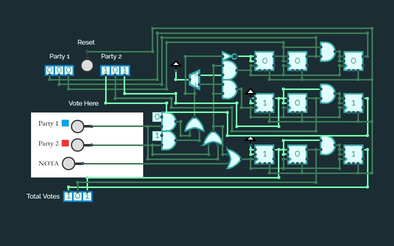
Electronic Voting Machine
Electronic Voting MachineSimulates a 2 party electronic voting system with an added feature of NOTA option for voters.
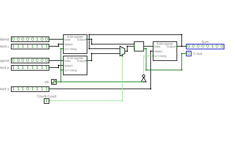
Adjustable 8-bit adder which either loads values from two different registers into an 8-bit adder or sequentially adds the current output value of the adder to the value stored in the first register. Practice for RAM unit application, register creation and organization, bit splitting and compression, and sequential logic.


Sequential Practice 4
Sequential Practice 4A mod-60 counter with Enable utilizing subcircuits of two separate mod-N counters (for ones place and for tens place) along with two bcd-to-7segment encoders.


Synchronour Counter 4b
Synchronour Counter 4bA synchronous 4 bit counter. Synchronous counters don't have ripple-carry delays, just the delays through the combinatorial logic used to calculate next states.


LOD
LODThis project helps to decode a number represented in POSIT representation. This project used LOD(Leading One Detector) to implement POSIT decoding.


