

Futurelearn Course - How Computers Work
Futurelearn Course - How Computers WorkBasic Gates
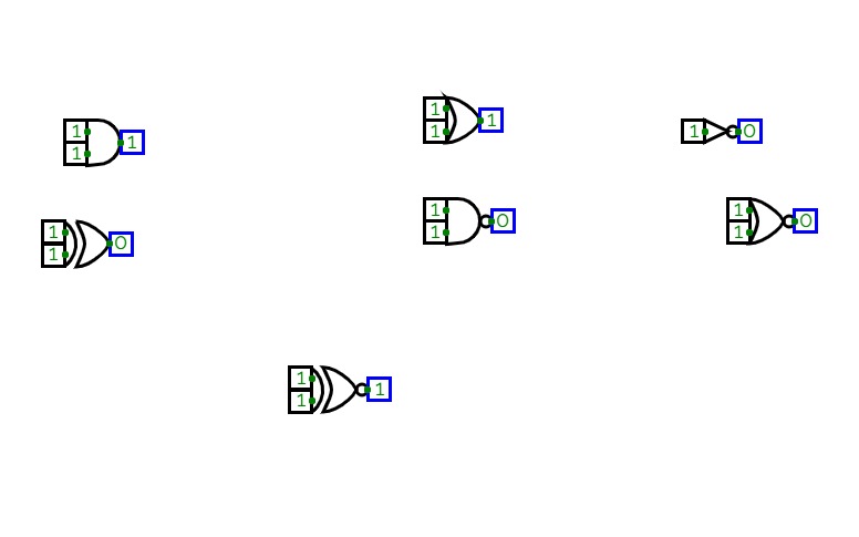
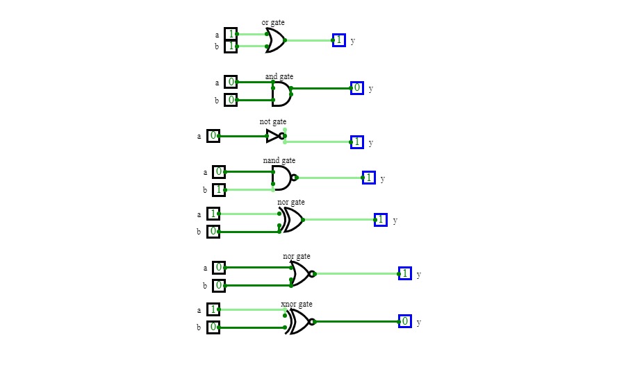
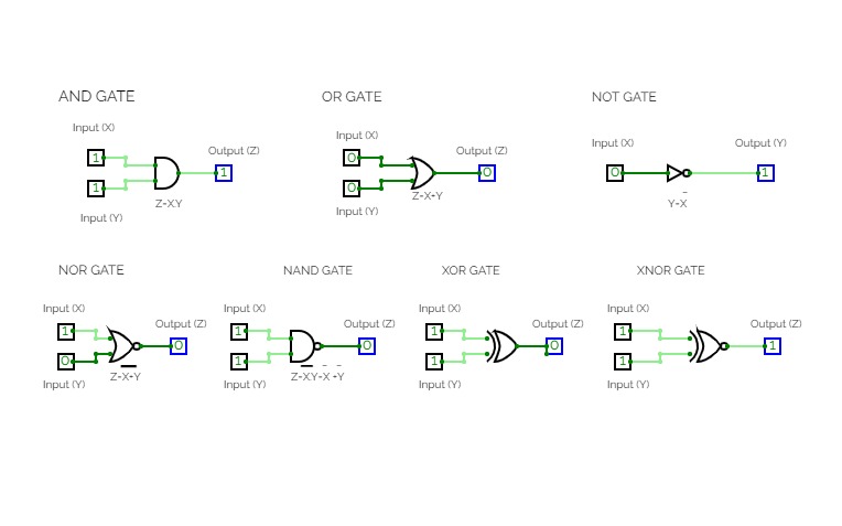
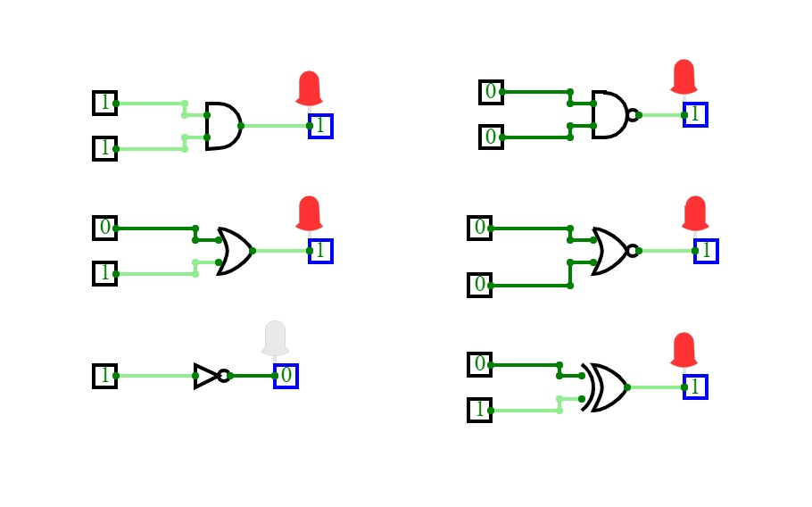
Basic Gates
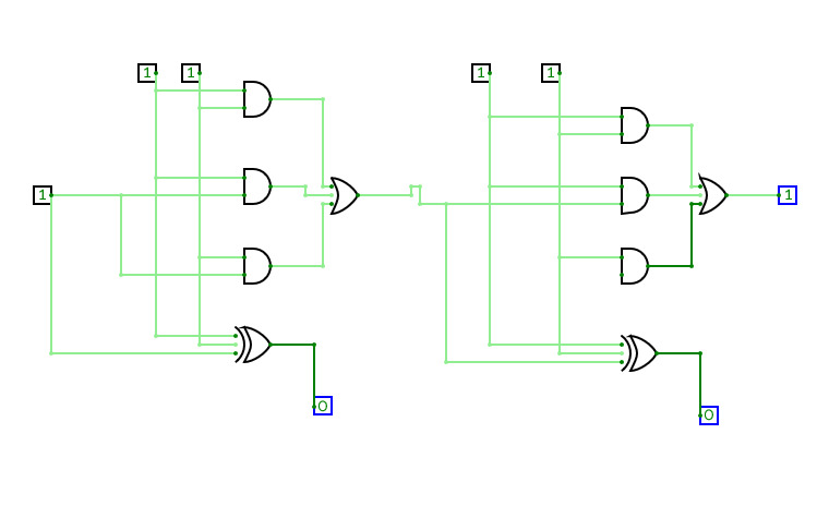
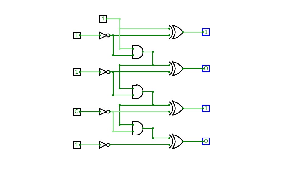
4 bits Left/Right Shiftcounter
4 bits Left/Right ShiftcounterOther than most designs this design uses the principal of a shift-register instead of a counter. I need less components.
Logic gates
Logic gates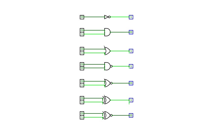
logic gates
logic gates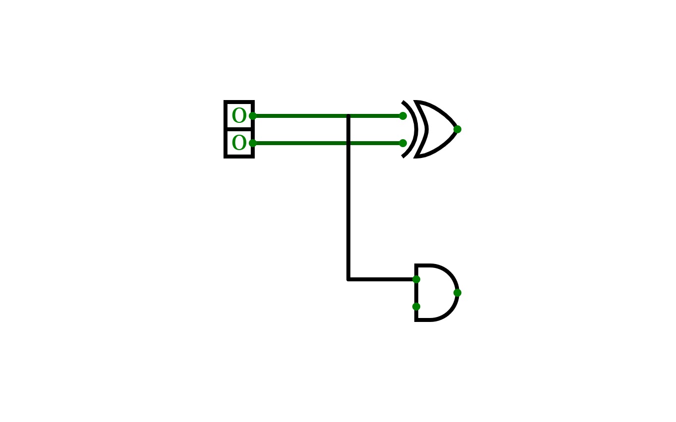
adders
adders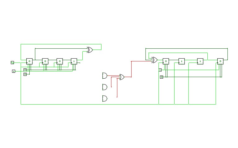
exaple1
exaple1example
5001_Aagash/Exercise-1 Verification of logic gates
5001_Aagash/Exercise-1 Verification of logic gates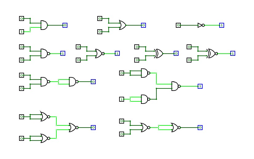
full adder using logic gates
full adder using logic gates
Half adder
Half adderThis circuit is regarding half adder.
Full adder using basic gates
Full adder using basic gatesfull adder,logic gates
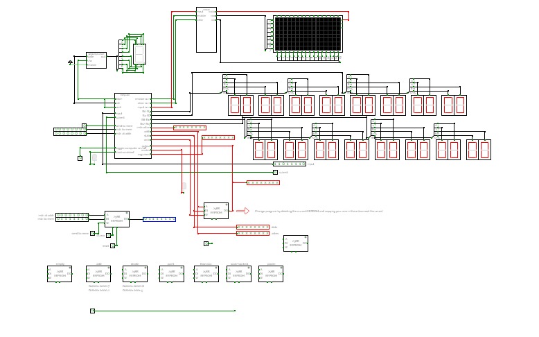
A computer made completely out of logic gates. Version 2. V1 can be found here: https://circuitverse.org/users/13948/projects/49969
Because of the limitations of the circuitverse.org simulator, and for easier use, some inbuilt components are used (like the 256-byte RAM module), but most of it is made up of OR, AND, NOT, XOR, NOR and NAND.
This project was originally made for my profile project. This is (or will be) version 2 of the 8-bit computer.
FULL ADDER
FULL ADDERThe complete adder can be realized using two semi-adders, the logic scheme is presented. Note that there is a common XOR circuit in the expressions: i and a ⊕b, so there may be this convenience
using to perform small cobra functions using an even smaller number of circuits.
Computational logic
Computational logic1 bit full adder circuit with numerical output display
logic gates(058)
logic gates(058)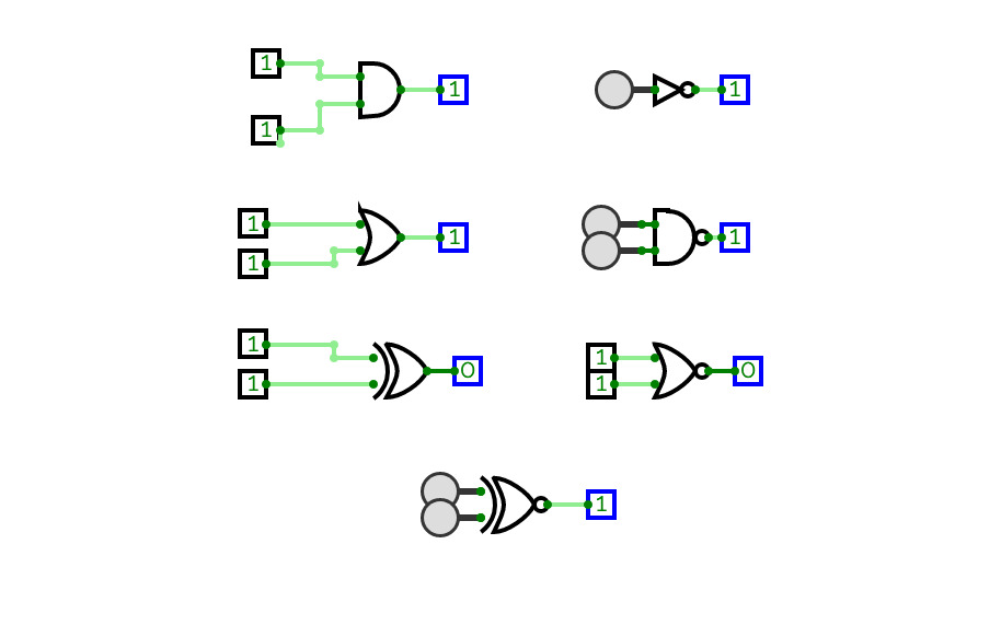
logic gates
logic gates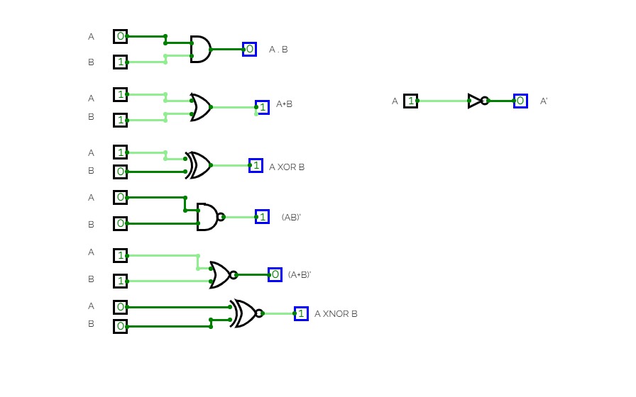
logic gates
logic gates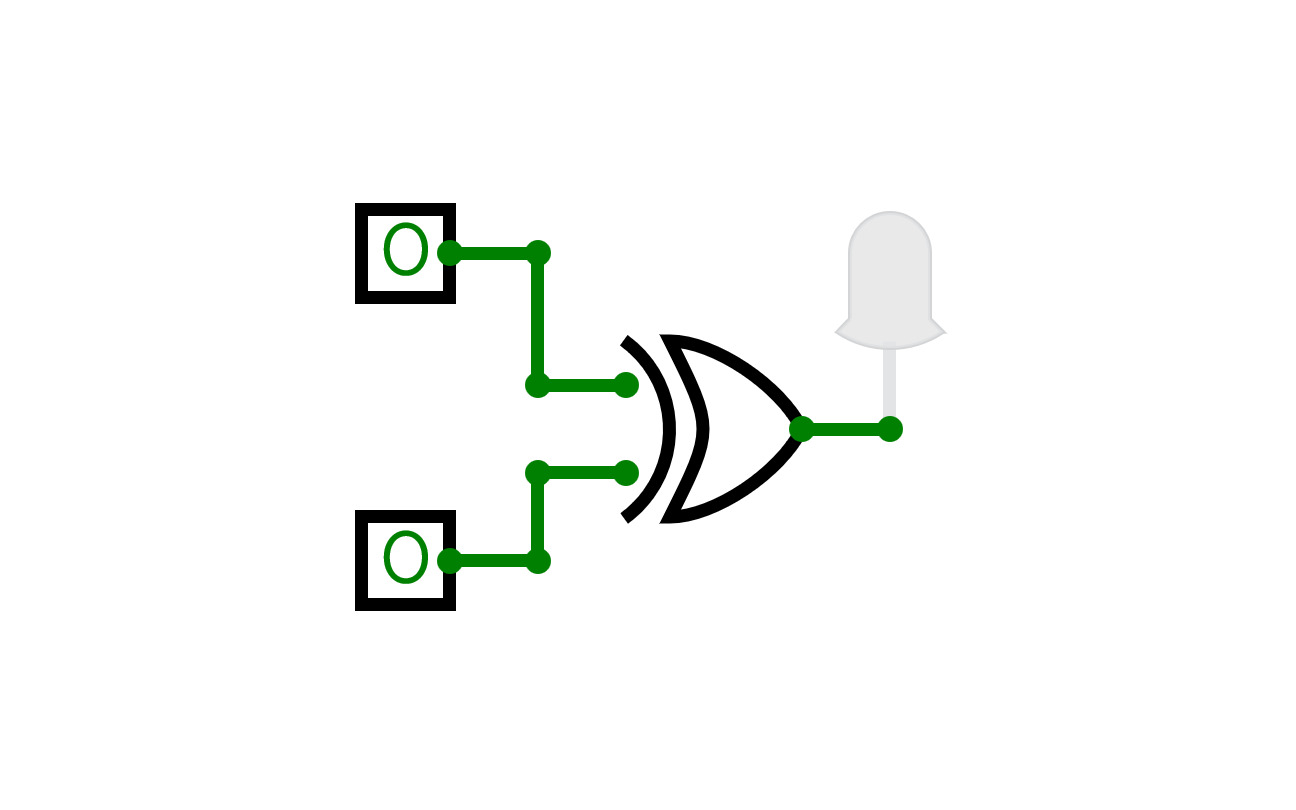
XOR
XORPuerta lógica XOR
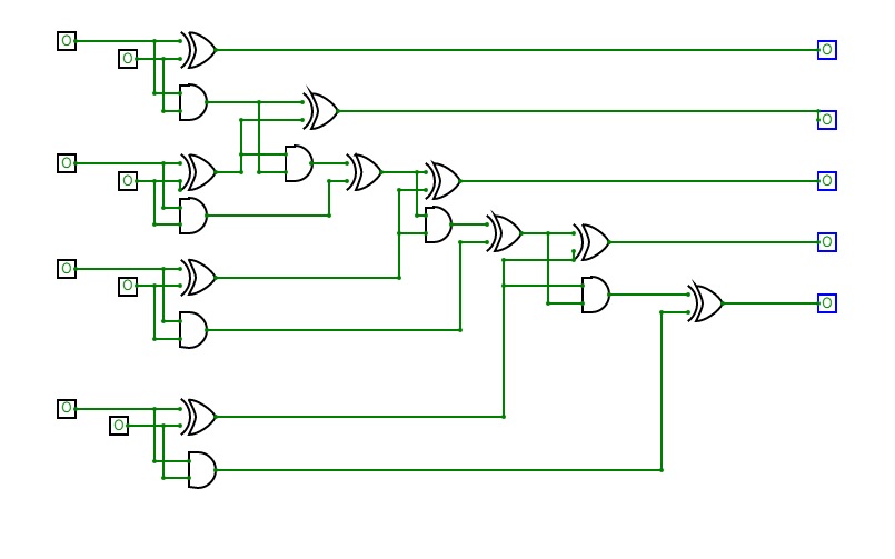
n bit ripple carry adder
n bit ripple carry adder
n bit triple order
n bit triple order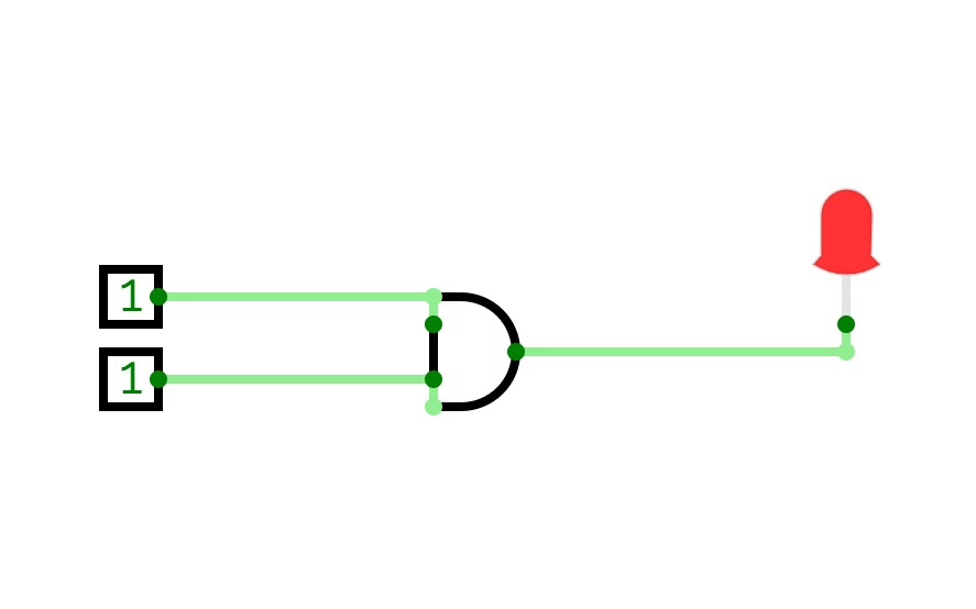
Basic
Basic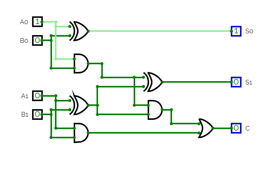
Sumador 2bit
Sumador 2bitPuerta mixta AND/XOR + puerta OR
expriment1:All logic gates
expriment1:All logic gates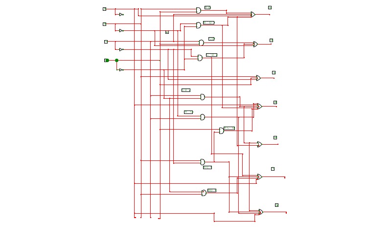

Assignment 2
Assignment 2my 2 nd assignment
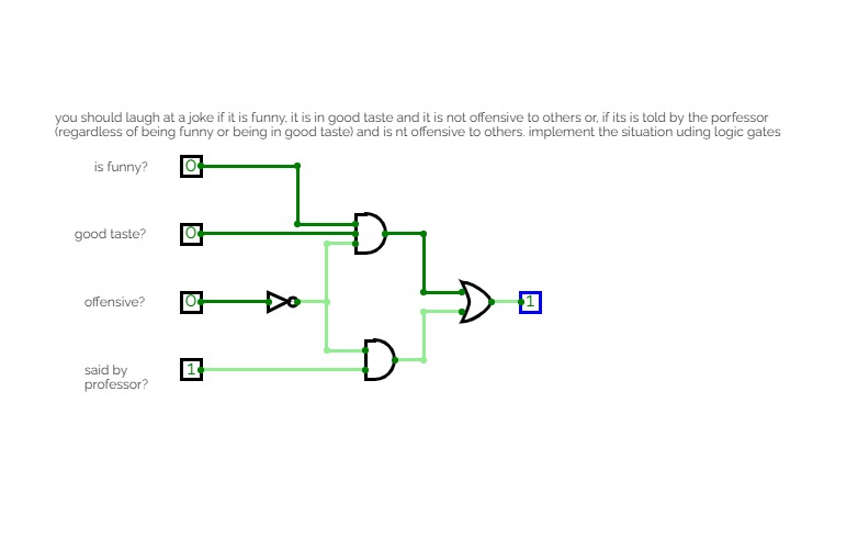

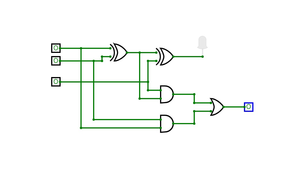
To laugh or not to laugh?
To laugh or not to laugh?you should laugh at a joke if it is funny, it is in good taste and it is not offensive to others or, if it is told by your professor (Regardless of it being funny or being in good taste) and it is not offensive to others. implement the situation using logic gates
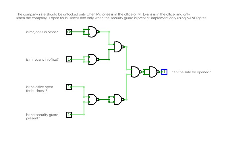
Excuse me? Who let you in?
Excuse me? Who let you in?The company safe should be unlocked only when Mr. jones is in the office or Mr. Evans is in the office, and only when the company is open for business and only when the security guard is present. implement only using NAND gates
PRASANTH S
PRASANTH S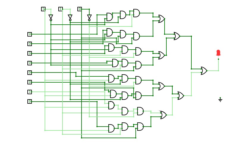

8x1 Multiplexer
8x1 Multiplexer8x1 multiplexer has 8 data input lines I0, I1, I2, I3, I4, I5, I6, I7, 3 select lines S0, S1, S2 and one output, Y.
Truth Table for 8x1 Multiplexer
Data Select Input
Output
Y
S2
S1
S0
0
0
0
I0
0
0
1
I1
0
1
0
I2
0
1
1
I3
1
0
0
I4
1
0
1
I5
1
1
0
I6
1
1
1
I7
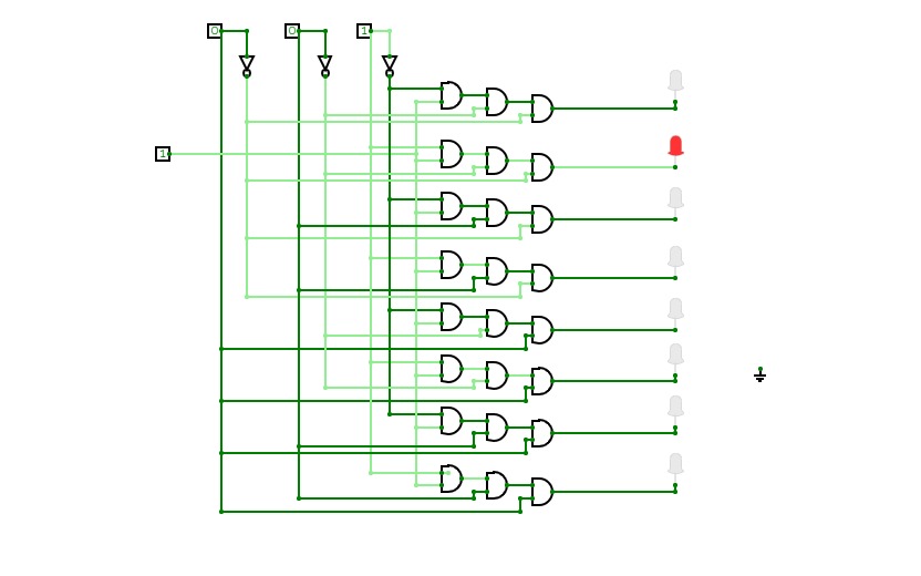
De Multiplexer
De Multiplexer1x8 de multiplexer has 1 input line I, 3 select lines S0,
S1, S2 and 8 outputs Y0, Y1, Y2,
Y3, Y4,Y5,
Y6, Y7
Truth Table of 1x8 DE MUX
Input
Data
S2
S1
S0
Y0
Y1
Y2
Y3
Y4
Y5
Y6
Y7
D
0
0
0
D
0
0
0
0
0
0
0
D
0
0
1
0
D
0
0
0
0
0
0
D
0
1
0
0
0
D
0
0
0
0
0
D
0
1
1
0
0
0
D
0
0
0
0
D
1
0
0
0
0
0
0
D
0
0
0
D
1
0
1
0
0
0
0
0
D
0
0
D
1
1
0
0
0
0
0
0
0
D
0
D
1
1
1
0
0
0
0
0
0
0
D
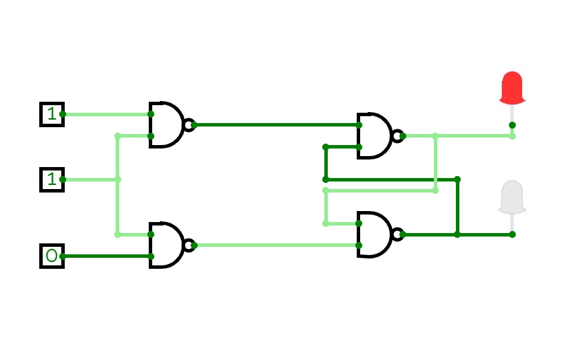
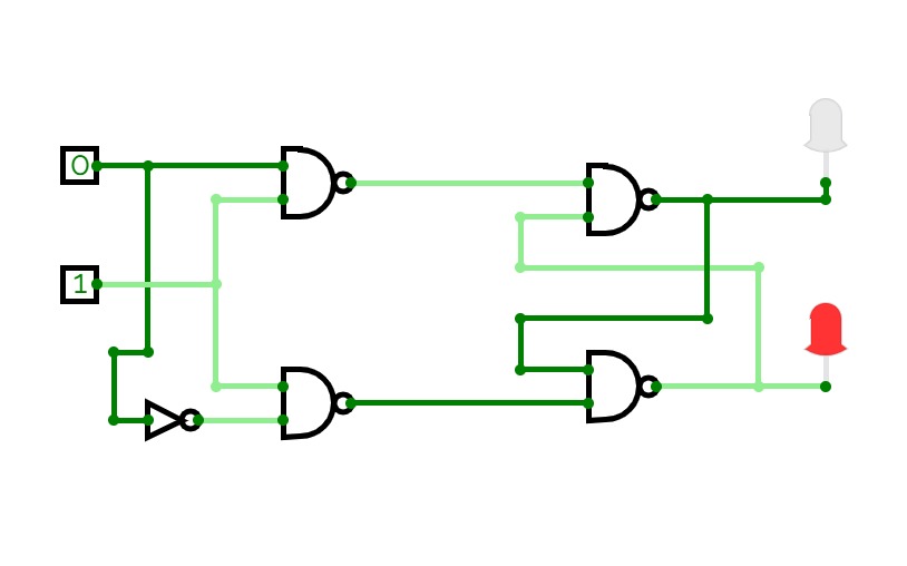
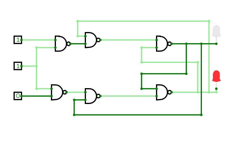
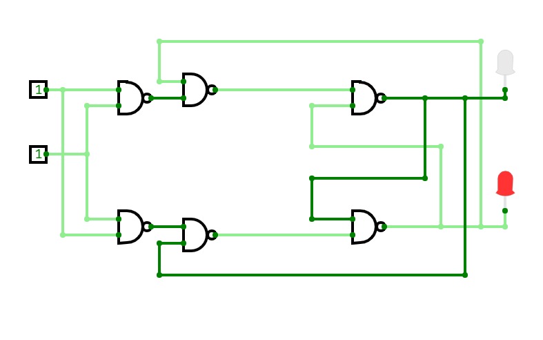
SR Flip Flop
SR Flip FlopThe basic NAND gate RS flip flop circuit is used to store the data and thus provides feedback from both of its outputs again back to its inputs. The RS flip flop actually has three inputs, SET, RESET and its current output Q relating to its current state.
Truth Table for RS flip –flop
Clk
R
S
Q
Q’
0
X
X
Previous or Memory State
1
1
0
0
1
1
0
1
1
0
1
0
0
Previous or Memory State
1
1
1
Invalid State
D flip-flop
D flip-flopA D flip flop has a single data input. This type of flip flop is obtained from the SR flip flop by connecting the R input through an inverter, and the S input is connected directly to data input. The modified clocked SR flip-flop is known as D-flip-flop and is shown below. From the truth table of SR flip-flop we see that the output of the SR flip-flop is in unpredictable state when the inputs are same and high. In many practical applications, these input conditions are not required. These input conditions can be avoided by making them complement of each other.
Truth Table for D flip-flop
Clk
D
Q
Q’
0
1
Previous or memory state
0
1
1
0
0
1
1
1
1
0
JK flip-flop
JK flip-flopIn a RS flip-flop the input R=S=1 leads to an indeterminate output. The RS flip-flop circuit may be re-joined if both inputs are 1 than also the outputs are complement of each other as shown in characteristics table below.
Truth Table for JK flip-flop
Input
Output
Clk
J
K
Q
Q’
0
X
X
Previous or Memory State
1
1
0
1
0
1
0
1
0
1
1
0
0
Previous or Memory State
1
1
1
Toggle State
T flip-flop
T flip-flopT flip-flop is known as toggle flip-flop. The T flip-flop is modification of the J-K flip-flop. Both the JK inputs of the JK flip – flop are held at logic 1 and the clock signal continuous to change as shown in table below.
Truth Table of T flip-flop
Clk
T
Q
Q’
0
1
Previous or memory state
0
0
1
0
1
1
Toggle state
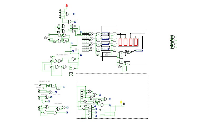
all in one rigisters ram stoage computer
all in one rigisters ram stoage computerthanks for checking out for any update contact me im also an ethical hacker and an os dev and an sr game engine dev so if you need any help check this list out
expt1
expt1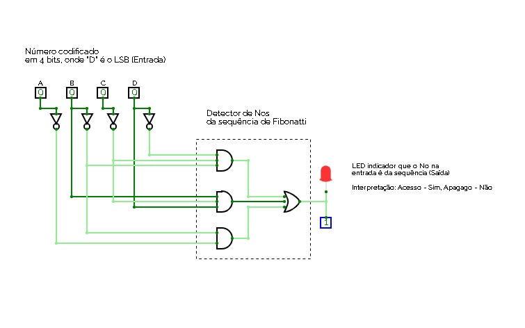
fibonatti number detector
fibonatti number detectorCircuit that detects if a number, encoded in binary (4 bits) belongs to the Fibonatti's sequence.
Circuito que detecta se um número codificado em 4 bits pertence a sequência de Fibonatti (in portuguese).
20BEI016 EX NO.1
20BEI016 EX NO.1LOGIC GATES
20BEI016_DE_EX NO.1
20BEI016_DE_EX NO.1LOGIC GATES
Contador 1-9
Contador 1-9Es un contador del 1-9
logic gates
logic gates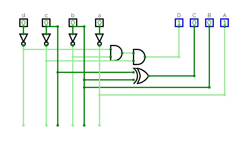
FCO - Practice 2
FCO - Practice 2Here is all of the 2º practice
END SEM LAB
END SEM LAB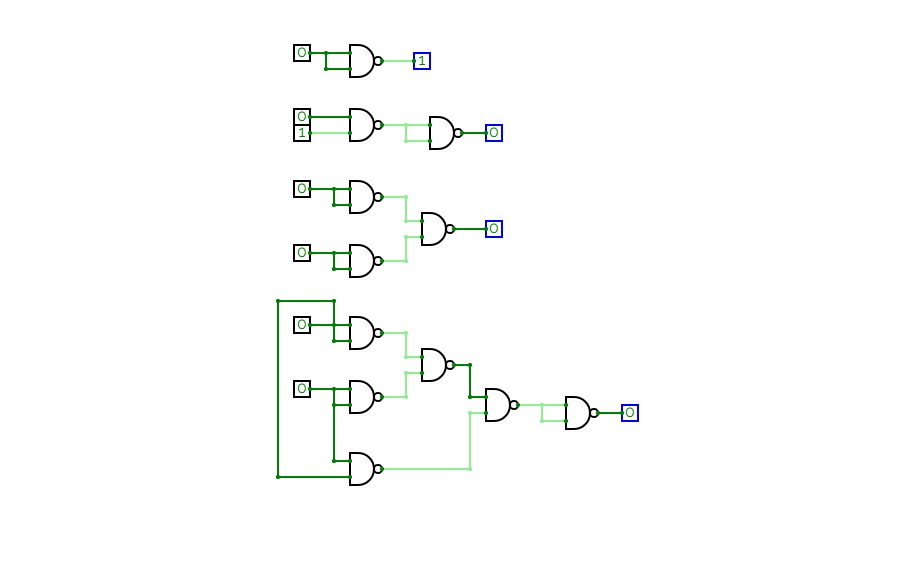
NAND blocks
NAND blocks
Gates
Gates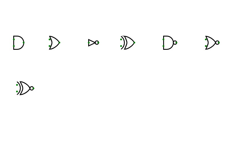
logic gates
logic gates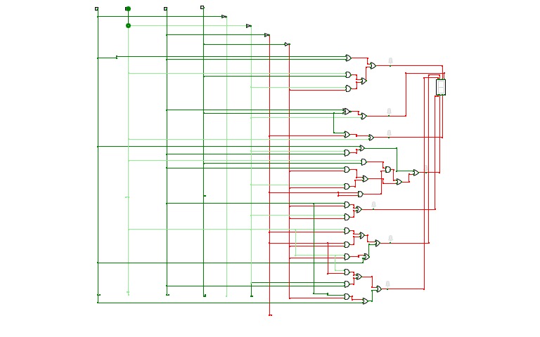
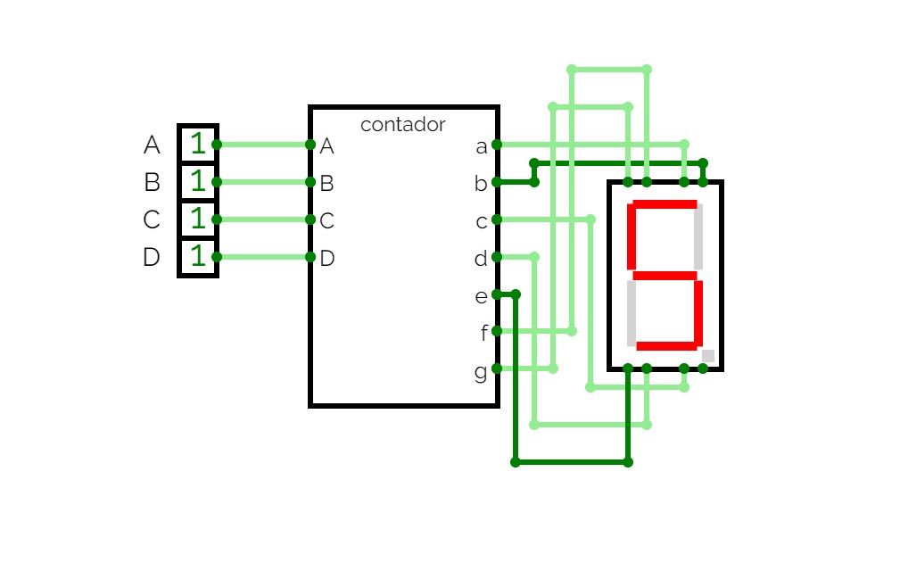
7 segment decoder
7 segment decoder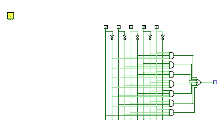
task
task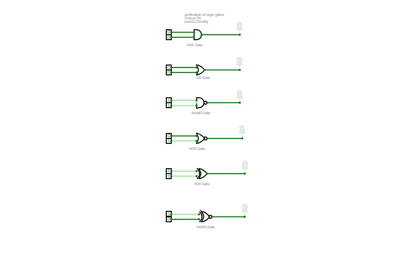
Verification of Logic gates
Verification of Logic gates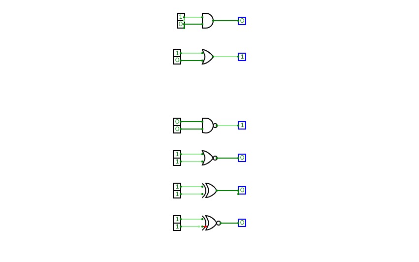
8 digit adder
8 digit adder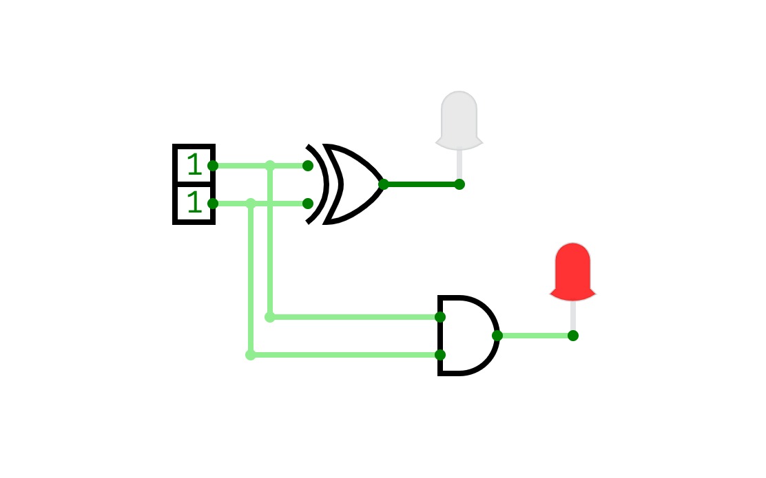
first logic
first logic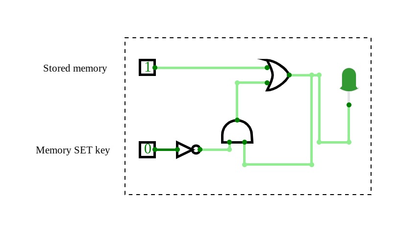
memory Latch
memory LatchThis is a memory latch that can reliably store one digit. When you store 1, the light is on. If you store 0, the light stays off. This may be confusing for some, but play around to see how you can store a digit.
( HINT: the set memory button will allow you to store a new number when it is on 1. When the set memory button is set as 0, you cannot make any modification to the stored memory. Use the ´stored memory´ button to toggle the digit you are storing)
circuit gates
circuit gates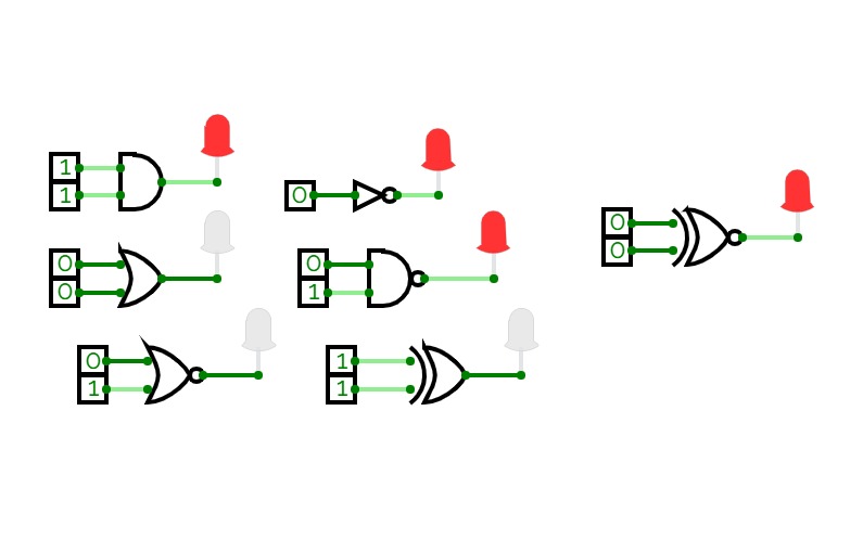
Dilip jadahv
Dilip jadahv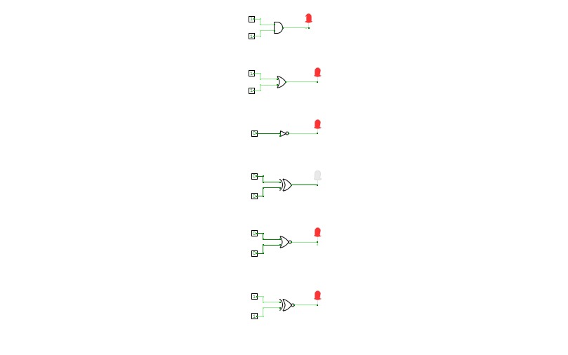
Experiment 1
Experiment 1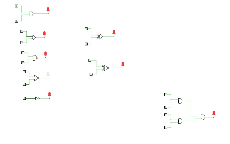
sayed rafat ali
sayed rafat ali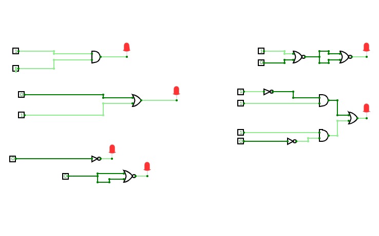
Untitled
UntitledThis is to undestand the various logic gates
Untitled
Untitled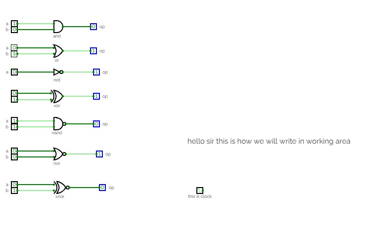
Untitled
Untitledtypes of logic gates
Experiment No 1
Experiment No 1
Ex1
Ex1logic gates Ex1
2's complement for 4 bit input
2's complement for 4 bit input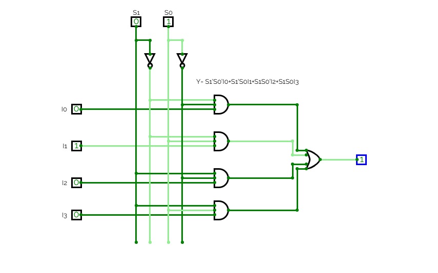
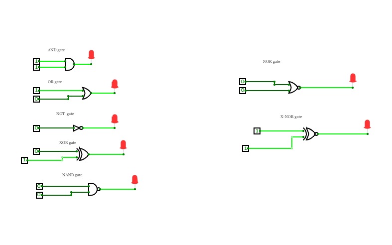
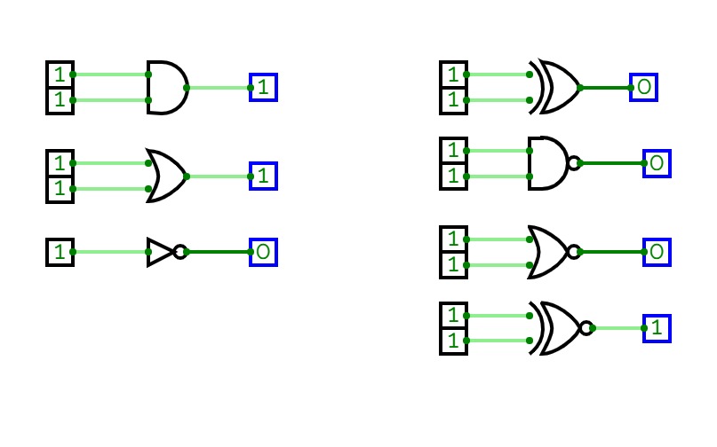
Digital Logic Assignment
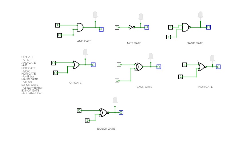
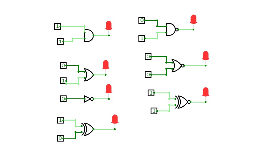
Digital Logic AssignmentA logic gate is a fundamental building block of digital circuits that performs a logical operation on one or more binary inputs and produces a single binary output. The output of a logic gate is determined by the combination of inputs applied to it. There are several types of logic gates, including AND, OR, NOT, NOR, NAND, XOR, and XNOR gates. These gates are used to execute various logical operations that are required by any digital circuit. Logic gates use Boolean algebra to perform logical processes. A truth table is a table that lists the outputs for all possible combinations of inputs that may be applied to a logic gate or circuit. Logic gates are found in nearly every digital gadget we use on a regular basis, including our telephones, laptops, tablets, and memory devices
I hope this helps!
basic gates
basic gates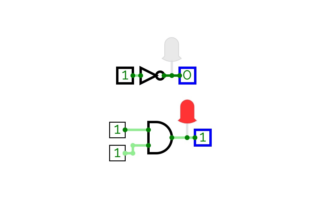
Level 1
Level 1
level 1
level 1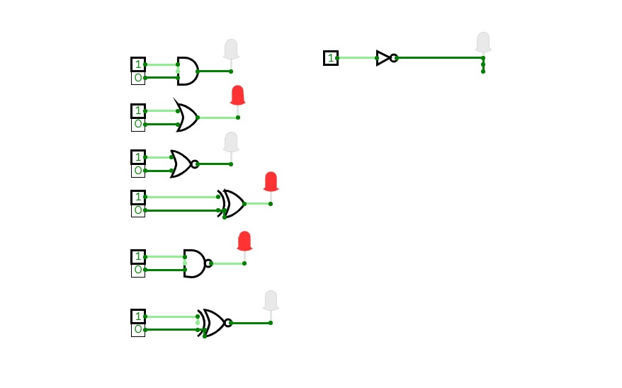
disha N
disha N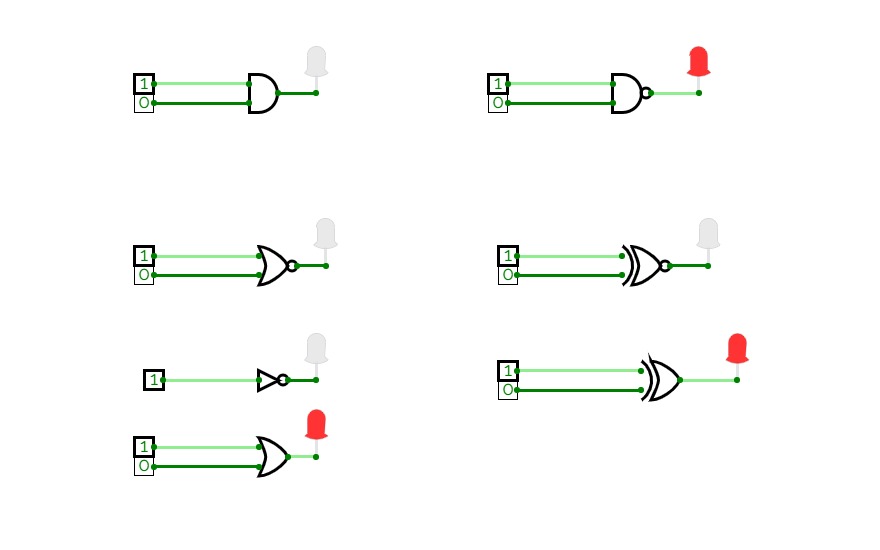
harshita ds
harshita ds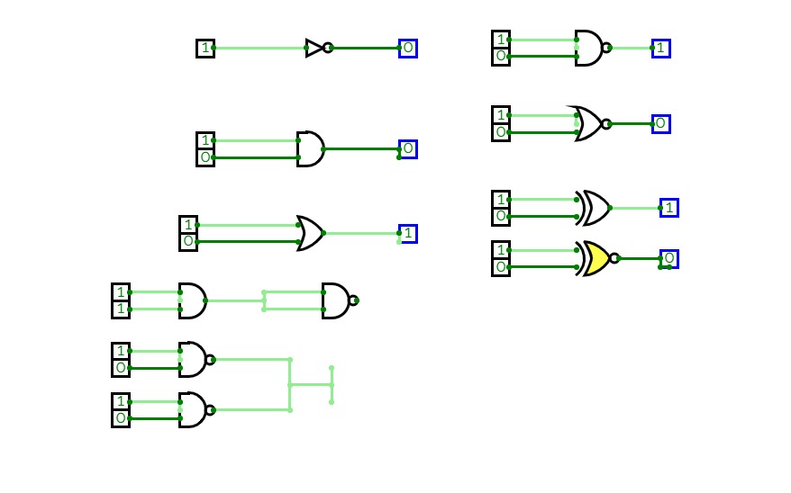
Devika P
Devika P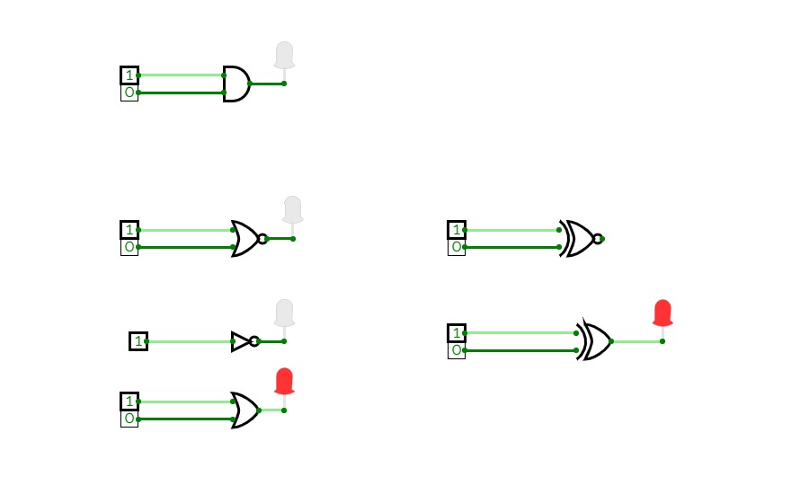
harshita ds
harshita ds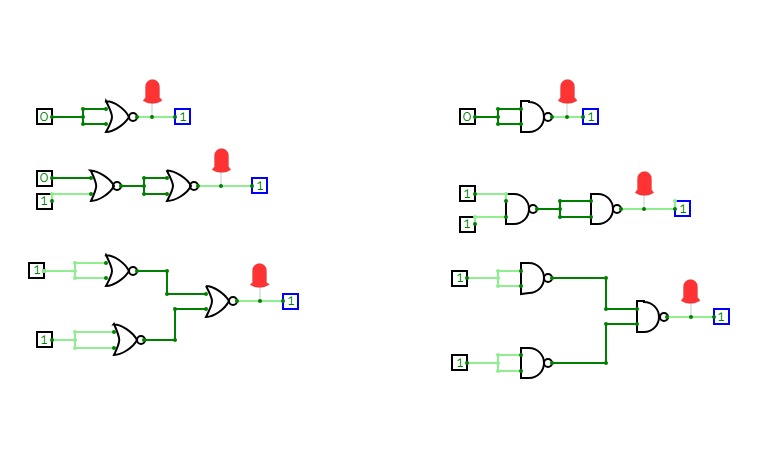
level 2
level 2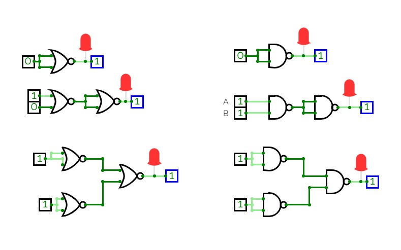
Level 2
Level 2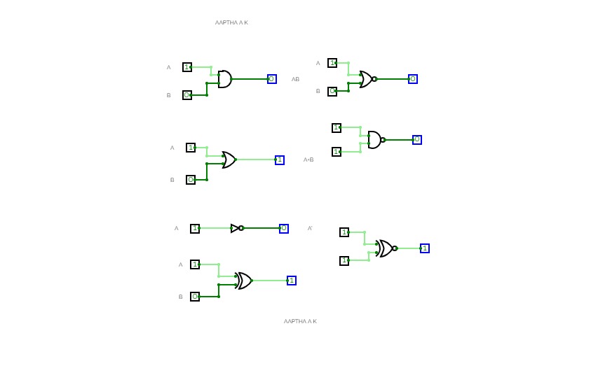
EXPERIMENT 1 LEVEL 1
EXPERIMENT 1 LEVEL 1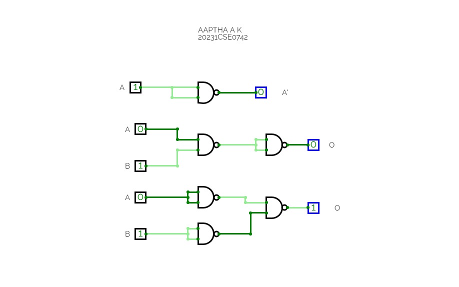
Untitled
Untitled
Experiment No 1
Experiment No 1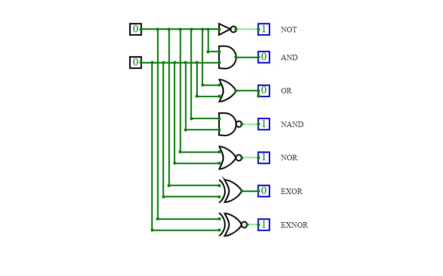
experiment 1 level 1
experiment 1 level 1
all gates
all gates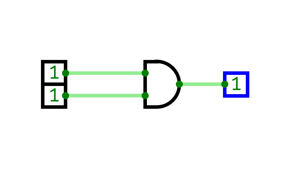
Sravanth Reddy
Sravanth Reddy
gates
gates
Untitled
Untitled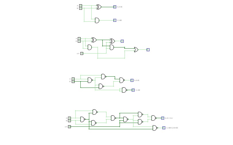
exp4.cv
exp4.cv...........

exp3.cv
exp3.cv...........

exp5.cv
exp5.cv.......

7 SEGMENT DISPLAY (EXP 8)
7 SEGMENT DISPLAY (EXP 8)7 SEGMENT DISPLAY
000 - q
001 - u
010 - I
011 - N
100 - 2
101 - 9
110 - 6
111 - 5

PRACTICAL TASK 1
PRACTICAL TASK 1to verify,
All the logic gates by designing the logic circuit with its truth table

logic gates
logic gates
exp 1
exp 1
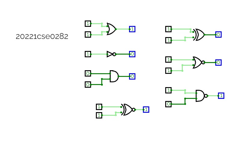
Truth tables
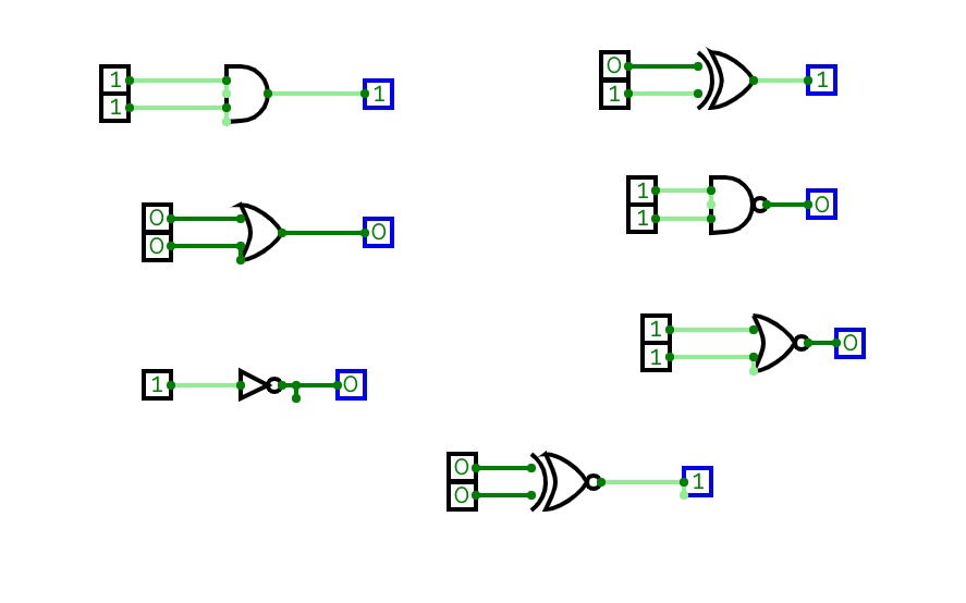
Truth tablesThe circuit consists of logic gates, universal gates, and extra gates along with their truth tables. The circuit provides input to the gates in the form of 0/1 and gives an output based on the gate.
The gates used are:
- AND
- OR
- NOT
- NAND
- NOR
- XOR
- XNOR

logic gates
logic gates
fazalnoor
fazalnoor
MADHUMITHA
MADHUMITHA
logic gates
logic gates
MSDHUMITHA
MSDHUMITHA
MADHUMITHA
MADHUMITHA
malavika level1
malavika level1
sanika project
sanika project
monisha project
monisha project
sanika.v project saved
sanika.v project saved
lab 1 logic gates
lab 1 logic gatesin this lab we discussed about the logic gates and their implementation and verification

kartiklogic
kartiklogiclogic gates and its verification and implementataion

sneha phy 08
sneha phy 08
Angelina Victoria
Angelina Victoria
k
k
first circuit
first circuit
Example Circuit problems
Example Circuit problemslogic gates

Implementation of Logic Gate
Implementation of Logic GateImplementation of Logic Gates

PRIYA_COA
PRIYA_COA
4 bit adder cum subtractor
4 bit adder cum subtractoraddition and subtraction operations using fixed numbers in 4-bit adder cum subtractor

exp-1
exp-1logic gates


