

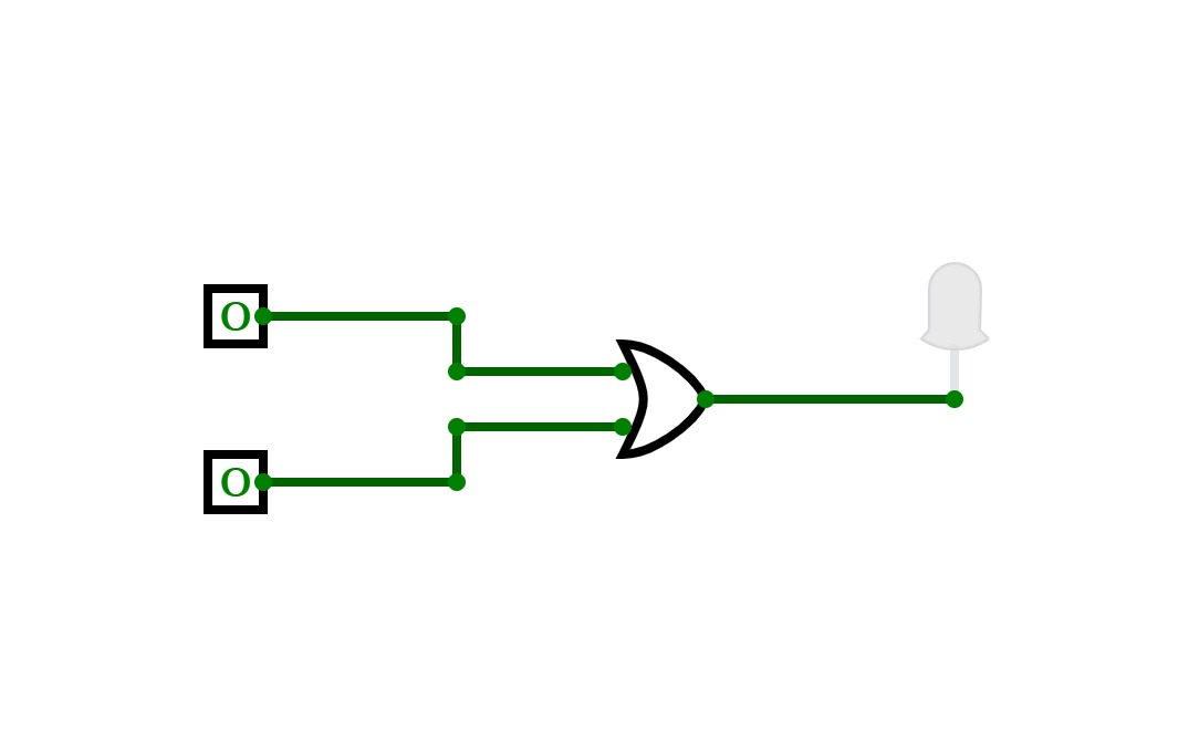
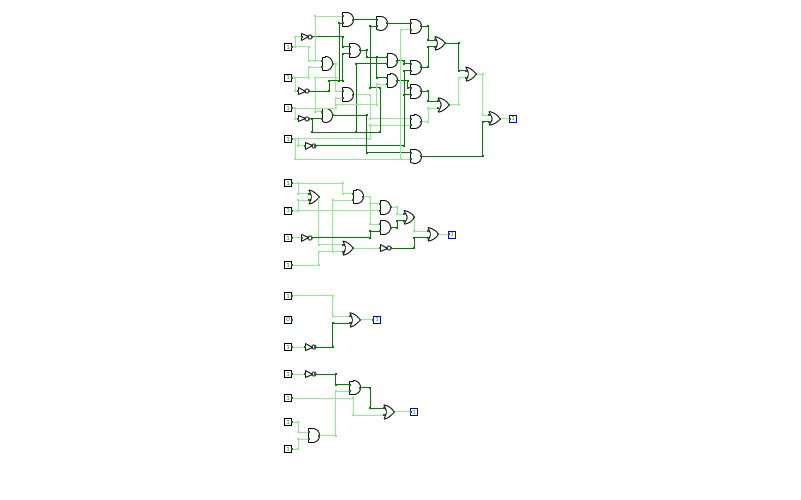
Sequential Logic
Sequential Logic
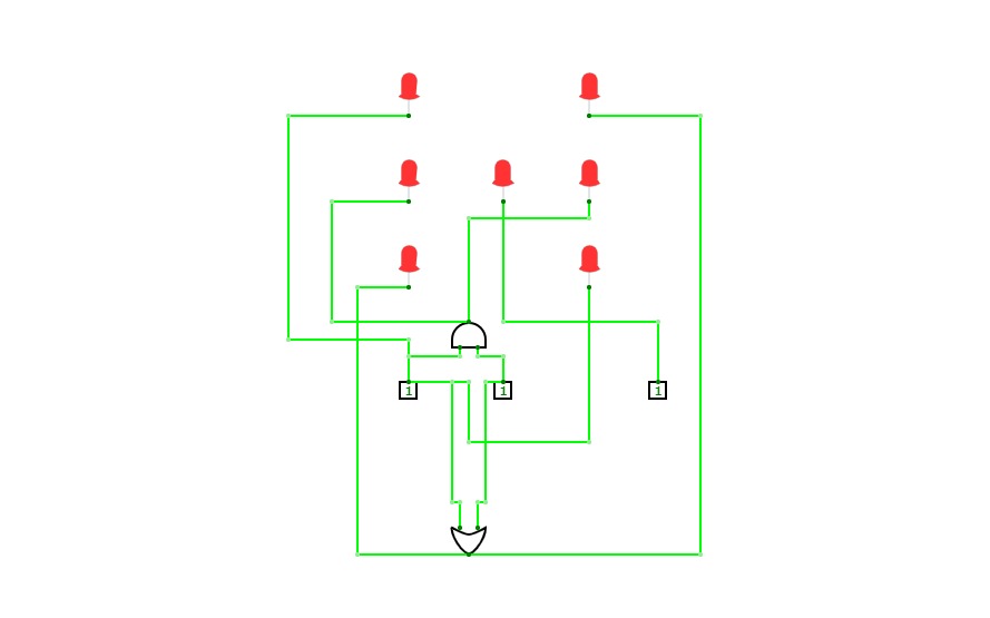
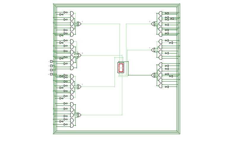
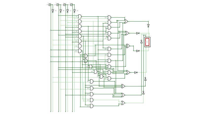
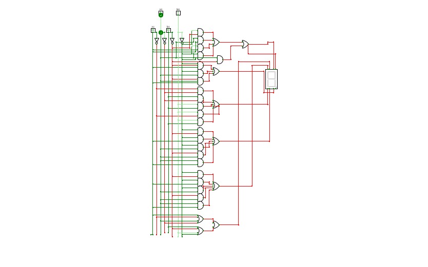
7 segment decoder
7 segment decoder4 BIT ALU
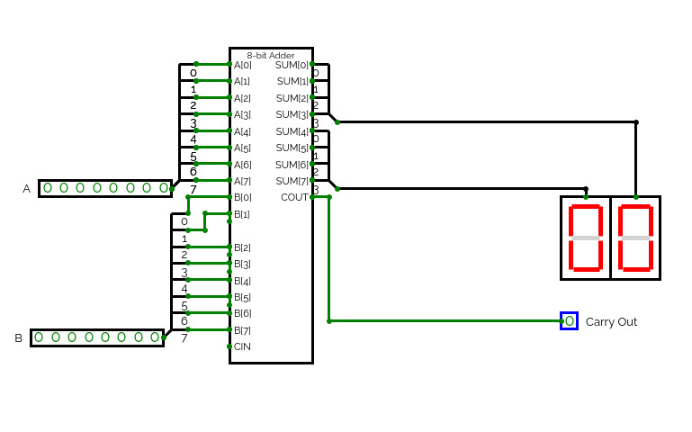
4 BIT ALUThis is part of a project to construct a 4 BIT CPU from scratch. I will be starting with a simple NOR gate and building it up to a working model with ALU registers, RAM and ROM. I will be designing an op code and assembler to go with it. Progress and detail can be found on my blog here
This file contains the ALU
This is a part of a project to construct a 4 BIT CPU from scratch. I will be starting with a simple NOR gate and building it up to a working model with ALU registers, RAM and ROM. I will be designing an op code and assembler to go with it. Progress and detail can be found on my blog here
This file cotains 4 bit versions of basic logic gates.
This is part of a project to construct a 4 BIT CPU from scratch. I will be starting with a simple NOR gate and building it up to a working model with ALU registers, RAM and ROM. I will be designing an op code and assembler to go with it. Progress and detail can be found on my blog here.
This file contains the basic logic gates.


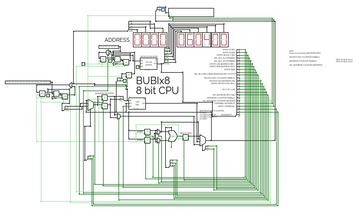
CombinationalLogic Lab
CombinationalLogic Lab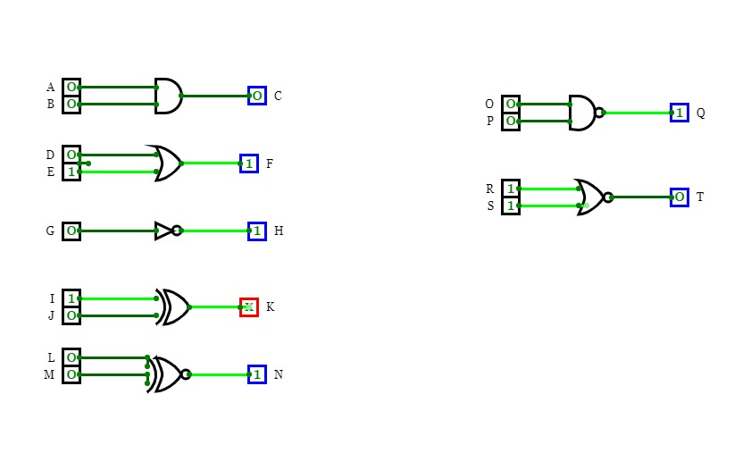
A computer made completely out of logic gates. Version 2. V1 can be found here: https://circuitverse.org/users/13948/projects/49969
Because of the limitations of the circuitverse.org simulator, and for easier use, some inbuilt components are used (like the 256-byte RAM module), but most of it is made up of OR, AND, NOT, XOR, NOR and NAND.
This project was originally made for my profile project. This is (or will be) version 2 of the 8-bit computer.
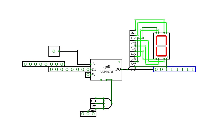
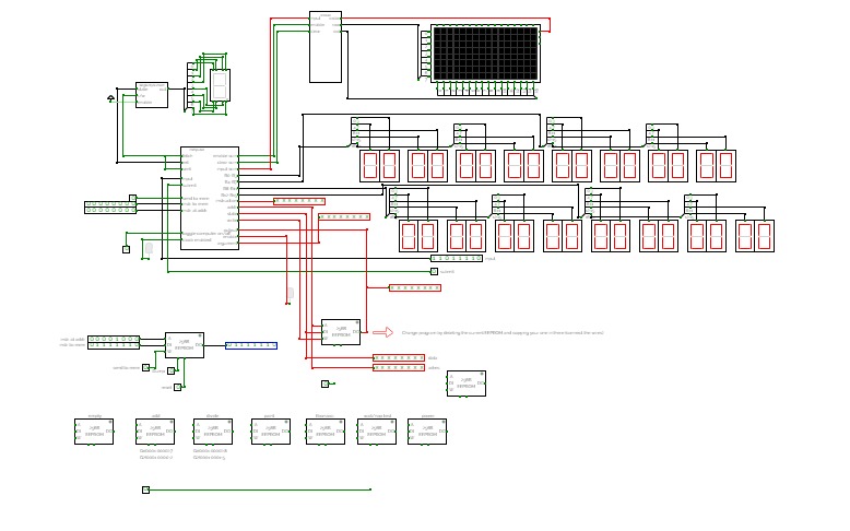
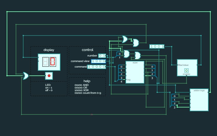
combinational logic with eeprom
combinational logic with eepromI'm using an EEPROM to replace combinational logic. The address is the decimal number in binary (or the counter). The data out is the 7-seg display (the leftmost bit is the decimal point).

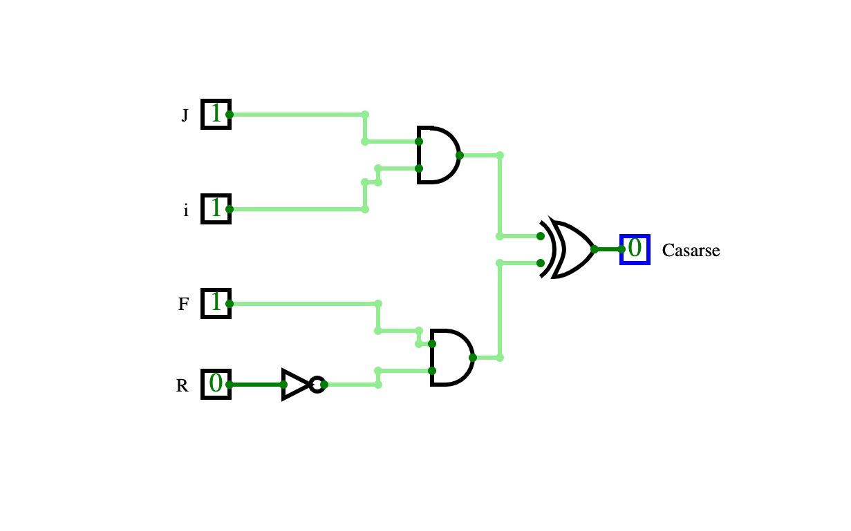
Decisión de casarse
Decisión de casarseEjemplo de razonamiento combinacional.
Me casaré con una persona joven e inteligente o que tenga fortuna y no ronque.
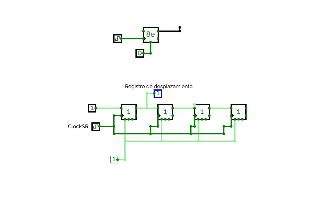
Shift Register
Shift RegisterFour bir Shift register
CSA_Lab2_Anwar
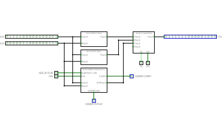
CSA_Lab2_AnwarComputer Systems Architecture
32-bit ALU, only with AND, OR, and ADDER/SUBTRACTOR.

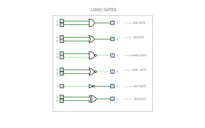
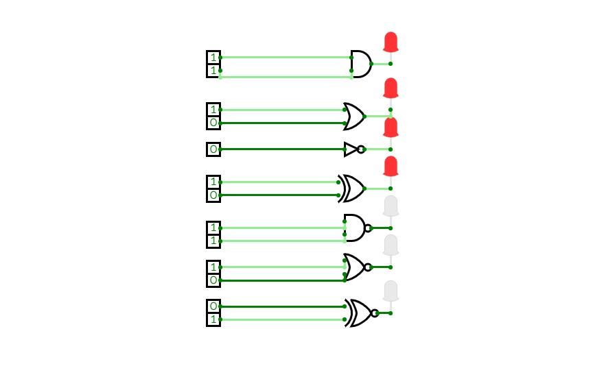

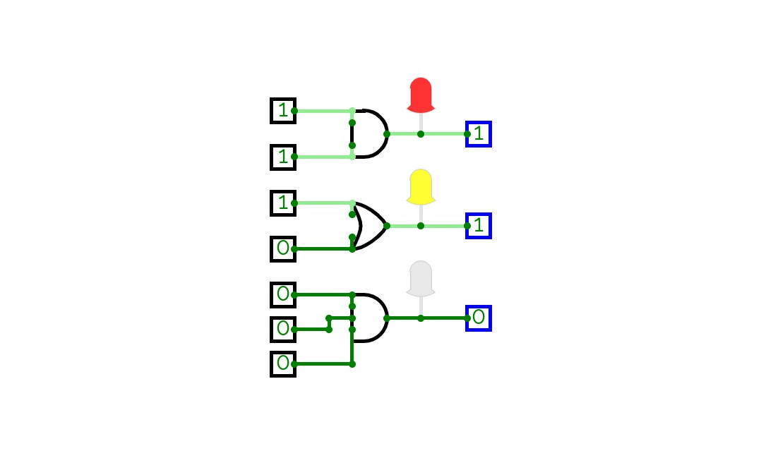
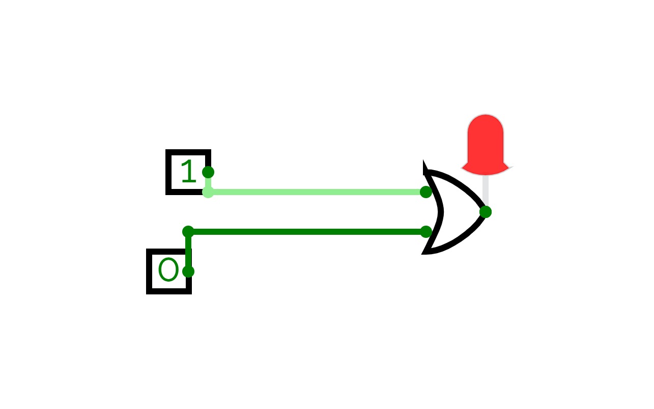
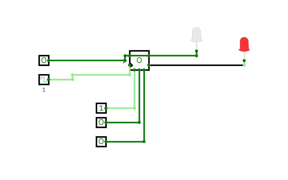
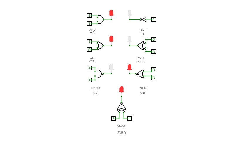
Logic Gates Verifcation
Logic Gates Verifcation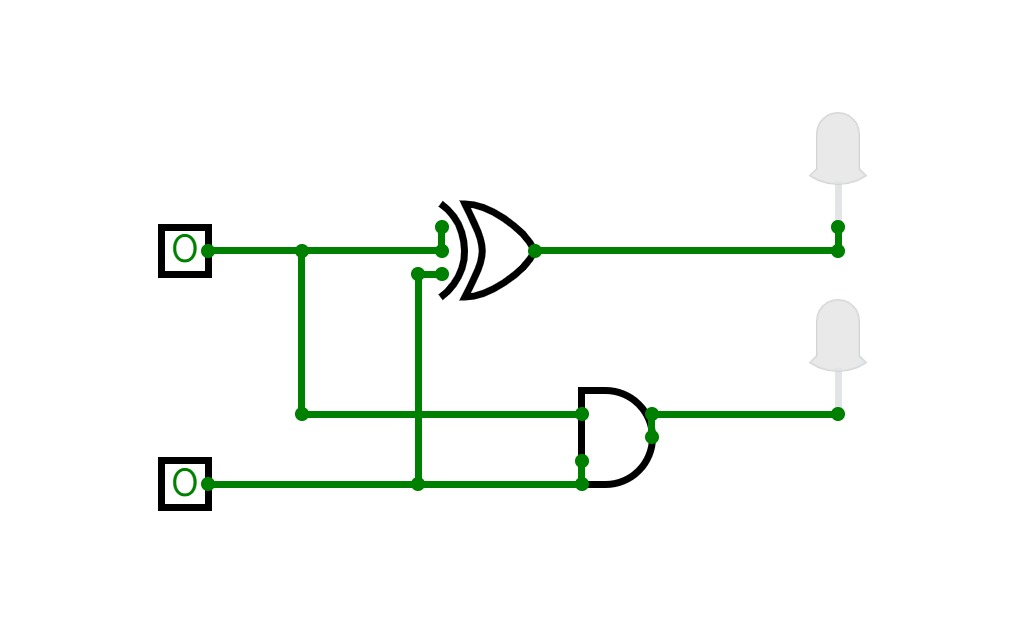
Half Adder
Half Adder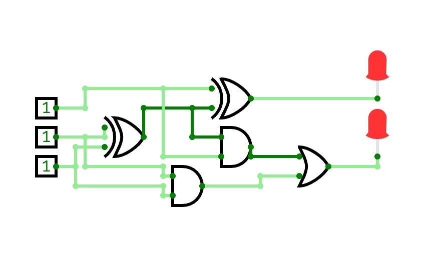
Full Adder
Full Adder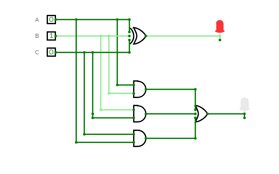
PROJECT 3 FULL ADDER
PROJECT 3 FULL ADDER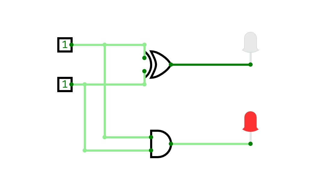
PROJECT 2 HALF ADDER
PROJECT 2 HALF ADDER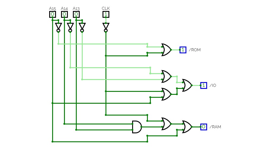
Clock
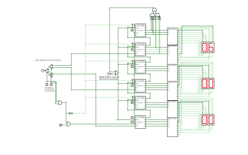
ClockThis is a simple digital clock with basic combinational and sequential logic circuits.
It can display seconds, minutes, and hours
Users can set time by clicking the button and using the multiplexer to choose which to change.
Also, the design for the 4bits 7segment display and 3 bits 7segment display is inside.
bintohex
bintohexThe circuit was made by a beginner to get some experience working with logic gates, k-maps and simulation software, there are many things that can be improved. Open for suggestions.
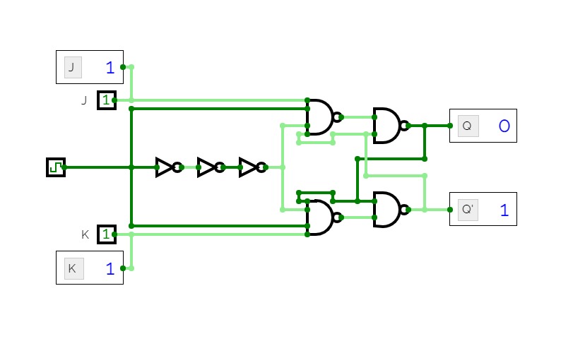
JK FlipFlop NAND Gates (Rising edge)
JK FlipFlop NAND Gates (Rising edge)This demonstrate the JK-Flipflop.
J 0, K 0 => do nothing
J 1, K 0 => Set (Q = 1, Q' = 0)
J 0, K 1 => Reset (Q = 0, Q' = 1)
J 1, K 1 => Toggle Q and Q'


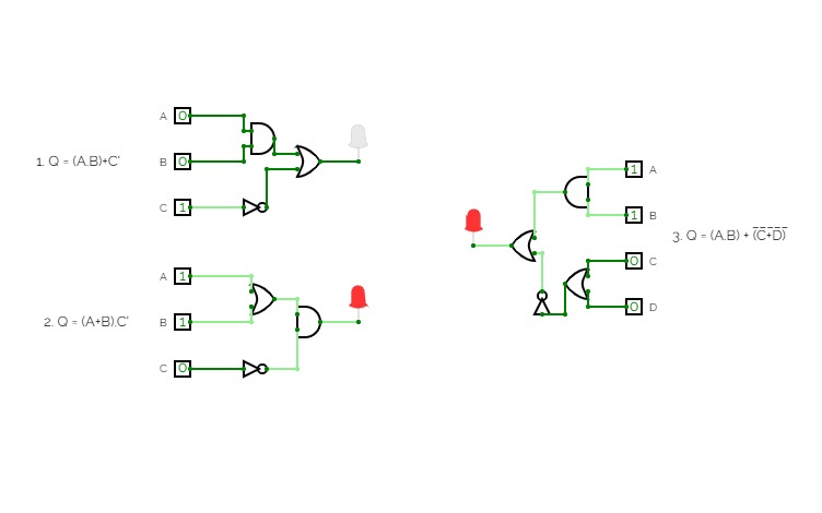
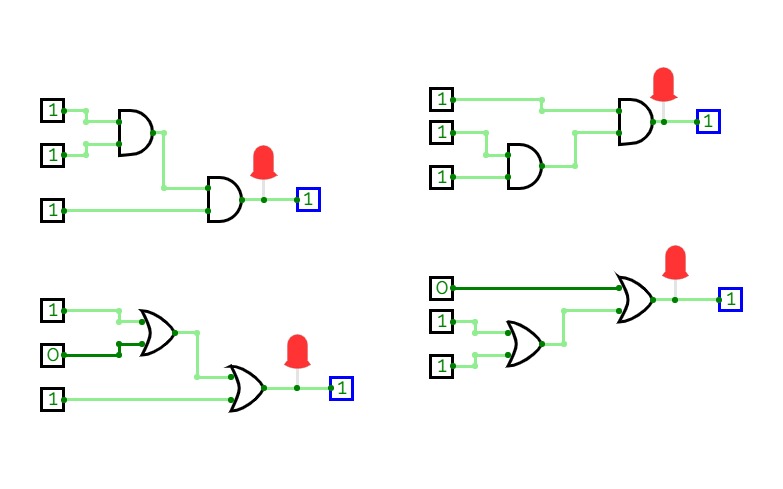
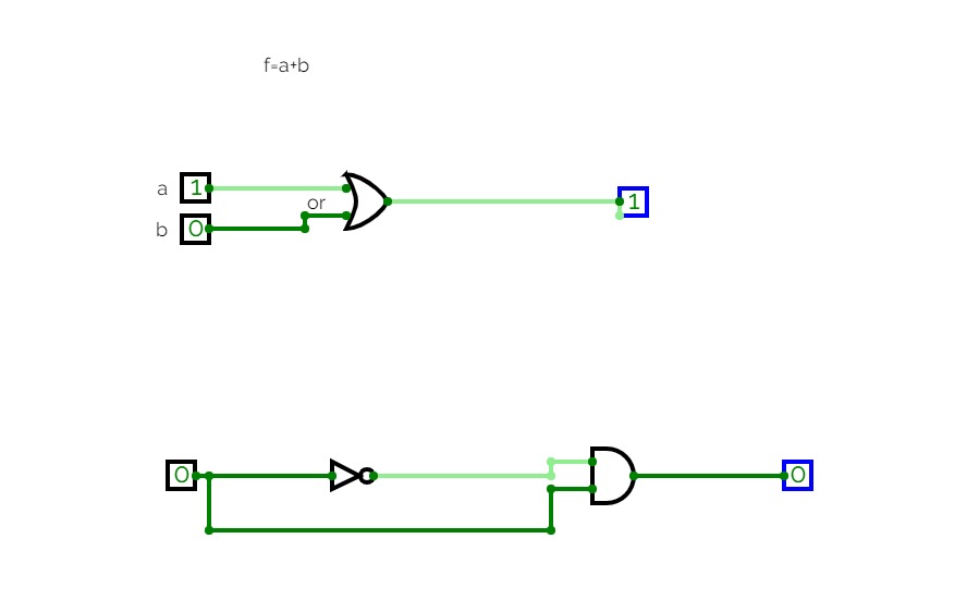
Associative Law
Associative Law
Experiment 2
Experiment 2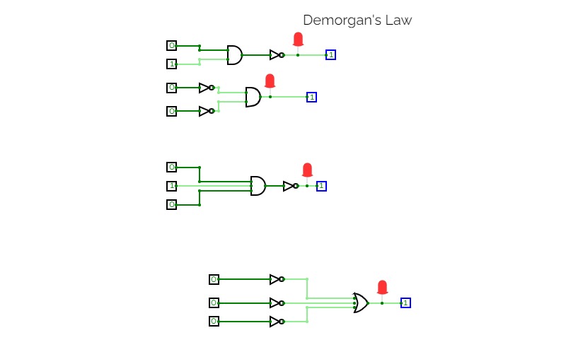
Demorgan's Law
Demorgan's Law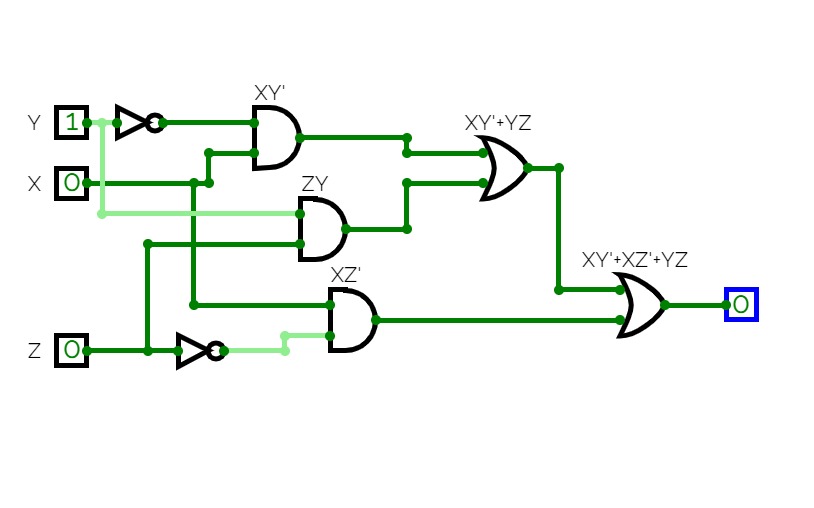

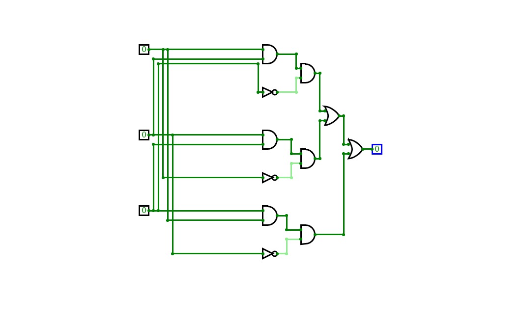
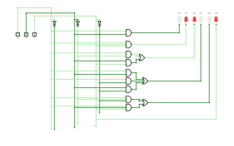
Draw the logic diagram for the function F(x, y, z)= xy’+xz’+yz
Draw the logic diagram for the function F(x, y, z)= xy’+xz’+yz
Exp 8
Exp 8

7 SEGMENT DISPLAY (EXP 8)
7 SEGMENT DISPLAY (EXP 8)7 SEGMENT DISPLAY
000 - q
001 - u
010 - I
011 - N
100 - 2
101 - 9
110 - 6
111 - 5


please read instructions before use
alu neutral instructions:
A IN/A OUT:0=take inputted a,1=save current output and use it as a until turned back to zero
B IN/B OUT:0=take inputted b,1=save current output and use it as b until turned back to zero
ALU SELECTION:0=take gate alu as output,1=take operation alu as output
DISPLAYS:
TOP 3=the systems current a
MIDDLE 3=output
BOTTOM 3=the systems current b
gate alu instructions:
GATE SELECTION:00=A AND B,01=A OR B,10=NOT A/B,11=A XOR B
A/B IN FOR NOT:0=take a as input for NOT,1=take b as input for NOT
operation alu instructions:
OPERATION SELECTION:0=A+B,1=A-B
SAVE A:put this alus current output in register a
SAVE B:put this alus current output in register b
OUT ALU:take output from alu
OUT A:take output from register a
OUT B:take output from register b

hello back logic world with a new project.
this time its multiplication but also contains multiple comparers
note:reset multiplications dont go away on thier own,this is the job of the reset button .another job for reset is turning on the machine when you only change a and yo can see why if you go to the curcuit


APCS 1
APCS 1
these notes are important please read them:
how to input code:
to input code please put your desired opcode into the computer on page "main", if you see that your codes are not being used properly, you are probably forgetting to turn on "ADD TO RAM" which enters your opcode into the program in the selected address, if you turn "ADD TO RAM" off later you can use the function saved at that address.
what the opcodes mean:
you probably don`t understand how my assembly works, but its actually really simple, the first 4 bits(from the left) are the functions, then the next are the first register address(unused in the manual input mode/function) then next is the second register(unused in not, input, full 1111 etc.) and the last 4 bits is where the output of the operation goes.
what the functions are:
1->not,2->and,3->or,4->xor,5->nand,6->nor,7->xnor,8->add,9->full 1111,10->left shift,11->right shift,12->input,13->copy,14->a if a>b,15->b if b>a and finally 16->sub
what the functions mean:
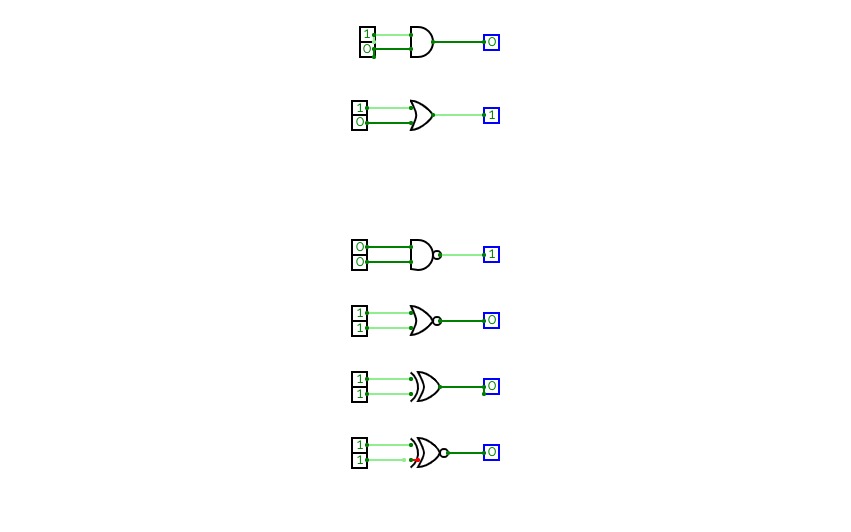
1. **NOT**:
- Inverts the input value (if a bit is 1, it becomes 0, and vice versa).
2. **AND**:
- Outputs 1 only if both inputs are 1. Otherwise, outputs 0.
3. **OR**:
- Outputs 1 if at least one input is 1. Outputs 0 only if both inputs are 0.
4. **XOR (Exclusive OR)**:
- Outputs 1 if the inputs are different (one is 1, the other is 0). Outputs 0 if they are the same.
5. **NAND**:
- Outputs 0 only if both inputs are 1. Otherwise, it outputs 1 (the opposite of AND).
6. **NOR**:
- Outputs 1 only if both inputs are 0. Otherwise, it outputs 0 (the opposite of OR).
7. **XNOR**:
- Outputs 1 if the inputs are the same (both 1 or both 0). Outputs 0 if they are different (the opposite of XOR).
8. **ADD**:
- Performs binary addition on the two inputs, outputting the sum,has no carry.
9. **FULL 1111**:
- makes the register`s value 1111.
10. **LEFT SHIFT**:
- Shifts all bits of the input to the left by one position, effectively multiplying the number by 2(discarding the most significant bit)
11. **RIGHT SHIFT**:
- Shifts all bits of the input to the right by one position, effectively dividing the number by 2 (discarding the least significant bit).
12. **INPUT**:
- Represents the initial data entering the circuit.
13. **COPY**:
- Takes an input from a register and puts it in another.
14. **A IF A > B**:
- Outputs the value of A if A is greater than B; otherwise, it outputs 0 .
15. **B IF B > A**:
- Outputs the value of B if B is greater than A; otherwise, it outputs 0.
16. **SUB**:
- Performs binary subtraction on the two inputs, outputting the difference and wrap if needed.


