2-Bit Counter (Up and Down)
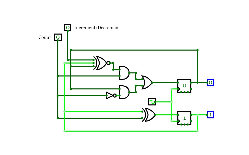
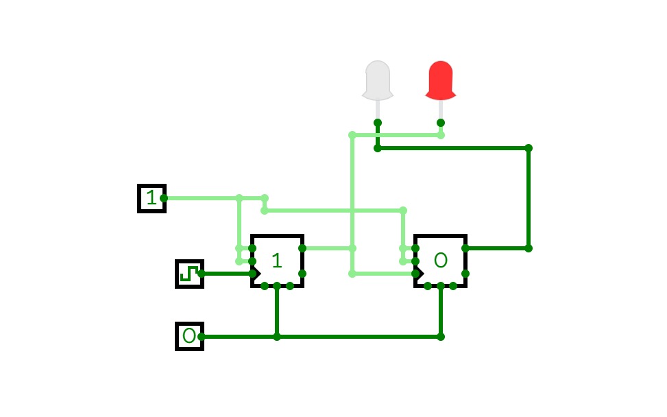
2-Bit Counter (Up and Down)A 2-bit counter that counts from 0 to 3! :D
Set "Count" to 1 to start counting and set it to 0 to pause the counter. Set "Increment/Decrement" to 1 to count up and 0 to count down.
Clock
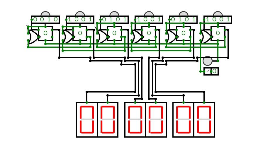
Clockthere are three different clocks that i have built in this showcase,
they all have some of the same principal rules;
the buttons above the 4 digit bit inputs are to move the face below it up by 1;
the button off to the side on the first and second are used to reset the clock if need be;
the input next to the box labeled 'P' is to turn it on or off
they all have slightly different quirks though
the first one is the very first prototype of a digital clock that i have made
the second is a smaller design that i shoved the wires from the previous into their own bok to make it look nicer; this was the first legitimate one though.
the third and final clock is what i dub the mini clock because it is my smallest clock that i have ever made; i essentially made some tweaks to the wiring and then put that on to its own very small circuit, the mini has a toggleable reset and power
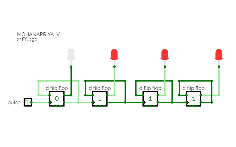
Counter
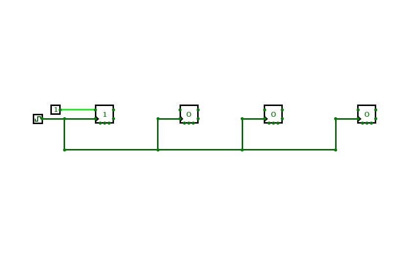
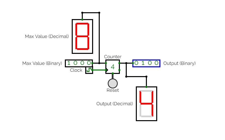
CounterA completely original (4-bit) counter I made.
simple computer
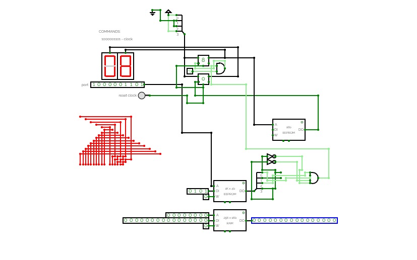
simple computersimple computer with clock
commands:
10001: Clock
00011: Do a OR operation*
01101: Do a AND operation*
01110: Do a NAND operation*
01001: RAM edit/read**
*Use number inputs too do the logic.
**Use data inputs edit/assign values to an 8-bit RAM. Use the R/W pin to read & write.
Specs:
RAM:
1KB (as seen in photo)

Clock:
2HZ (as seen in photo)

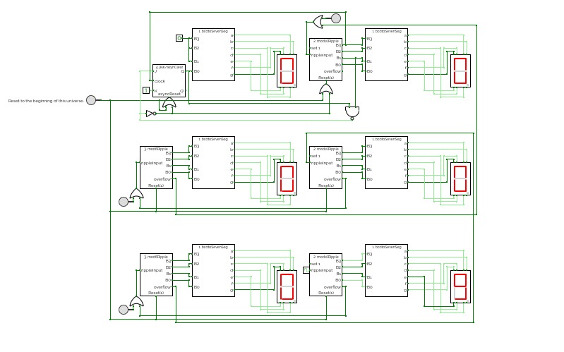
12hr digiClock
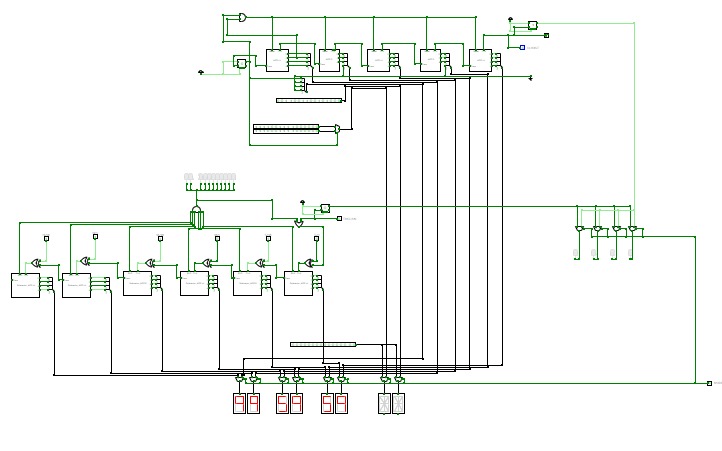
12hr digiClockThere's several buttons in the circuit. If you figure out what those do, the laws of time of this circuit's universe are yours to behold.
Note to future me to fix the following bug (if it even exists in the real world due to propagation delay).
The set 1 function of #2 works in the sub-circuit but fails to work for the output pulse in the main circuit. This is troubling to say the least. So I've decided to change hour 12:00 to 00:00.
d-flipflop
d-flipflopClock
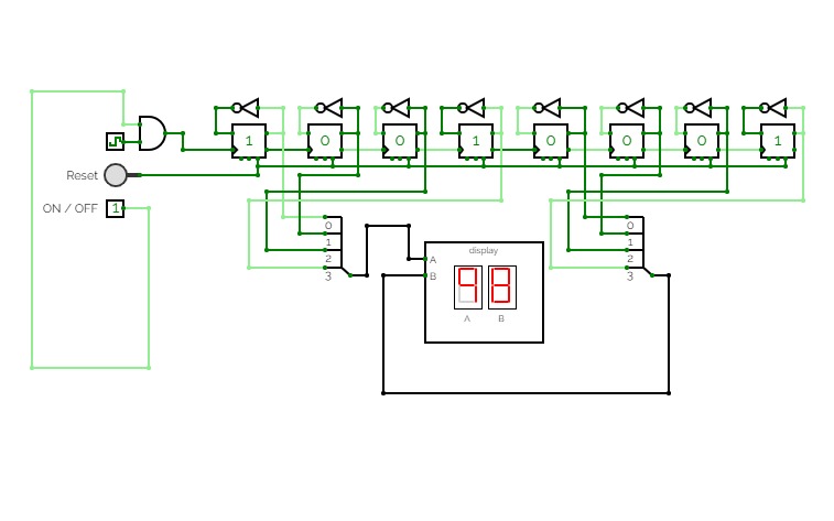
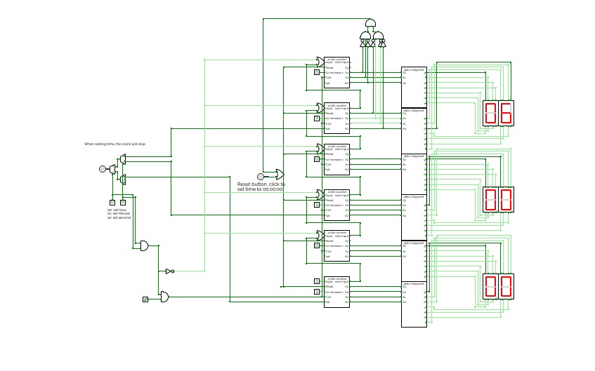
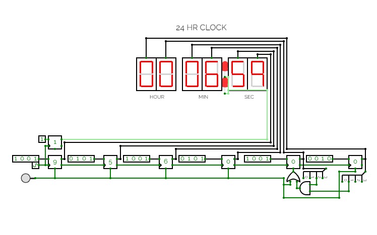
ClockThis is a simple digital clock with basic combinational and sequential logic circuits.
It can display seconds, minutes, and hours
Users can set time by clicking the button and using the multiplexer to choose which to change.
Also, the design for the 4bits 7segment display and 3 bits 7segment display is inside.
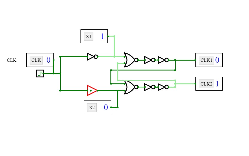
licznik asynchroniczny
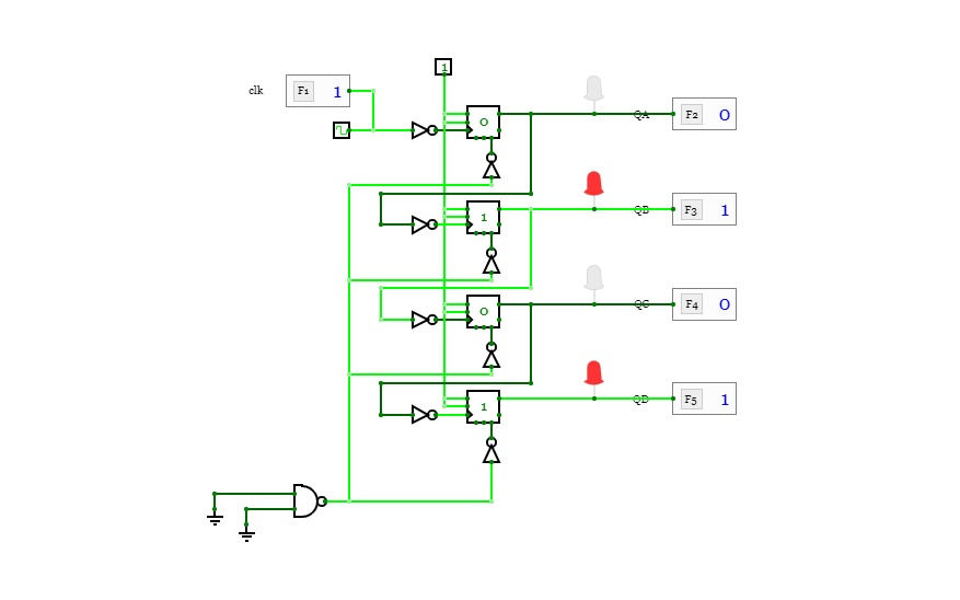
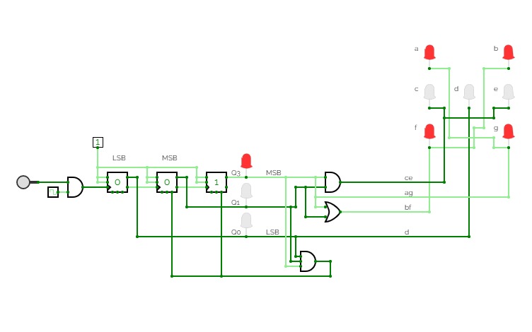
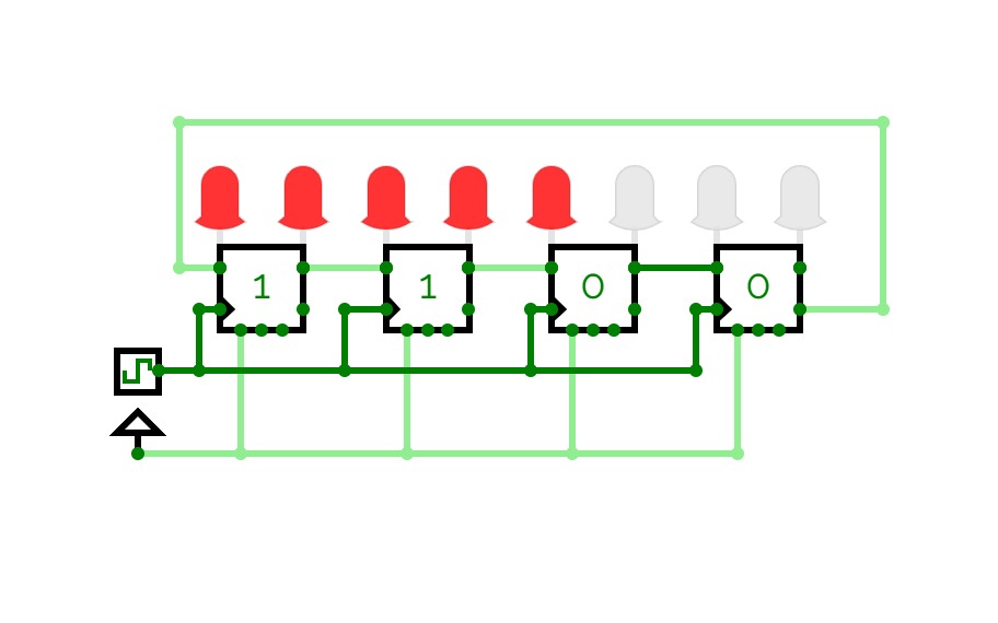
licznik asynchronicznyLicznik asynchroniczny modulo 4 liczący od tyłu (11 -> 10 -> 01 -> 00) wykonany na przerzutnikach typu jk
Four‐bit binary counter with parallel load
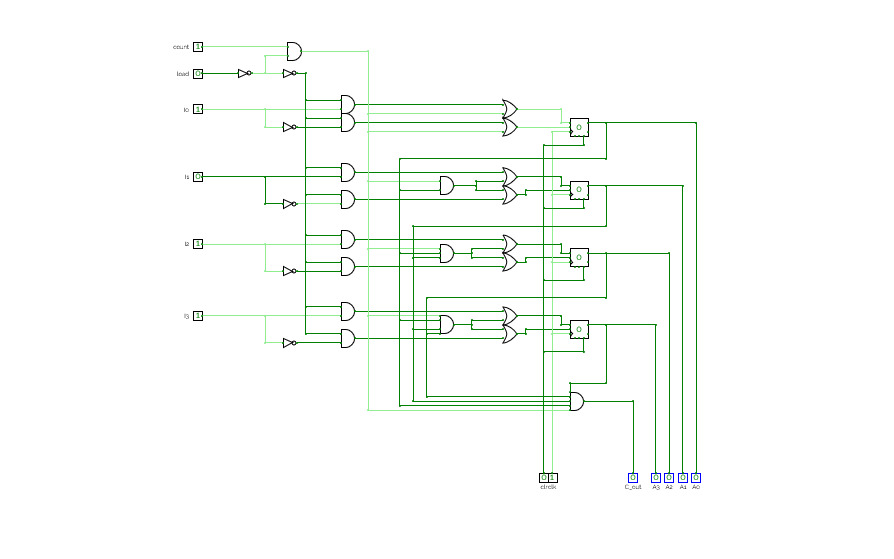
Four‐bit binary counter with parallel loadFour‐bit binary counter with parallel load. Do check it out. It has been tested!
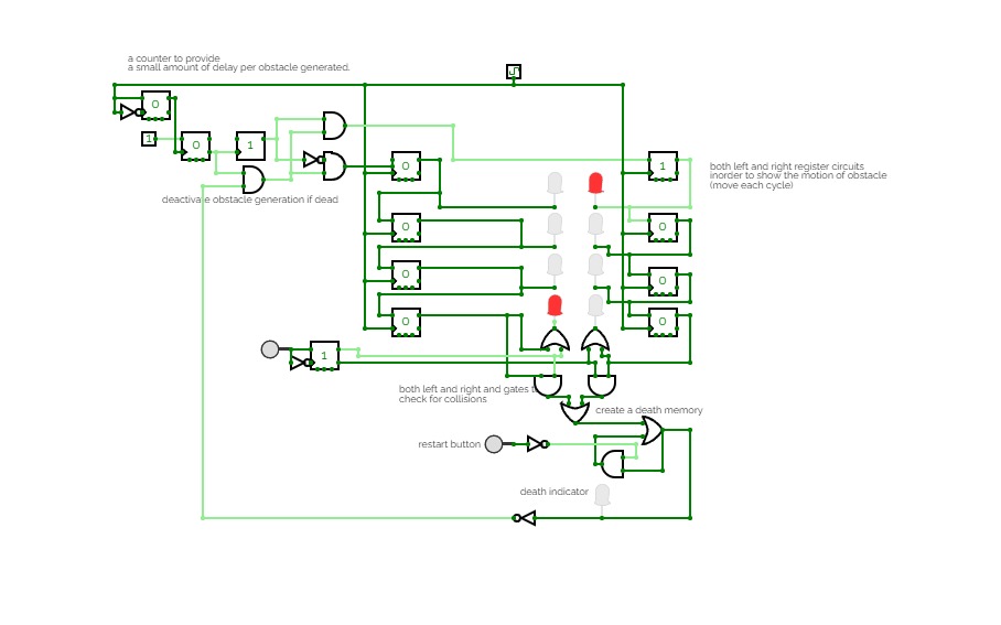
Use the button inorder to jump from left to right and vice vera and try avoiding the incoming obstacles.
If you collide with it you die and can restart using the restart button given at the bottom.
Change the difficulty by reducing the timing setting of the clock and good luck :D.
rixis combinox r1 cpu computer
rixis combinox r1 cpu computerAbout the Combinox R1:
This is the third 16-bit CPU I have made. Its new name was inspired by the new combinational code. It is also my first computer to feature a graphics and base ten display. As a result of its brand new architecture, code, and clock it is much faster than my previous CPUs.
Directions for use:
Choose the desired EEPROM program and insert it into the slot. First press the "RESET" button. Now press the "ON" button and enjoy your program.
Descriptions of programs:
blank: A blank EEPROM to be coded.
count up forever: Counts up by one until it reaches 65,535 then loops back to 0.
2+2: adds 2+2 and displays the output to the number display
transfer from keyboard to display: Displays the ascii value of whatever key is being entered on the keyboard.
random noise: Displays random noise on the screen.
Fibonacci: calculates the Fibonacci sequence
Credits:
Sanderokian Stfetoneri - clock
Sanderokian Stfetoneri - 16 bit division
CTH-10 CPU
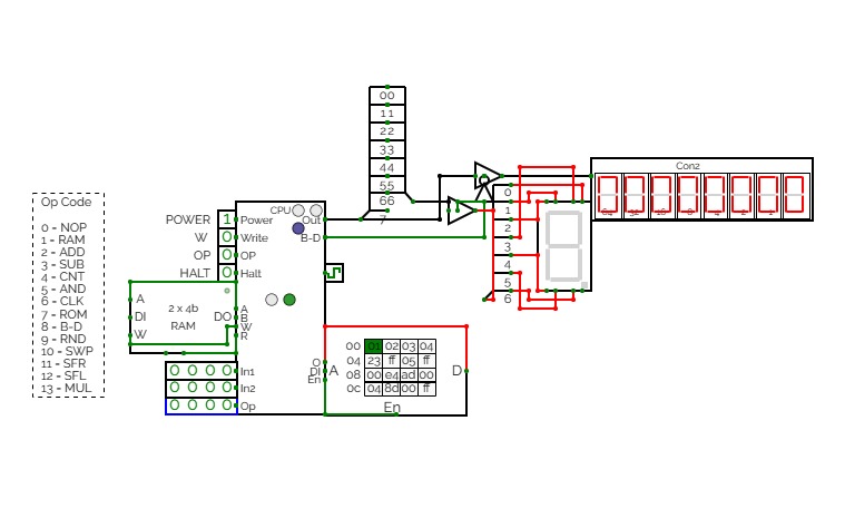
CTH-10 CPUThis is the CTH-10 CPU. By CrEePeRz24321. (most updated version of the CTH Series) This uses all binary to operate. First click on Power to start. Turn Op to 1 and double click the RAM. Then type in the Op code you want. Only put inputs and read outputs of the User Interface. Wait until the Red light turns Green then start. If you want to change operations, then turn Op to 1 and double click the RAM. Then type in the Op code you want. (If you use full screen, and it keeps on kicking you out when you type, click full screen and then look to the bottom right and press + or - and don't touch the full screen after that unless the RAM input kicks you out)
0 is No Operation - Inputs unavailable
1 is RAM - write the address into In1, write the number you want to store into In2 and press Write.
2 is ADD - write the first digit into In1, write the second digit into In2
3 is Subtract - write the first digit into In1, write the second digit into In2
4 is Counter - Inputs unavailable
5 is AND Gate - write the first digit into In1, write the second digit into In2
6 is a Clock - Inputs unavailable
7 is Accessing the ROM - Inputs unavailable
8 is Binary to Decimal converter
9 is Random Number - Inputs unavailable
10 is Not Gate - write the converting digit into In1
11 is Shift Right* - write the converting digit into In1, write the shift number into In2
12 is Shift Left* - write the converting digit into In1, write the shift number into In2
13 is Multiply - write the first digit into In1, write the second digit into In2
14 is Divide - write the first digit into In1, write the second digit into In2**
HALT is to halt operation
*when using shift the first 3 digits of Out will be nonfunctional
**when using divide the first 4 digits away from the CPU are remainders and the last 4 digits closest to the CPU are quotients.
(There is also a Computer version that doesn't get updated much.)
CTH-10
CTH-10This is the CTH-10 CPU. This uses all binary to operate. First click on Power to start. Turn Op to 1 and double click the RAM. Then type in the Op code you want. Only put inputs and read outputs of the User Interface. Wait until the Red light turns Green then start. If you want to change operations, then turn Op to 1 and double click the RAM. Then type in the Op code you want. (If you use full screen, and it keeps on kicking you out when you type, click full screen and then look to the bottom right and press + or - and don't touch the full screen after that unless the RAM input kicks you out)
0 is No Operation - Inputs unavailable
1 is RAM - write the address into In1, write the number you want to store into In2 and press Write.
2 is ADD - write the first digit into In1, write the second digit into In2
3 is Subtract - write the first digit into In1, write the second digit into In2
4 is Counter - Inputs unavailable
5 is AND Gate - write the first digit into In1, write the second digit into In2
6 is a Clock - Inputs unavailable
7 is Accessing the ROM - Inputs unavailable
8 is Binary to Decimal converter
9 is Random Number - Inputs unavailable
10 is Not Gate - write the converting digit into In1
11 is Shift Right* - write the converting digit into In1, write the shift number into In2
12 is Shift Left* - write the converting digit into In1, write the shift number into In2
13 is Multiply - write the first digit into In1, write the second digit into In2
HALT is to halt operation
*when using shift the first 3 digits of Out will be nonfunctional
12 hour clock
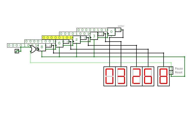
12 hour clockThis is a 12 hour clock with hh/mm/ss/ampm. This is for a final project in EGR 109.60 fall semester.









.jpg)
