I finally did it.
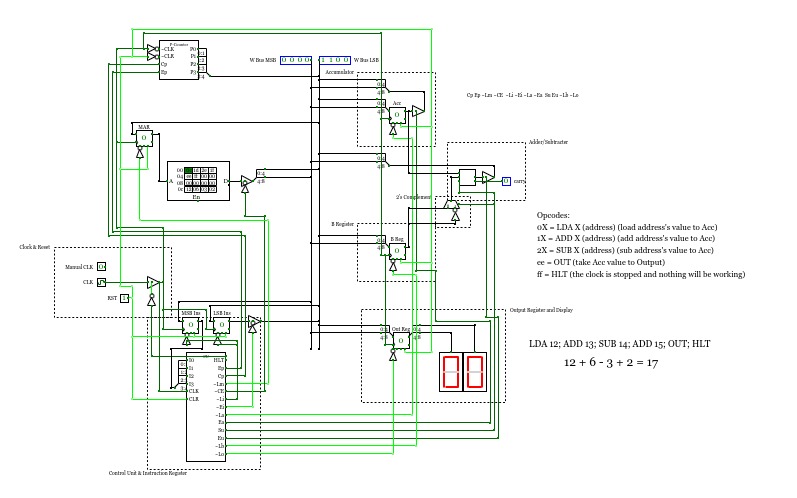
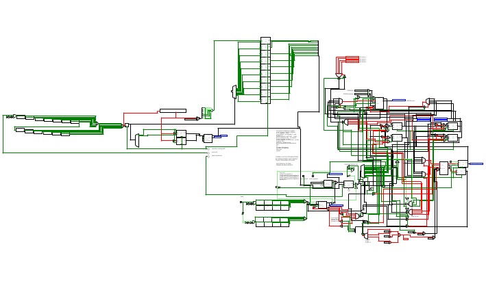
I made my own 8-bit CPU! With a bit of inspiration from other CircuitVerse projects and from a book called, Digital Computer Electronics.
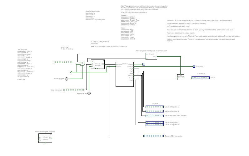
The premade program does this: 12 + 6 - 3 + 2 (which equals 17)
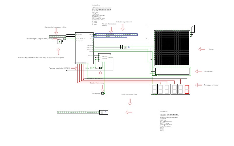
program the computer by typing in the opcodes in the ROM
Opcodes: (X = address)
0X = Load X's value to Accumulator
1X = Add X's value to Accumulator
2x = Subtract X's value from Accumulator
ee = Take Accumulator's value and put it in the Output
ff = Halt/stop everything
Versions (Date format: DD/MM)
9/11 v1.0 - Finally finished it!
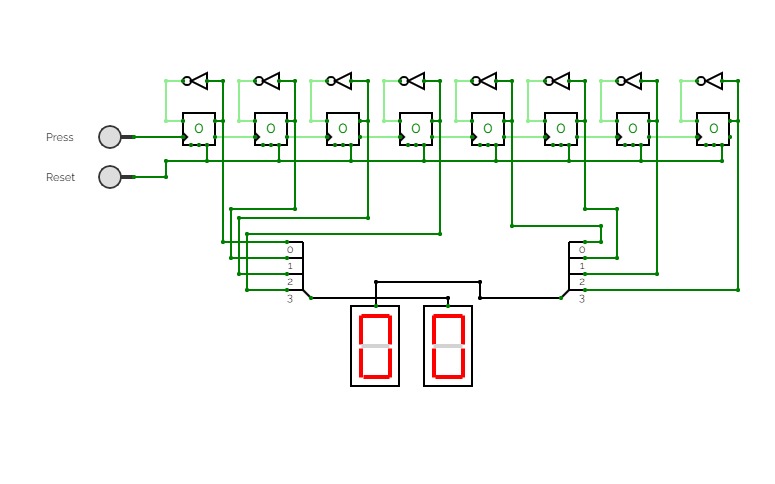
8-bit Asynchronous Counter with Hex Display
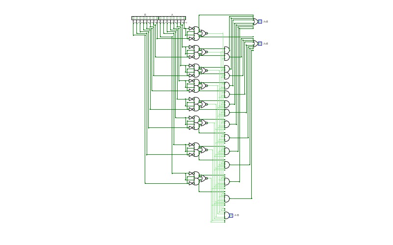
8-bit Asynchronous Counter with Hex Display8-Bit Magnitude Comparator
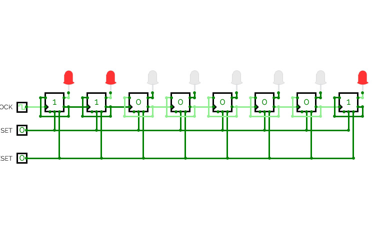
8-Bit Magnitude ComparatorAsynchronous Up Counter 8 bit
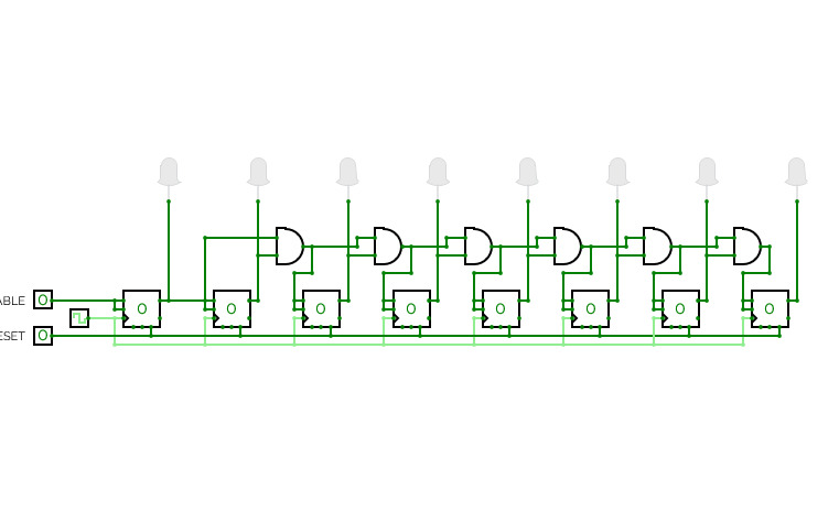
Asynchronous Up Counter 8 bitSynchronous Up Counter 8 bit with Enable and Reset buttons
Synchronous Up Counter 8 bit with Enable and Reset buttons8-bit full adder
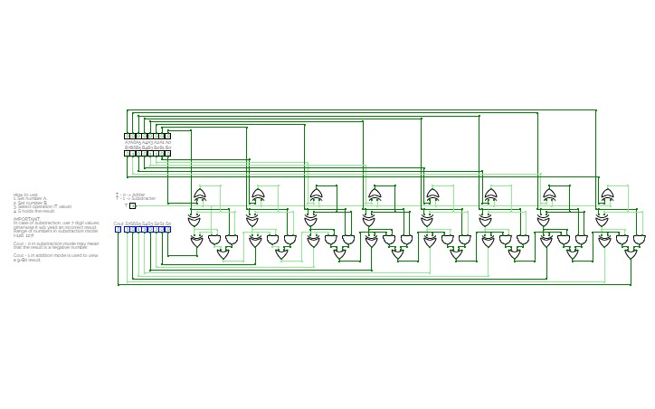
8-bit full adderA simple 8-bit full adder / substractor.
S will compute the result of A + B or A - B
Use 7 bit numbers in subtraction mode (at least for B, to prevent an overflow).
Burtonable Fortitudo
Burtonable FortitudoUSE ON A COMPUTER
Same as V2 exempt that there is a Jump if zero command
JO: Jumps if the ALU output is 0
And you can under stand things better!
(these instructions arent done)
Binary Adders
Binary AddersA collection of binary adders with Binary, Hex, and Decimal input and output representation
8-bit Arithmetic Logic Unit (2
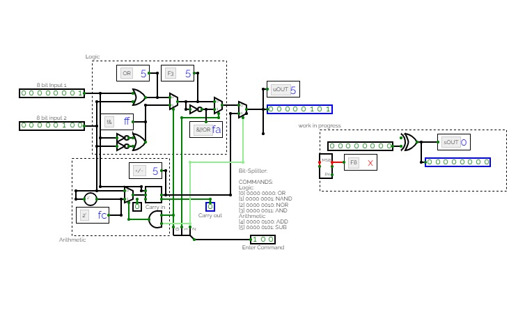
8-bit Arithmetic Logic Unit (2A simple 8-bit arithmetic logical unit.
The following commands are implemented:
Logic Operations:
[0] 000: OR
[1] 001: NAND
[2] 010:NOR
[3] 011: AND
Arithmetic Operations:
[4] 100: ADD
[5] 101: SUB
The two's complement for subtraction is implemented with a NOT Gate and an adder (which simply adds 1 to the negated input).
8-bit Arithmetic Logic Unit (ALU)
8-bit Arithmetic Logic Unit (ALU)A simple 8-bit arithmetic logical unit.
The following commands are implemented:
Logic Operations:
[0] 000: OR
[1] 001: NAND
[2] 010:NOR
[3] 011: AND
Arithmetic Operations:
[4] 100: ADD
[5] 101: SUB
The two's complement for subtraction uses the built in component.
8-Bit Computer with Complex Lanes
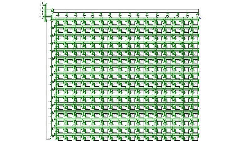
8-Bit Computer with Complex LanesFollowed the instruction of the 8-Bit Computer YouTube video series by Ben Eater. I also extended it's functionalities a little bit by upgrading from 16 bytes to 256 bytes of RAM and I added a Micro Step Counter Reset (SCR) instruction signal to allow operations to finish earlier.
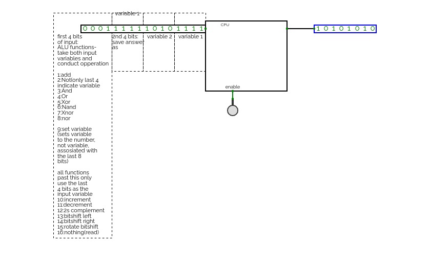
A CPU! this took me a while to figure out, mostly how to get it to run comands, but I eventually found a solution of using 4 bits as function indicators, 4 as where to save the output, 4 as the 2nd input, and 4 as the first input!
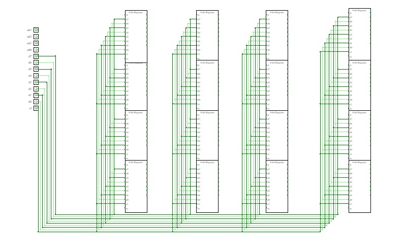
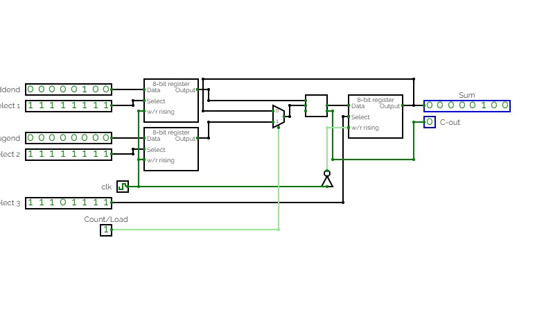
Adjustable 8-bit adder which either loads values from two different registers into an 8-bit adder or sequentially adds the current output value of the adder to the value stored in the first register. Practice for RAM unit application, register creation and organization, bit splitting and compression, and sequential logic.
Project3
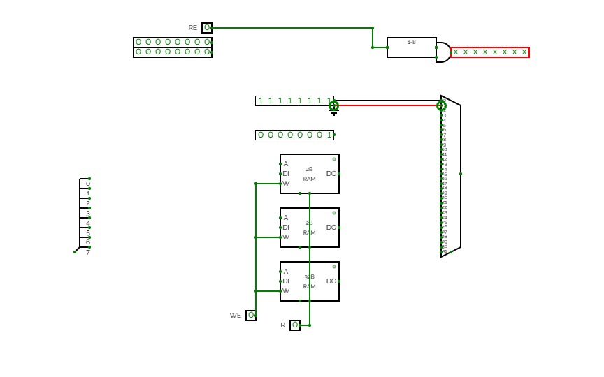
Project3An attempt at utilizing memory storage to create some output based on information inputted into ROM block; output changes when ROM enable is toggled while the address input counter changes to change up the sequence of input bits to the registers.
