
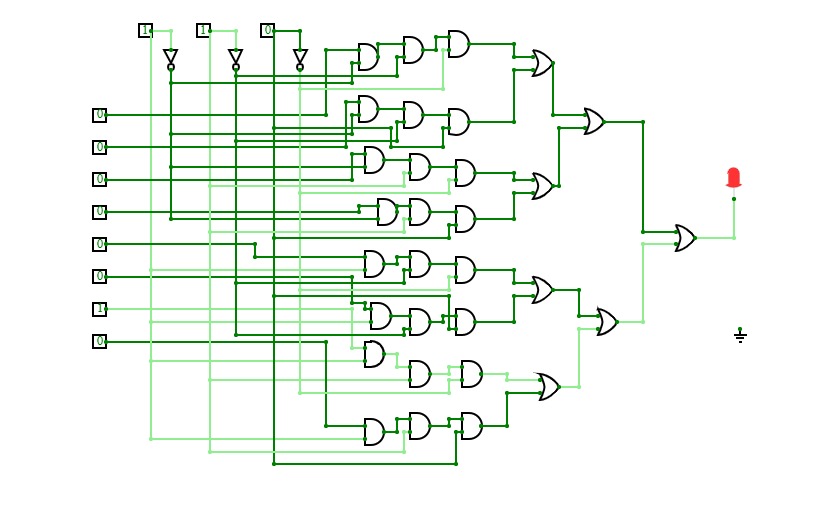

8x1 Multiplexer
8x1 Multiplexer8x1 multiplexer has 8 data input lines I0, I1, I2, I3, I4, I5, I6, I7, 3 select lines S0, S1, S2 and one output, Y.
Truth Table for 8x1 Multiplexer
Data Select Input
Output
Y
S2
S1
S0
0
0
0
I0
0
0
1
I1
0
1
0
I2
0
1
1
I3
1
0
0
I4
1
0
1
I5
1
1
0
I6
1
1
1
I7
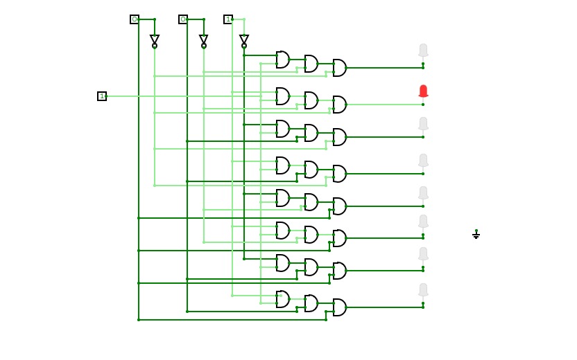
De Multiplexer
De Multiplexer1x8 de multiplexer has 1 input line I, 3 select lines S0,
S1, S2 and 8 outputs Y0, Y1, Y2,
Y3, Y4,Y5,
Y6, Y7
Truth Table of 1x8 DE MUX
Input
Data
S2
S1
S0
Y0
Y1
Y2
Y3
Y4
Y5
Y6
Y7
D
0
0
0
D
0
0
0
0
0
0
0
D
0
0
1
0
D
0
0
0
0
0
0
D
0
1
0
0
0
D
0
0
0
0
0
D
0
1
1
0
0
0
D
0
0
0
0
D
1
0
0
0
0
0
0
D
0
0
0
D
1
0
1
0
0
0
0
0
D
0
0
D
1
1
0
0
0
0
0
0
0
D
0
D
1
1
1
0
0
0
0
0
0
0
D
set and reset
set and reset
store data
store data

.jpg)
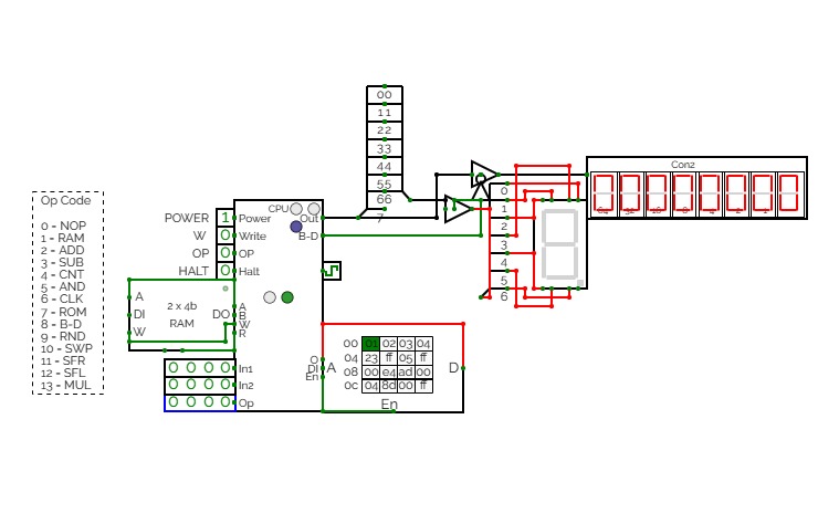
CTH-10 CPU
CTH-10 CPUThis is the CTH-10 CPU. By CrEePeRz24321. (most updated version of the CTH Series) This uses all binary to operate. First click on Power to start. Turn Op to 1 and double click the RAM. Then type in the Op code you want. Only put inputs and read outputs of the User Interface. Wait until the Red light turns Green then start. If you want to change operations, then turn Op to 1 and double click the RAM. Then type in the Op code you want. (If you use full screen, and it keeps on kicking you out when you type, click full screen and then look to the bottom right and press + or - and don't touch the full screen after that unless the RAM input kicks you out)
0 is No Operation - Inputs unavailable
1 is RAM - write the address into In1, write the number you want to store into In2 and press Write.
2 is ADD - write the first digit into In1, write the second digit into In2
3 is Subtract - write the first digit into In1, write the second digit into In2
4 is Counter - Inputs unavailable
5 is AND Gate - write the first digit into In1, write the second digit into In2
6 is a Clock - Inputs unavailable
7 is Accessing the ROM - Inputs unavailable
8 is Binary to Decimal converter
9 is Random Number - Inputs unavailable
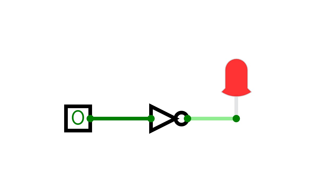
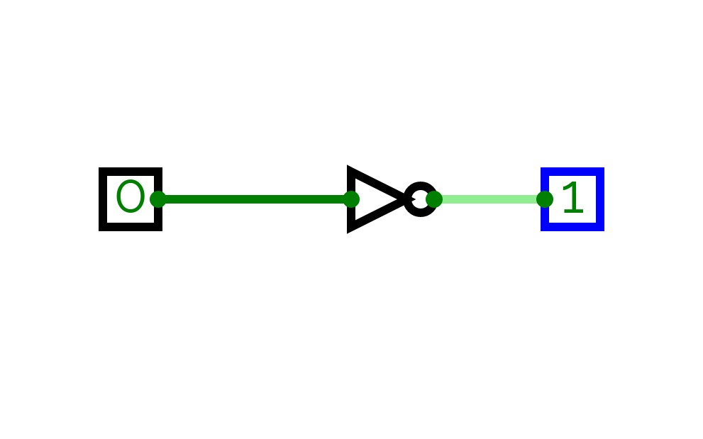
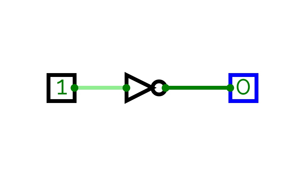
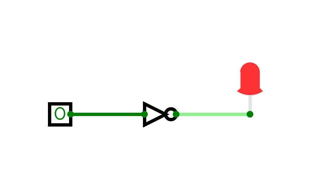
10 is Not Gate - write the converting digit into In1
11 is Shift Right* - write the converting digit into In1, write the shift number into In2
12 is Shift Left* - write the converting digit into In1, write the shift number into In2
13 is Multiply - write the first digit into In1, write the second digit into In2
14 is Divide - write the first digit into In1, write the second digit into In2**
HALT is to halt operation
*when using shift the first 3 digits of Out will be nonfunctional
**when using divide the first 4 digits away from the CPU are remainders and the last 4 digits closest to the CPU are quotients.
(There is also a Computer version that doesn't get updated much.)
CTH-10
CTH-10This is the CTH-10 CPU. This uses all binary to operate. First click on Power to start. Turn Op to 1 and double click the RAM. Then type in the Op code you want. Only put inputs and read outputs of the User Interface. Wait until the Red light turns Green then start. If you want to change operations, then turn Op to 1 and double click the RAM. Then type in the Op code you want. (If you use full screen, and it keeps on kicking you out when you type, click full screen and then look to the bottom right and press + or - and don't touch the full screen after that unless the RAM input kicks you out)
0 is No Operation - Inputs unavailable
1 is RAM - write the address into In1, write the number you want to store into In2 and press Write.
2 is ADD - write the first digit into In1, write the second digit into In2
3 is Subtract - write the first digit into In1, write the second digit into In2
4 is Counter - Inputs unavailable
5 is AND Gate - write the first digit into In1, write the second digit into In2
6 is a Clock - Inputs unavailable
7 is Accessing the ROM - Inputs unavailable
8 is Binary to Decimal converter
9 is Random Number - Inputs unavailable
10 is Not Gate - write the converting digit into In1
11 is Shift Right* - write the converting digit into In1, write the shift number into In2
12 is Shift Left* - write the converting digit into In1, write the shift number into In2
13 is Multiply - write the first digit into In1, write the second digit into In2
HALT is to halt operation
*when using shift the first 3 digits of Out will be nonfunctional


