Two 3-bit number Adder
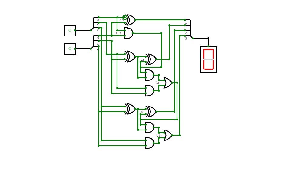
Two 3-bit number AdderA circuit that adds two 3-bit numbers using a half-adder and a full-adder.
A circuit that takes two decimal numbers A and B as input and then splits in into their corresponding three bits using a splitter and then calculates their summation using XOR, AND and OR gates. This generates 4 output lines for 4 bits of the summation, and a reversed splitter is finally used to join the output lines to produce a 4-bit output and displayed using a Hex-Display.
This is a ripple-carry adder.
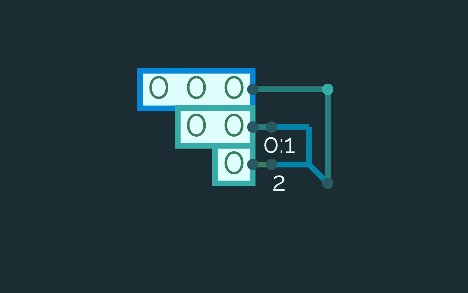
Why multiple splitters are problematic.
Why multiple splitters are problematic.This is a simple explanation of why you shouldn't use multiple splitters (or as someone else called them "splitter trees") in a row. The way to uneven split is simply 2 1 or any variation. Sadly when using larger bit-widths splitter trees are harder to avoid without complicating the whole circuit.
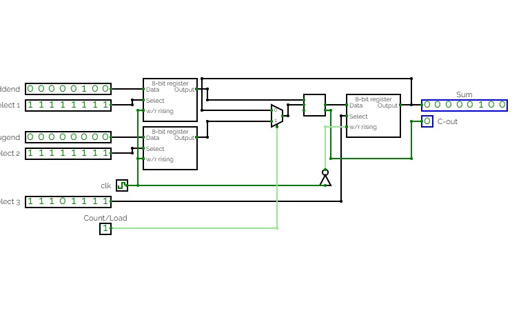
Adjustable 8-bit adder which either loads values from two different registers into an 8-bit adder or sequentially adds the current output value of the adder to the value stored in the first register. Practice for RAM unit application, register creation and organization, bit splitting and compression, and sequential logic.
Project3
Project3An attempt at utilizing memory storage to create some output based on information inputted into ROM block; output changes when ROM enable is toggled while the address input counter changes to change up the sequence of input bits to the registers.
