

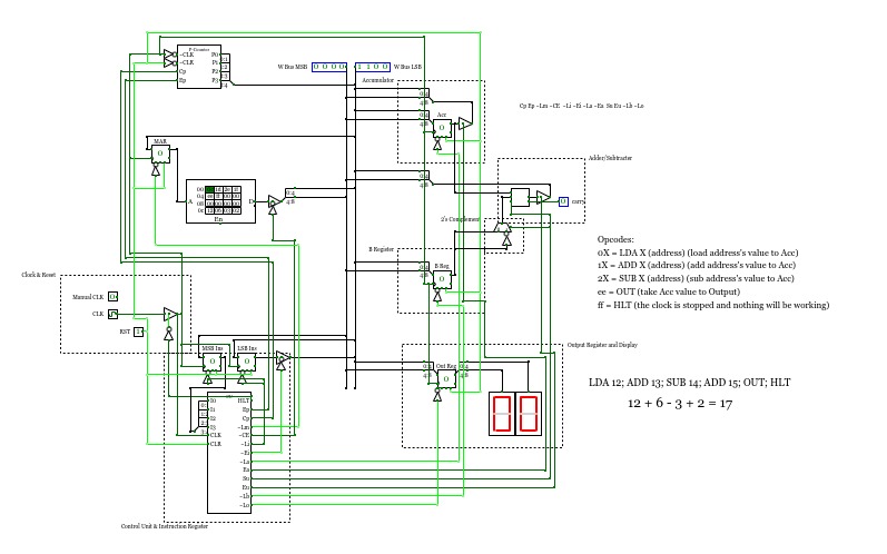
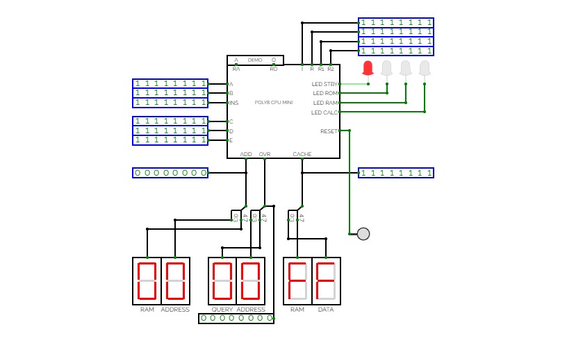
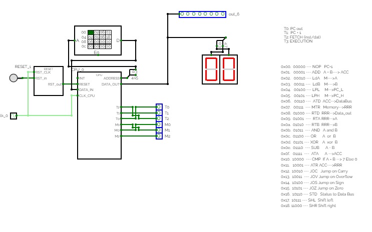
SAP-1
SAP-1- LDA - 0 - Load RAM data into accumulator
- ADD - 1 - Add RAM data to accumulator
- SUB - 2 - Subtract RAM data from accumulator
- OUT - e - Load accumulator data into output register
- HLT - f - Stop processing
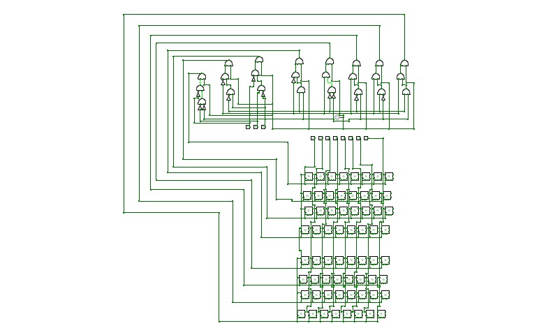
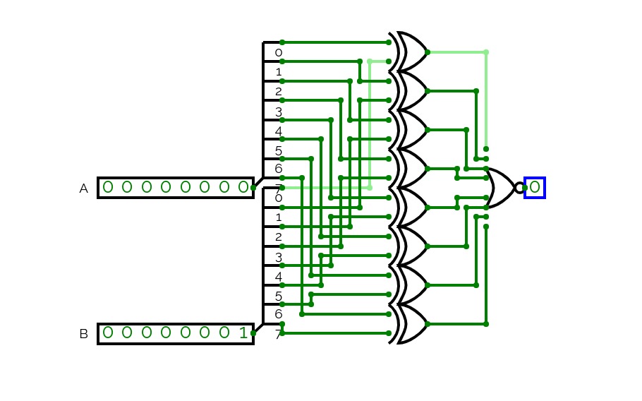
DED for 8-bit data using Hamming code
DED for 8-bit data using Hamming codeDED for 8-bit data using Hamming code
A computer made completely out of logic gates. Version 2. V1 can be found here: https://circuitverse.org/users/13948/projects/49969
Because of the limitations of the circuitverse.org simulator, and for easier use, some inbuilt components are used (like the 256-byte RAM module), but most of it is made up of OR, AND, NOT, XOR, NOR and NAND.
This project was originally made for my profile project. This is (or will be) version 2 of the 8-bit computer.
I finally did it.
I made my own 8-bit CPU! With a bit of inspiration from other CircuitVerse projects and from a book called, Digital Computer Electronics.
The premade program does this: 12 + 6 - 3 + 2 (which equals 17)
program the computer by typing in the opcodes in the ROM
Opcodes: (X = address)
0X = Load X's value to Accumulator
1X = Add X's value to Accumulator
2x = Subtract X's value from Accumulator
ee = Take Accumulator's value and put it in the Output
ff = Halt/stop everything
Versions (Date format: DD/MM)
9/11 v1.0 - Finally finished it!
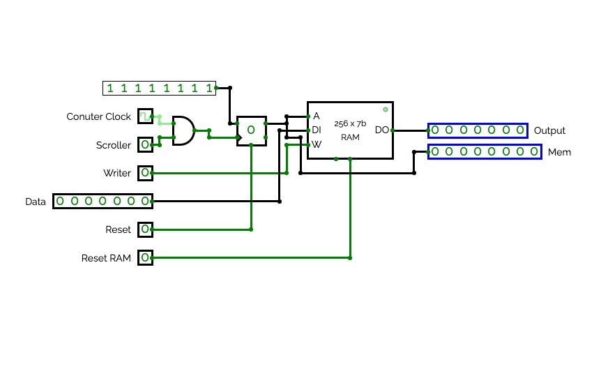
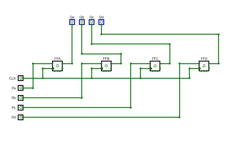
BRWD: BINARY READER AND WRITER DEVICE
Specs:
7-bit RAM
8-bit Memory
How to use:
1. To start writing, set your clock speed, and turn on the "Writer" switch.
2. To scroll through the memory, turn on the "Scroll" switch. Press "Reset" if you are ready to read.
3. Turn the "Writer" switch off, and turn on "Scroll" to start reading the binary.
4. Then when you're done, press "Reset RAM" to reset your writing.
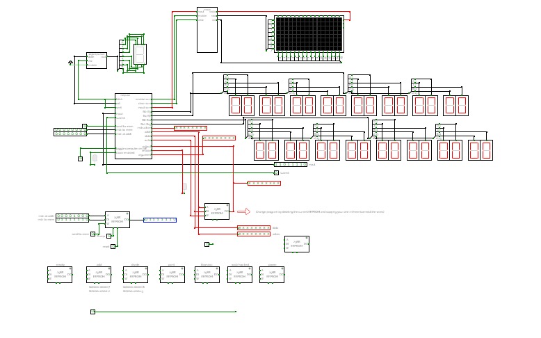
8-bit Microcomputer v1.9
8-bit Microcomputer v1.9Under construction.
8-bit Microcomputer v1.5
8-bit Microcomputer v1.5Under construction.
8-bit Microcomputer v2.0
8-bit Microcomputer v2.0Under construction.
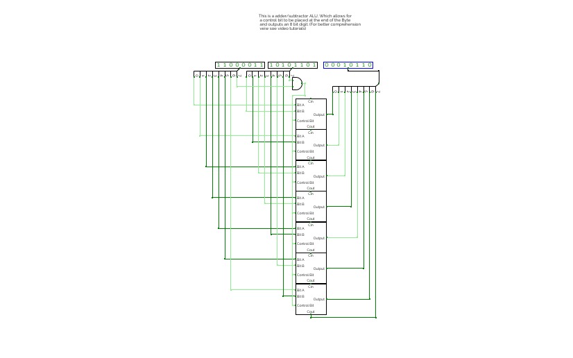
Features a single-bit adder and subtractor as well as a combination of the two. Also showcases a 4-bit adder/subtractor and an 8-bit ALU adder subtractor.
(If anything in the description is wrong please feel free to say so in the comments.


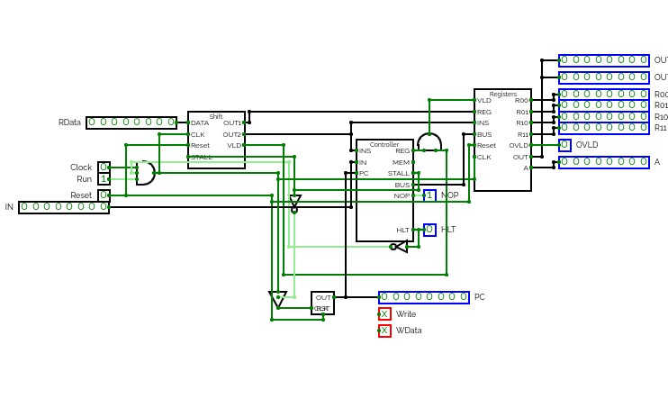
Femboy-8
Femboy-8
FEMBOY-8
Functional Electronic Machine Binary Operator Yes
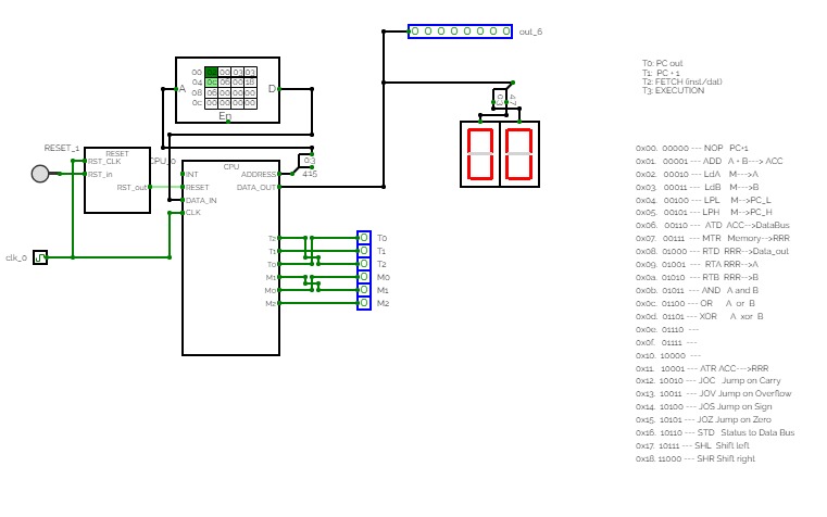
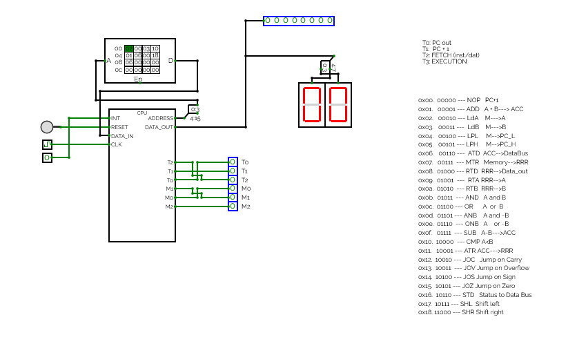
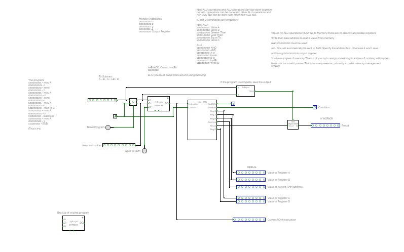
8-bit CPU
Working on a NEW CPU: Femboy-16!
ASSEMBLER:
https://output.jsbin.com/wutikij
GPU:
https://circuitverse.org/users/214464/projects/cb-ppu
INSTRUCTION SET:
00: NOP - Nothing
01: HLT - Halt program
02: OUT [id] - Output the accumulator out of an output
03: LDI A, [d8] - Loads immediate 8 bit word into the accumulator
04: MOV [r], A - Move register to accumulator
05: MOV A, [r] - Move accumulator to register
06: INC [r] - Increment a register
07: DEC [r] - Decrememt a register
08: ADD [r], A - Add the accumulator from a register
09: SUB [r], A - Subtract the accumulator from a register
0A: AND [r], A - And the register and accumulator
0B: IOR [r], A - OR the register and accumulator
0C: XOR [r], A - XOR the register and accumulator
0D: NOT [r] - NOT a register
0E: SRR [r] - Barrel shift accumulator right
0F: SRL [r] - Barrel shift accumulator left
10: JUP [d8] - Jump to a location
11: JPP [r] - Jump to a register value
12: JPL A, [d8] - Jump if accumulator is less than 0
13: JZO A, [d8] - Jump if accumulator is 0
14: JPG A, [d8] - Jump if accumulator is greater than 0
15: JLE A, [d8] - Jump if accumulator is less than or equal to 0
16: JGE A, [d8] Jump if accumulator is greater than or equal to 0
17: JNZ A, [d8] Jump if accumulator is not 0
18: CLR [r] - Clear a register
19: INP [id] - Store INPUT id in accumulator
1A: MOV pA, [r] - Move the value at address A register r
1B: MOV [r], pA - Move register r into address A
1C: MOV [p], A - Move a value in a pointer to the accumulator
1D: MOV A, [p] - Move the accumulator to a location
1E: MLT [r], A - Multiply register r by the accumulator
1F: DIV [r], A - Divide register r by accumulator
REGISTERS:
00: REGISTER 1
01: REGISTER 2
02: REGISTER 3
04: REGISTER 4
05: ZERO FLAG (R)
06: PC (R)
07: ALU Result (R)
Update Notes:
V4:
So this is the 4th iteration of my CPU lol... I added a few programs for you all to try out and you can even use an assembler now!
V5:
Long time since I updated this... But I've added a GPU! It's called "Color burst" and you can go try out some premade programs I have added on it! There's an assembler guide with GPU dev guide and I encourage you all to go try and make some graphical programs! Also more docs can be found on it's project page.
To-Do:
Increase amount of registers to 8
Make a simple command line
Make a simple operating system for the CPU
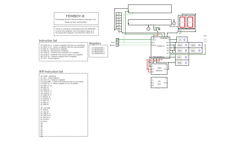
Functional Electronic Machine Binary Operator Yes - 8-bit cpu
This is a work in progress right now.
INSTRUCTION SET:
00: MOV [r], A - Loads a register into the accumulator.
01: MOV A, [r] - Saves a register into the accumulator.
02: INC [r] - Increment a register
03: DEC [r] - Decrement a register
04: ADD [r] - Add the accumulator to a register
05: SUB [r] - Subtract the accumulator to a register
06: OUT [r] - Output a signal from a register
07: HLT - End program
REGISTERS:
00: REGISTER 1
01: REGISTER 2
02: REGISTER 3
04: REGISTER 4
Update Notes:
Final design before update of is a.
To-Do:
Add WIP instructions
Add the accumulator to a register address
Increase amount of registers to 8
Add Ram manipulation instructions
Add Input to CPU
Add more operations to the ALU
Add ASCII i/o
Make a simple command line
Make an assember
Make a simple operating system for the cpu
Add rgb output
Functional Electronic Machine Binary Operator Yes - 8-bit cpu
This is a work in progress right now.
INSTRUCTION SET:
00: NOP - Nothing
01: HLT - Halt program
02: OUT [r] - Output a register
03: LDA [d8] - Loads 8 bit data into the accumulator
04: MOV [r], A - Move register to accumulator
05: MOV A, [r] - Move accumulator to register
06: INC [r] - Increment a register
07: DEC [r] - Decrememt a register
08: ADD [r], A - Add the accumulator from a register
09: SUB [r], A - Subtract the accumulator from a register
0A: AND [r], A - And the register and accumulator
0B: IOR [r], A - OR the register and accumulator
0C: XOR [r], A - XOR the register and accumulator
0D: NOT [r] - NOT a register
0E: SRR [r] - Shift register right
0F: SRL [r] - Shift register Left
REGISTERS:
00: REGISTER 1
01: REGISTER 2
02: REGISTER 3
04: REGISTER 4
Update Notes:
The instruction set now has 16 instructions with logic operations, loading, shift, and nop.
To-Do:
Add WIP instructions
Add the accumulator to a register address
Increase amount of registers to 8
Add Ram manipulation instructions
Add Input to CPU
Add more operations to the ALU
Add ASCII i/o
Make a simple command line
Make an assember
Make a simple operating system for the cpu
Add rgb output
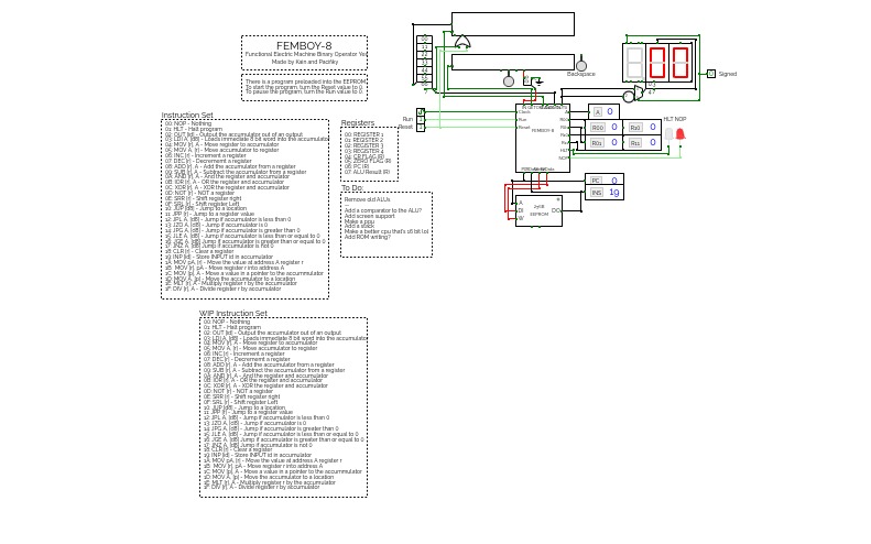
FEMBOY-8v1.3
FEMBOY-8v1.3Functional Electronic Machine Binary Operator Yes - 8-bit cpu
This is a work in progress right now.
INSTRUCTION SET:
00: NOP - Nothing
01: HLT - Halt program
02: OUT [id] - Output the accumulator out of an output
03: LDI A, [d8] - Loads immediate 8 bit word into the accumulator
04: MOV [r], A - Move register to accumulator
05: MOV A, [r] - Move accumulator to register
06: INC [r] - Increment a register
07: DEC [r] - Decrememt a register
08: ADD [r], A - Add the accumulator from a register
09: SUB [r], A - Subtract the accumulator from a register
0A: AND [r], A - And the register and accumulator
0B: IOR [r], A - OR the register and accumulator
0C: XOR [r], A - XOR the register and accumulator
0D: NOT [r] - NOT a register
0E: SRR [r] - Shift register right
0F: SRL [r] - Shift register Left
10: JUP [d8] - Jump to a location
11: JPP [r] - Jump to a register value
12: JPL A, [d8] - Jump if accumulator is less than 0
13: JZO A, [d8] - Jump if accumulator is 0
14: JPG A, [d8] - Jump if accumulator is greater than 0
15: JLE A, [d8] - Jump if accumulator is less than or equal to 0
16: JGE A, [d8] Jump if accumulator is greater than or equal to 0
17: JNZ A, [d8] Jump if accumulator is not 0
18: CLR [r] - Clear a register
19: INP [id] - Store INPUT id in accumulator
1A: MOV pA, [r] - Move the value at address A register r
1B: MOV [r], pA - Move register r into address A
1C: MOV [p], A - Move a value in a pointer to the accumulator
1D: MOV A, [p] - Move the accumulator to a location
1E: MLT [r], A - Multiply register r by the accumulator
1F: DIV [r], A - Divide register r by accumulator
REGISTERS:
00: REGISTER 1
01: REGISTER 2
02: REGISTER 3
04: REGISTER 4
05: ZERO FLAG (R)
06: PC (R)
07: ALU Result (R)
Update Notes:
Welcome to the 3rd iteration of my Femboy-8 CPU! This might be the last version with 32 instructions.
To-Do:
Increase amount of registers to 8
Make a simple command line
Make an assember
Make a simple operating system for the CPU
Add rgb output
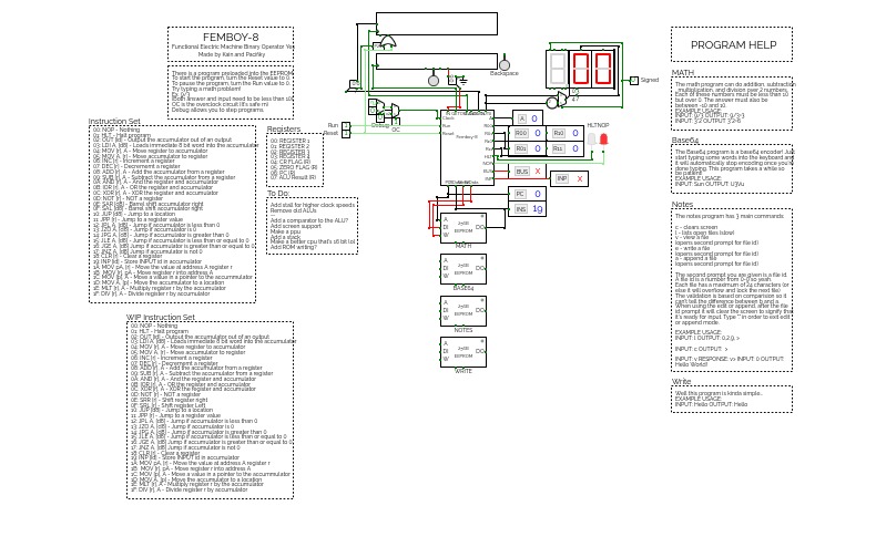
FEMBOY-8V1.4
FEMBOY-8V1.4Functional Electronic Machine Binary Operator Yes - 8-bit cpu
Working on a new CPU: Femboy-16
ASSEMBLER:
https://output.jsbin.com/wutikij
INSTRUCTION SET:
00: NOP - Nothing
01: HLT - Halt program
02: OUT [id] - Output the accumulator out of an output
03: LDI A, [d8] - Loads immediate 8 bit word into the accumulator
04: MOV [r], A - Move register to accumulator
05: MOV A, [r] - Move accumulator to register
06: INC [r] - Increment a register
07: DEC [r] - Decrememt a register
08: ADD [r], A - Add the accumulator from a register
09: SUB [r], A - Subtract the accumulator from a register
0A: AND [r], A - And the register and accumulator
0B: IOR [r], A - OR the register and accumulator
0C: XOR [r], A - XOR the register and accumulator
0D: NOT [r] - NOT a register
0E: SAR [d8] - Barrel shift accumulator right
0F: SAL [d8] - Barrel shift accumulator left
10: JUP [d8] - Jump to a location
11: JPP [r] - Jump to a register value
12: JPL A, [d8] - Jump if accumulator is less than 0
13: JZO A, [d8] - Jump if accumulator is 0
14: JPG A, [d8] - Jump if accumulator is greater than 0
15: JLE A, [d8] - Jump if accumulator is less than or equal to 0
16: JGE A, [d8] Jump if accumulator is greater than or equal to 0
17: JNZ A, [d8] Jump if accumulator is not 0
18: CLR [r] - Clear a register
19: INP [id] - Store INPUT id in accumulator
1A: MOV pA, [r] - Move the value at address A register r
1B: MOV [r], pA - Move register r into address A
1C: MOV [p], A - Move a value in a pointer to the accumulator
1D: MOV A, [p] - Move the accumulator to a location
1E: MLT [r], A - Multiply register r by the accumulator
1F: DIV [r], A - Divide register r by accumulator
REGISTERS:
00: REGISTER 1
01: REGISTER 2
02: REGISTER 3
04: REGISTER 4
05: ZERO FLAG (R)
06: PC (R)
07: ALU Result (R)
Update Notes:
So this is the 4th iteration of my CPU lol... I added a few programs for you all to try out and you can even use an assembler now!
To-Do:
Increase amount of registers to 8
Make a simple command line
Make an assember
Make a simple operating system for the CPU
Add rgb output
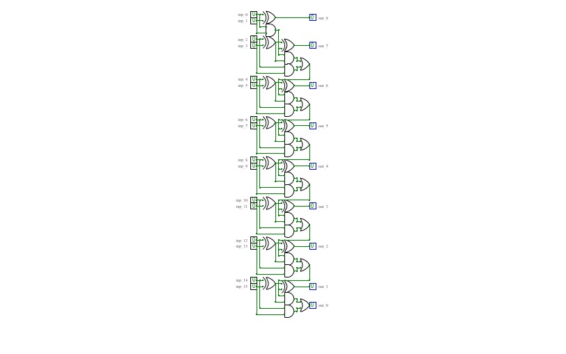
Equality Comparison (8-bit)
Equality Comparison (8-bit)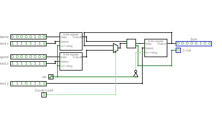
Adjustable 8-bit adder which either loads values from two different registers into an 8-bit adder or sequentially adds the current output value of the adder to the value stored in the first register. Practice for RAM unit application, register creation and organization, bit splitting and compression, and sequential logic.


Project3
Project3An attempt at utilizing memory storage to create some output based on information inputted into ROM block; output changes when ROM enable is toggled while the address input counter changes to change up the sequence of input bits to the registers.


