

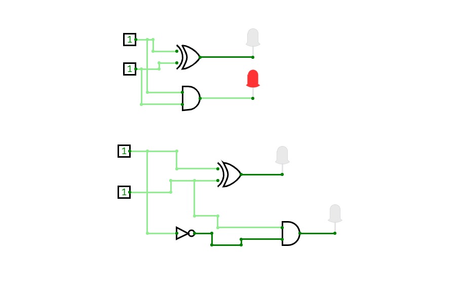
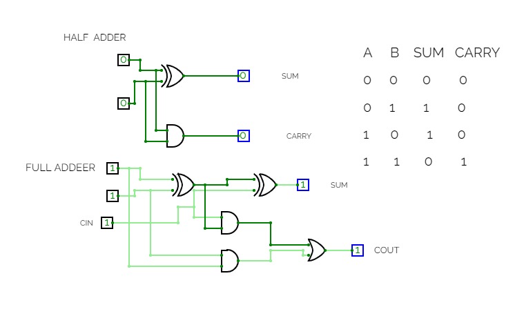
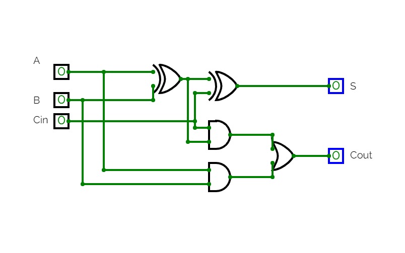
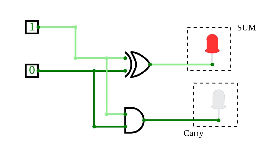
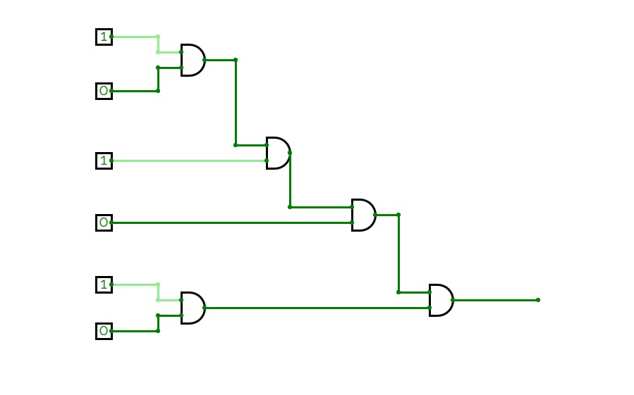
Super Sumador
Super Sumadormamamoo RIFA
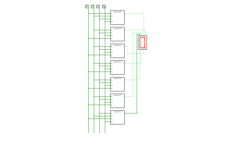
mamamoo RIFADecodificador de display de 7 elementos

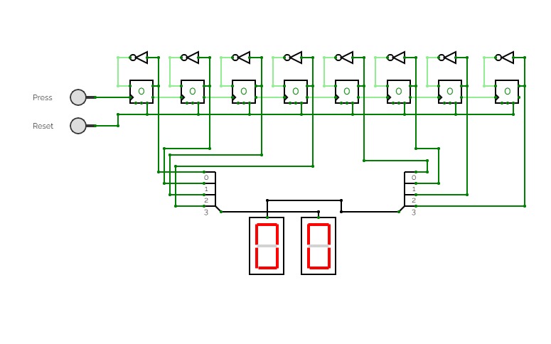
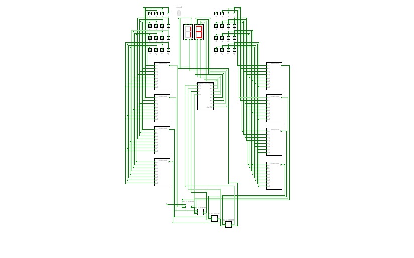
8-bit Asynchronous Counter with Hex Display
8-bit Asynchronous Counter with Hex Display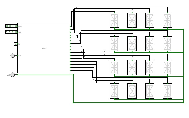
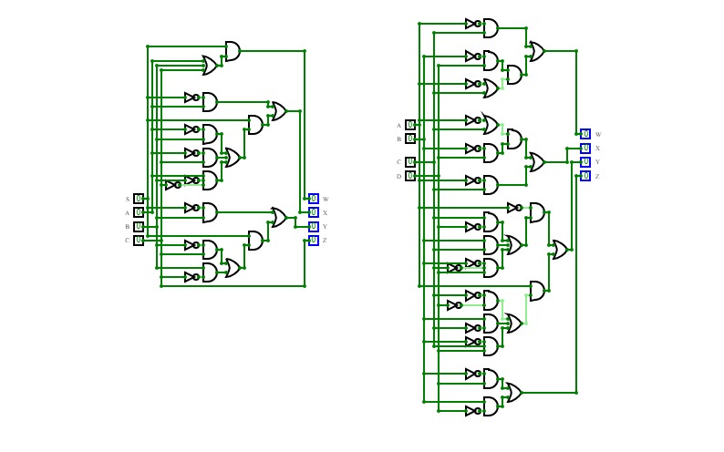
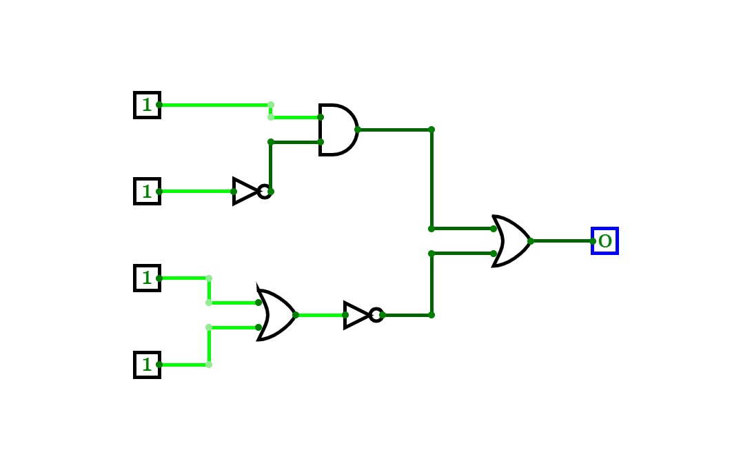
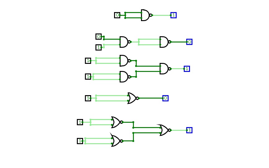
Solucionario Tarea de Simplificación Algebraica
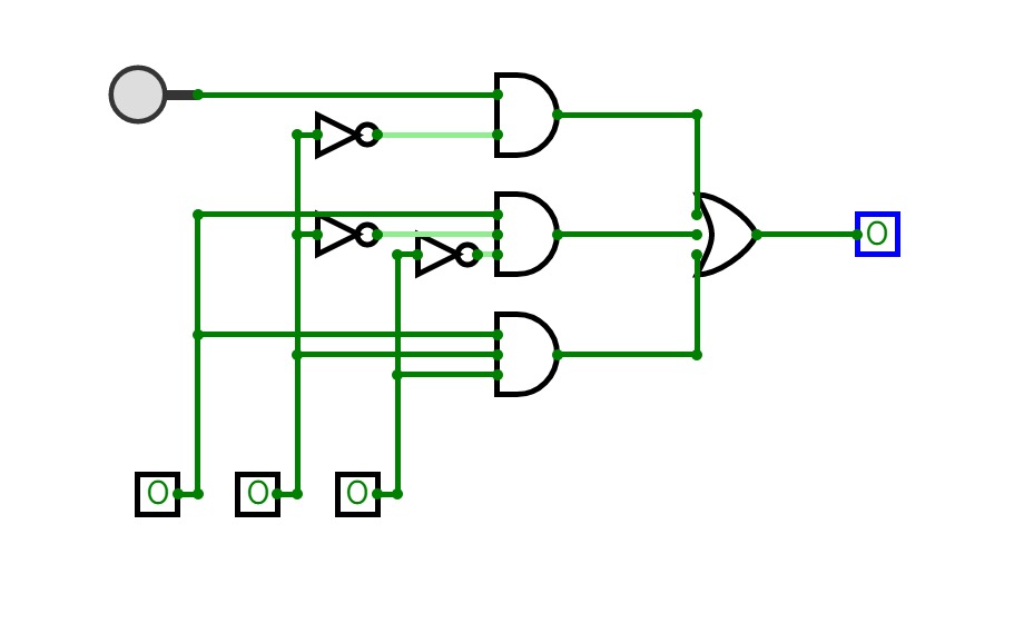
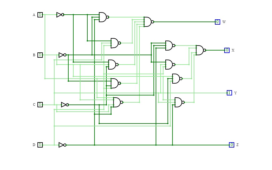
Solucionario Tarea de Simplificación AlgebraicaParte Izquierda: Sea S un bit de signo y ABC un número binario de 3 bits. Haga la tabla de verdad y la simplificación de expresiones tal que SABC = WXYZ sea un número binario de 4 bits en complemento a 2.
Parte Derecha: Sean AB y CD dos números binarios de dos bits. Haga la tabla de verdad y la simplificación de expresiones tal que AB - CD = WXYZ sea un número binario de 4 bits en complemento a 2 que represente la resta.
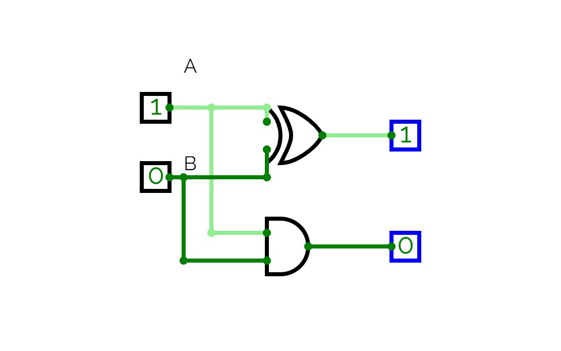
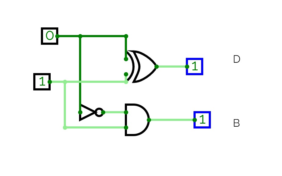
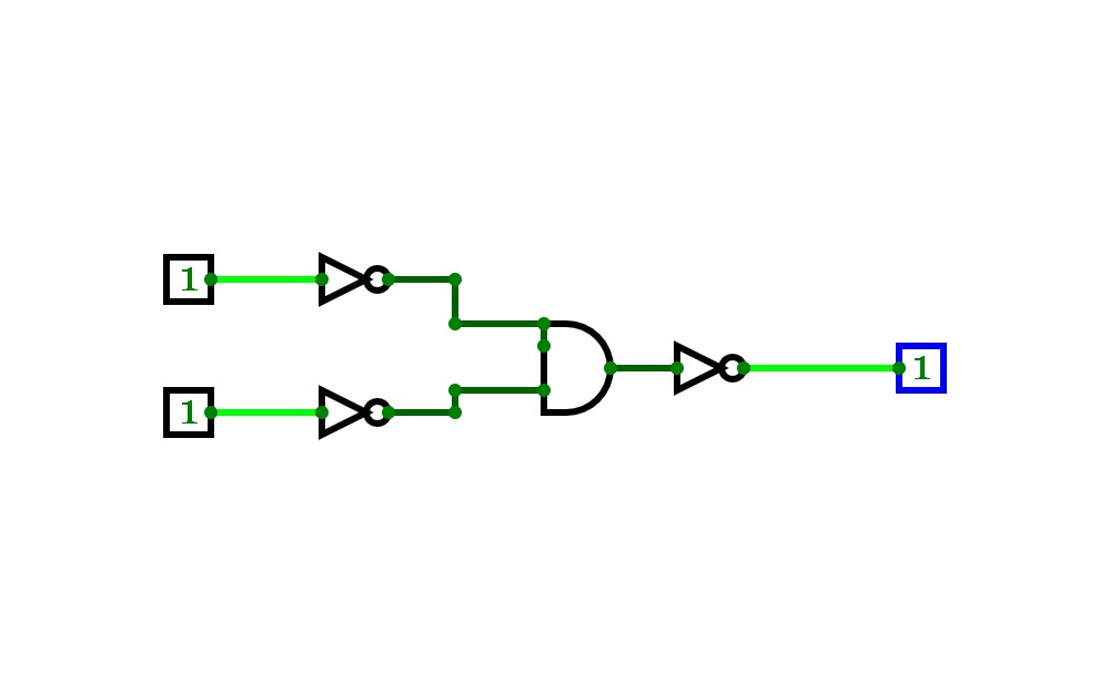
circuit digarm half subrtactor
circuit digarm half subrtactor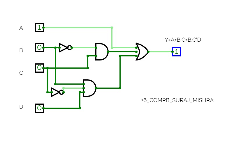

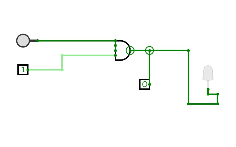
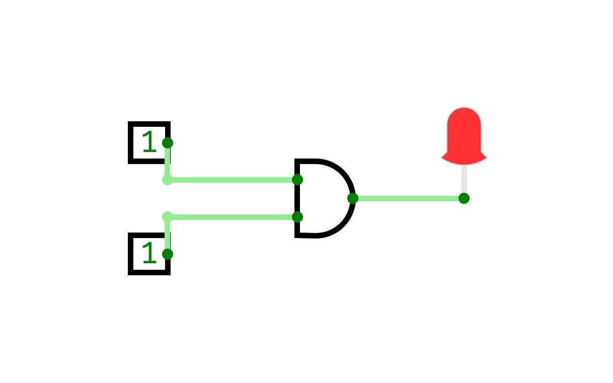
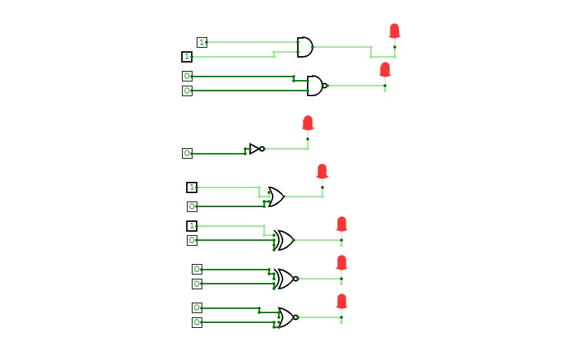
Constant Button
Constant ButtonThis button will stay on (emit signal 1) once clicked. If clicked again, it will output 0.
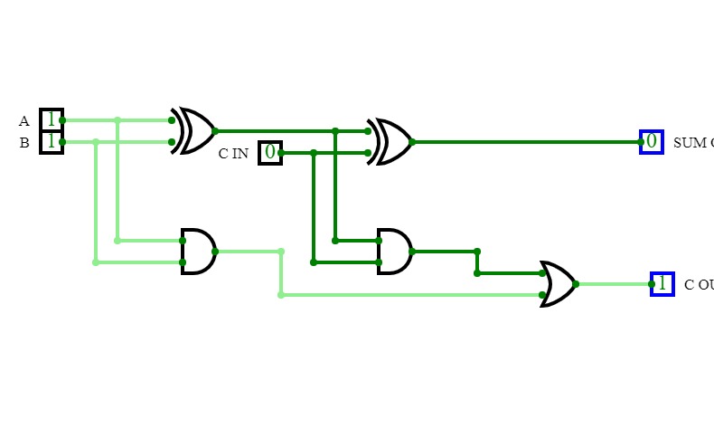

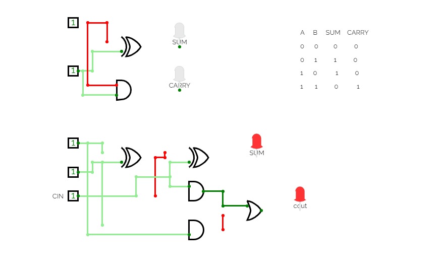
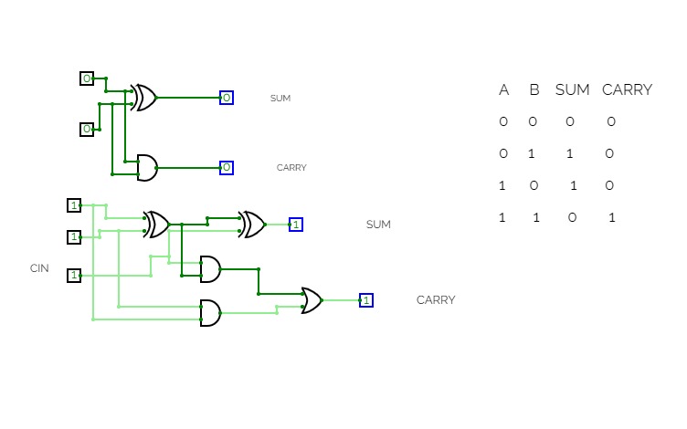
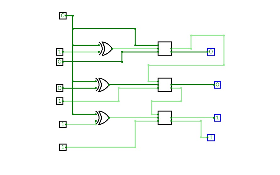
4-bit Adder
4-bit AdderThe 4-bit adder which can do math on 4-bit integers and display on 2 7-segment LEDs.
This project is owned by Lu Xuan Minh - student of HCMUT.
Everyone can fork my project for the purpose of studying and researching.
Thank you for your viewing!
Lu Xuan Minh
Email: [email protected]

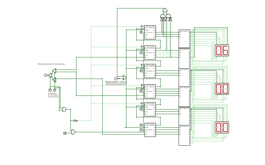
Clock
ClockThis is a simple digital clock with basic combinational and sequential logic circuits.
It can display seconds, minutes, and hours
Users can set time by clicking the button and using the multiplexer to choose which to change.
Also, the design for the 4bits 7segment display and 3 bits 7segment display is inside.
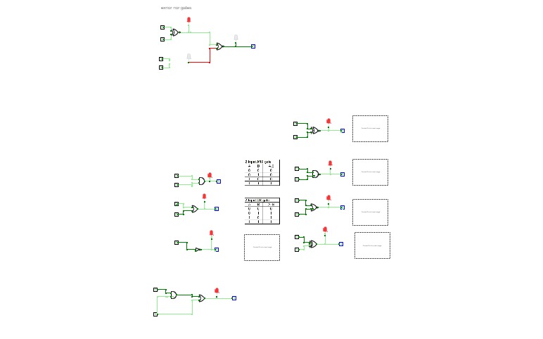
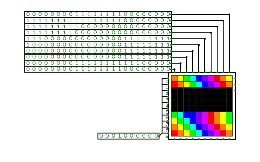
encryption circuit t23 g2
encryption circuit t23 g2ENCRYPTION CIRCUIT TUTORIAL 23 GROUP 2
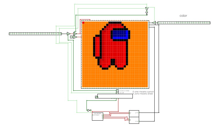
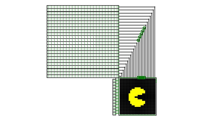
Control the dot/drawer using wasd on the keyboard. Make sure to turn it on using the on switch. You can switch between draw and cursor with the switch. And you can change the color. With these tools you can make almost any 30 by 30 pixel image such as the showcase image. To delete an image just switch to cursor mode and move the dot. To delete a pixel at a time just set the color to 0 and move it to what you want to delete.
For best experience set clock speed to 50.


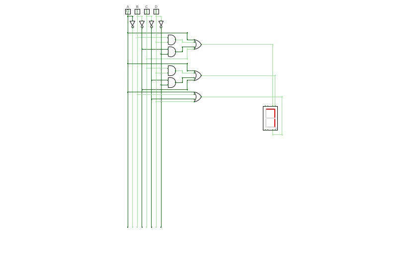
7-Segment Display
7-Segment Display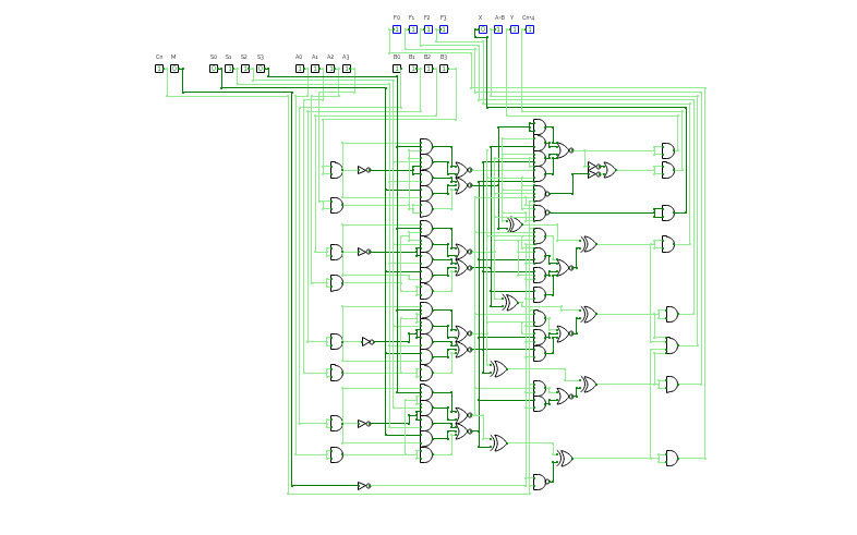
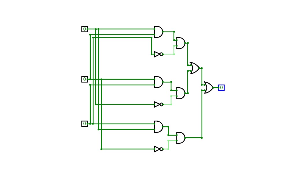
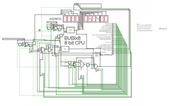
Texas Instruments 74181
Texas Instruments 74181This is a recreation of the eponymous TI circuit for examining it's function. This circuit is an exact copy of the TI chip but with some IO circuitry for visualization. This schematic was created with the intention of using it to debug an emulated version created in a physics sandbox game, Phyzios Studio Pro.


