


This is an example implementation of the uCISC instruction set as defined at https://github.com/grokthis/ucisc. So far it implements the Copy and ALU instructions. Note that multiplication, division and floating point ALU operations are not currently supported. This processor is enough to execute real programs.
The EEPROM is programmed with the fibonacci calculation found in the uCISC examples.
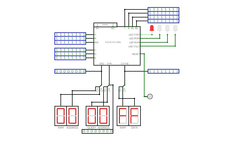
pixy
pixy is a simple 32-bit processor with twelve instructions.
pixy can...
- be easily programmed using this assembler.
- support conditional instructions.
- access between 2 and 8 MB of RAM.
here are the instructions:
- add <rn>, <rs | value>
- sub <rn>, <rs | value>
- and <rn>, <rs>
- or <rn>, <rs>
- xor <rn>, <rs>
- not <rn>
- b <value>
- mov <rn>, <rs | value>
- load <rn>, [<rs>]
- sto <rs | value>, [<rn>]
- test <rn>, <rs>
- stop
arrangement:
- top left: clock in
- middle left: data in
- bottom left: input enable
- top right: address out
- middle right: data out
- bottom right: output enable
connecting to pixy:
- pick a device you'll be using to store programs and data, i.e. RAM.
- link data in to RAM's data output through a tristate.
- link data out to RAM's data input through a tristate.
- link address out to RAM's address input.
- link clock in to an oscillator.
- link input and output enables to the tristates.
when the clock starts, the processor will try to execute any instructions found at address 0x0000.
internals:
- the CU uses microcode stored in an EEPROM to implement the instruction set.
- information is transferred between components using a data bus which is wrapped around the circuit.
- programs can access four general purpose registers and RAM. They can also talk to any peripherals connected via memory mapping.
- a FIN signal is used to mark the end of an instruction and save clock cycles.
- conditional instructions work by triggering FIN (or not) based on ALU flags.

t729 CPU - old
t729 CPU - oldt729 is a 6/12-trit balanced ternary processor.
It is built with normal binary logic gates using binary encoded ternary (10, 00, 01) to create the ternary logic gates. While this probably increases complexity, I've not found a logic simulator that does ternary. I tried circuit simulators but working with negative and positive voltages with transistors is kind of a pain and very slow to design. Sure binary encoded ternary is more wire complex but it does only require one voltage and should technically use less power and run faster. Also binary logic gates are super cheap. Using binary logic gates also means the design should work on FPGAs and could in theory get manufactured as a microprocessor.
I've gone with 6-trit = 1 Tryte for my system. 12-trit / 2 Tryte is a "word".
Data and instruction width is 6-trit (729)
Address width is 12-trit (531,441)
The t729 is a hobby project I've been extremely slowly working on for a few years.
It's purely a project for fun. Completely self taught so probably a lot of doing things the wrong way.
Currently I'm mostly hung up on instruction set. It's hard choosing which instructions to have and how to implement them.
Huge thanks to http://homepage.divms.uiowa.edu/~jones/ternary/ for the ternary logic knowledge.
If you would like to add something to the project or point something out please comment or e-mail (gmail*dyne.unlimited)
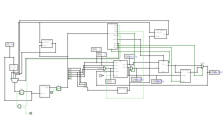
MIPS_R2000
MIPS_R2000Implementation of the processor MIPS R2000 in it's unicycle version.
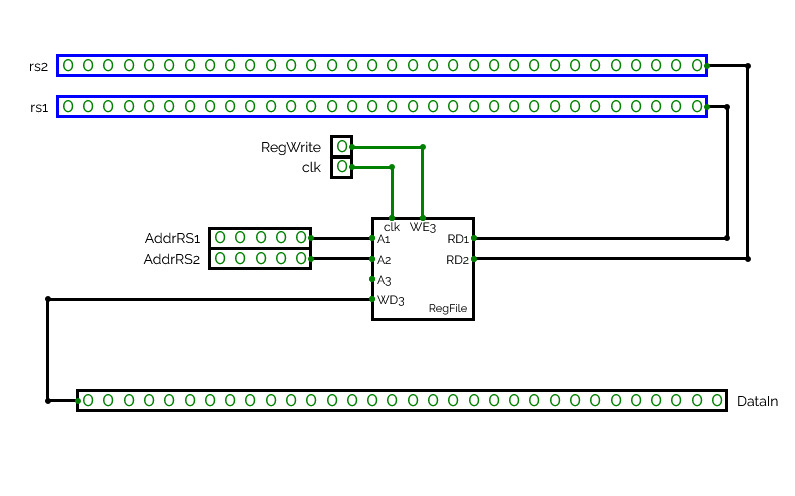

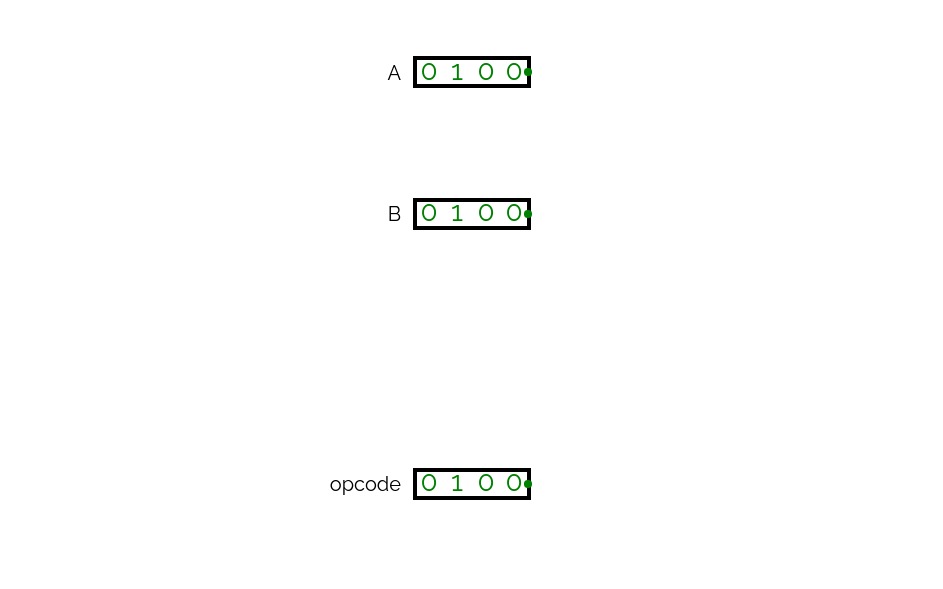
File Register for RISC-V
File Register for RISC-VThis module implemets the Register File of a basic version of RISC-V processor.
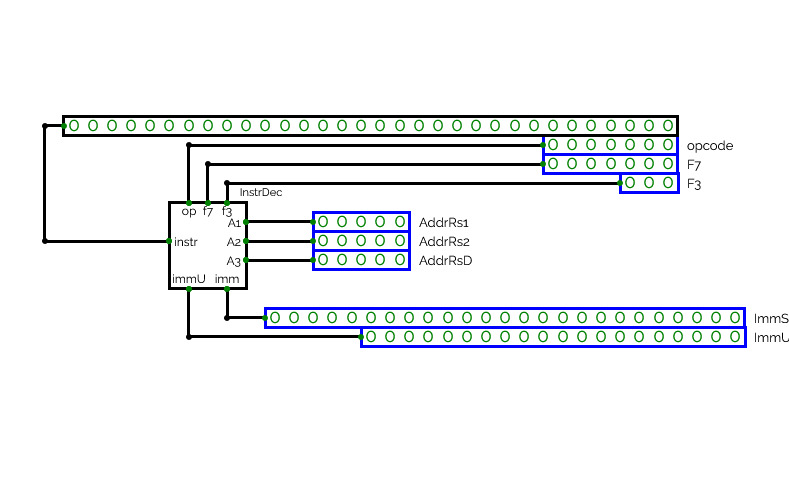
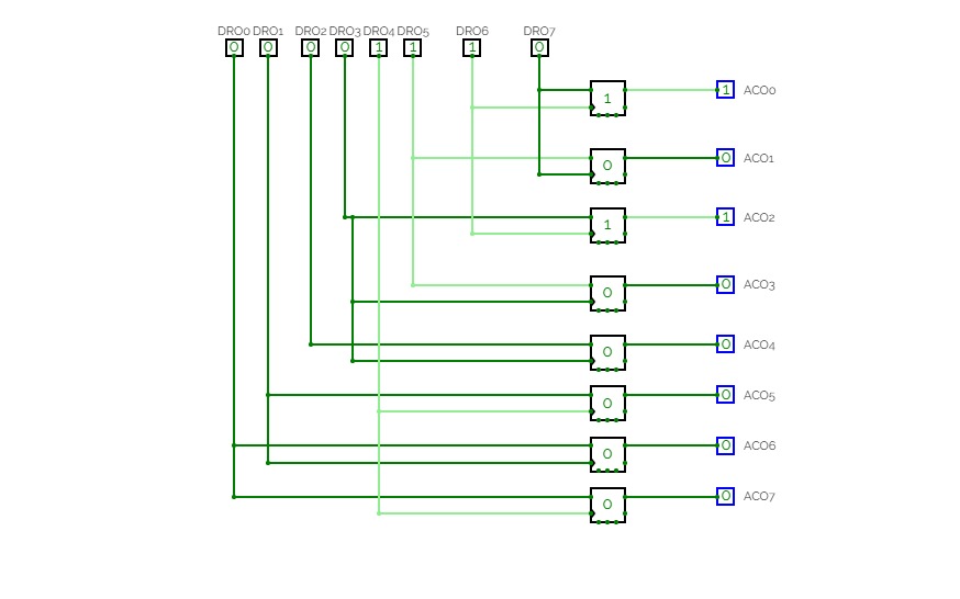
Instruction Decoder
Instruction Decoder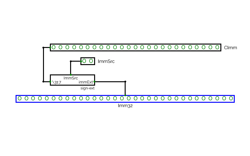
Sign Extensor
Sign Extensor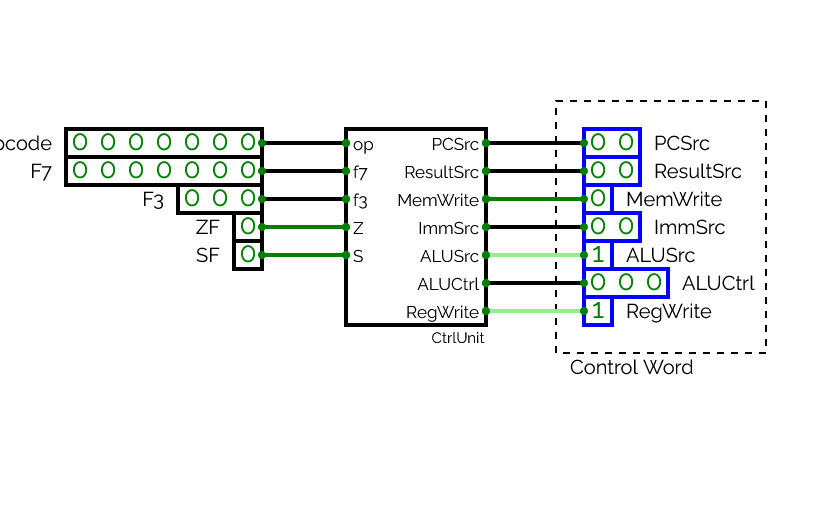
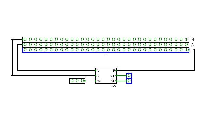
Control Unit
Control Unit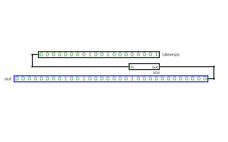
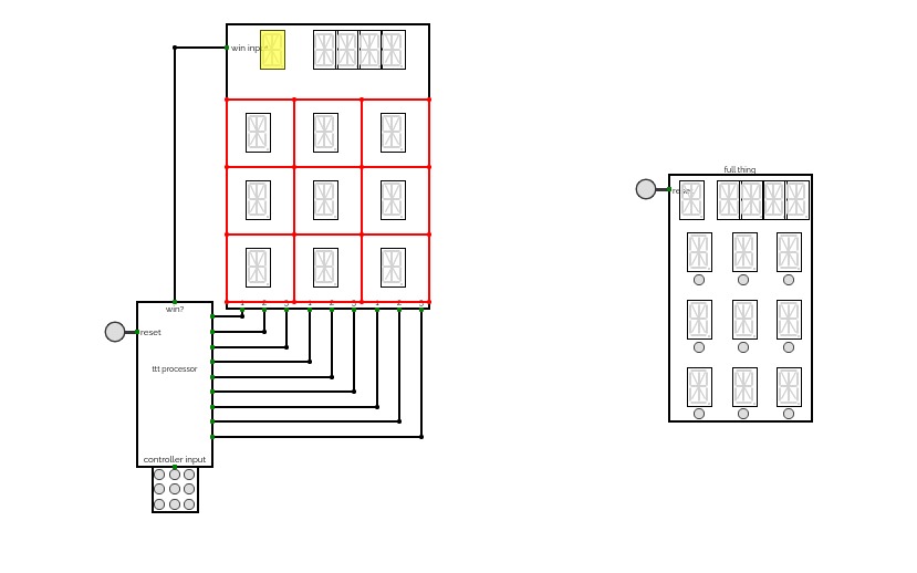
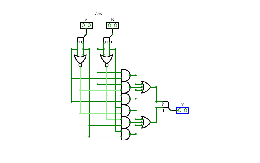
tic tac toe
tic tac toea tic tac toe circuit! press a button on the controller(the square with 9 buttons) to make a move, and the reset button to start over. X goes first, X and O switch automatically

t729 - Balanced Ternary CPU
t729 - Balanced Ternary CPUt729 is a 6/12-trit balanced ternary processor.
It is built with normal binary logic gates using binary encoded ternary (10, 00, 01) to create the ternary logic gates. While this probably increases complexity, I've not found a logic simulator that does ternary.
I've gone with 6-trit = 1 Tryte for my system. 12-trit / 2 Tryte is a "word".
Data and instruction width is 6-trit (729)
Address width is 12-trit (531,441)
The t729 is a hobby project I've been extremely slowly working on for a few years.
It's purely a project for fun. Completely self taught so probably a lot of doing things the wrong way.
Currently I'm mostly hung up on instruction set. It's hard choosing which instructions to have and how to implement them.
Huge thanks to http://homepage.divms.uiowa.edu/~jones/ternary/ for the ternary logic knowledge.
If you would like to add something to the project or point something out please comment or e-mail (gmail*dyne.unlimited)
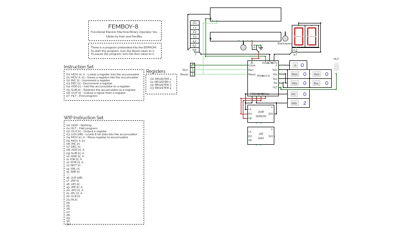

Functional Electronic Machine Binary Operator Yes - 8-bit cpu
This is a work in progress right now.
INSTRUCTION SET:
00: MOV [r], A - Loads a register into the accumulator.
01: MOV A, [r] - Saves a register into the accumulator.
02: INC [r] - Increment a register
03: DEC [r] - Decrement a register
04: ADD [r] - Add the accumulator to a register
05: SUB [r] - Subtract the accumulator to a register
06: OUT [r] - Output a signal from a register
07: HLT - End program
REGISTERS:
00: REGISTER 1
01: REGISTER 2
02: REGISTER 3
04: REGISTER 4
Update Notes:
Final design before update of is a.
To-Do:
Add WIP instructions
Add the accumulator to a register address
Increase amount of registers to 8
Add Ram manipulation instructions
Add Input to CPU
Add more operations to the ALU
Add ASCII i/o
Make a simple command line
Make an assember
Make a simple operating system for the cpu
Add rgb output


