

hiteesh
hiteesh8 Bit CPU
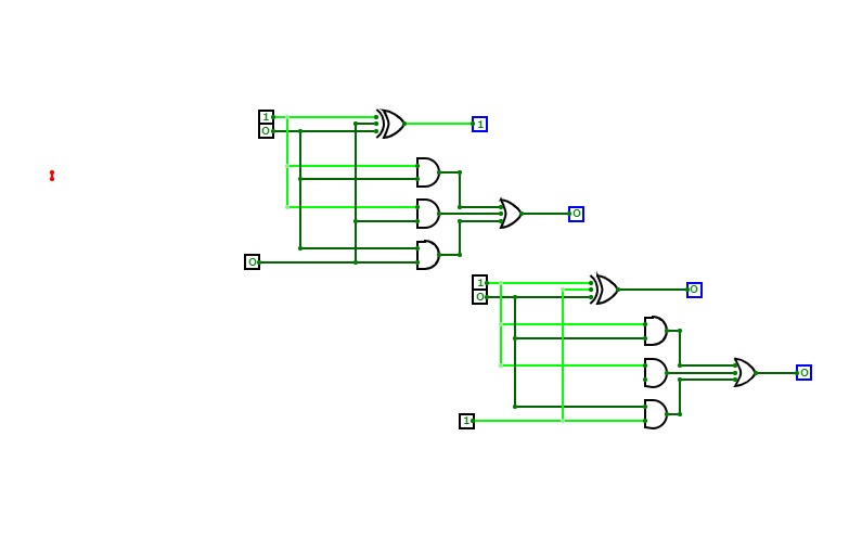
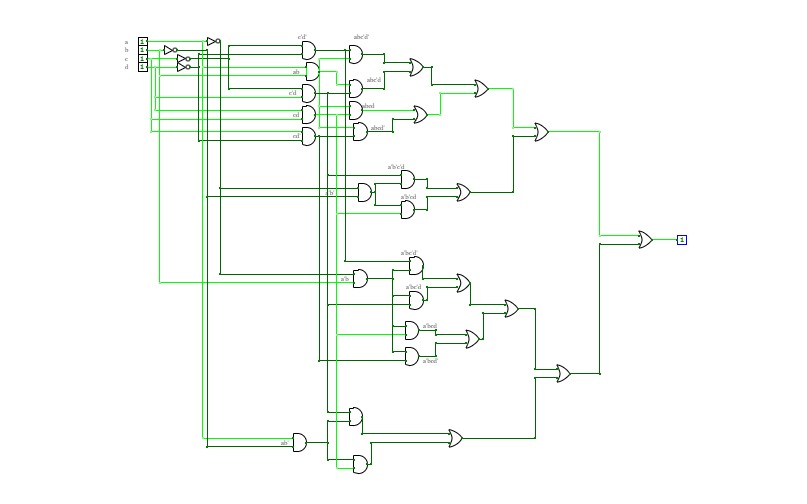
8 Bit CPUThis is a CPU witch is capable of executing a lot of stuff in one clock cycle, and this CPU can shift left up to 7 times and shift right up to 7 times witch means that it is possible to multiply and divide in one clock cycle if you program a table in the program memory. it has a 32 bit instruction width and a 8 bit address. it also has
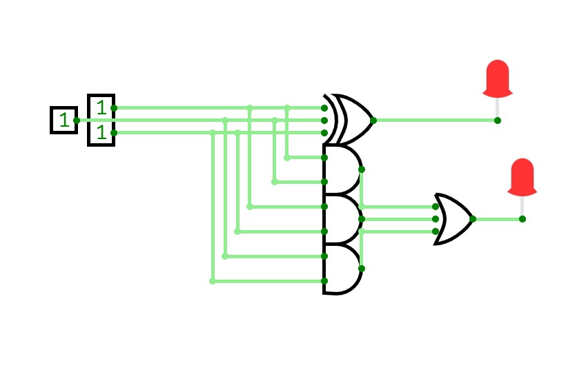
The ALU has the following operations:
- ADD
- SUBTRACT
- SHIFT_LEFT (up to 7 times per cycle 3 bit)
- SHIFT_RIGHT (up to 7 times per cycle 3 bit)
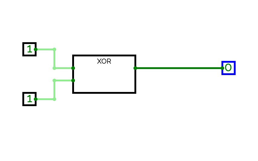
- XOR
- OR
- NOT
This Was made by miles

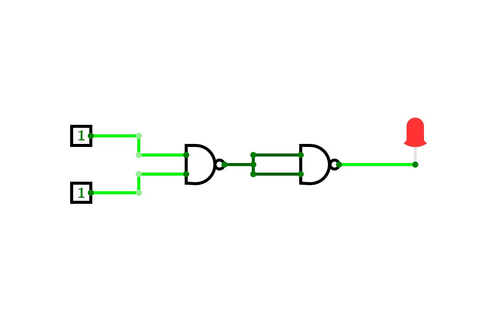
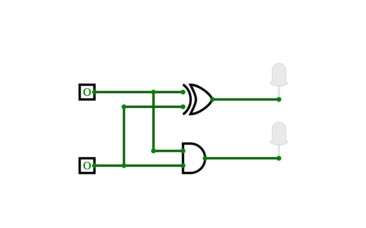
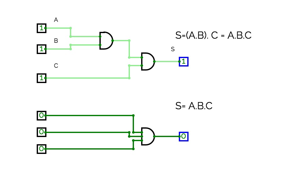
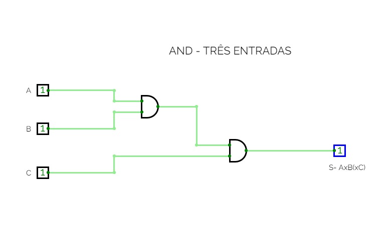
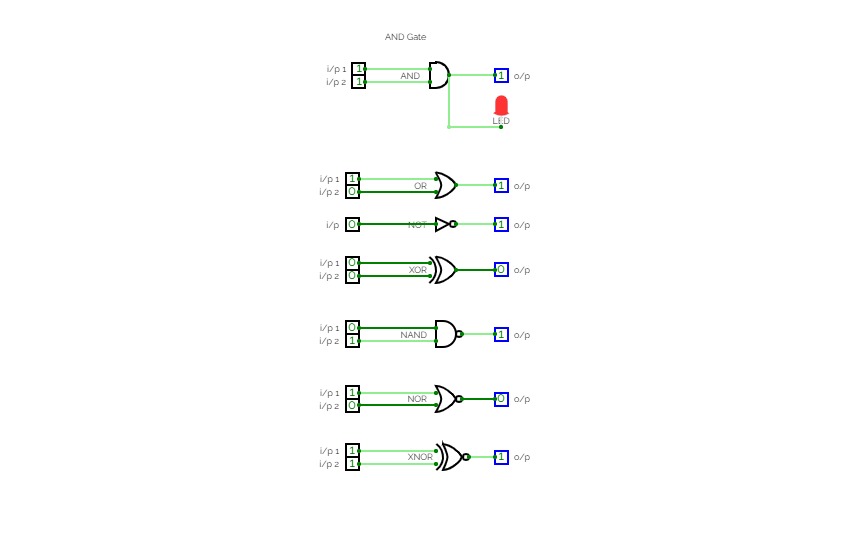
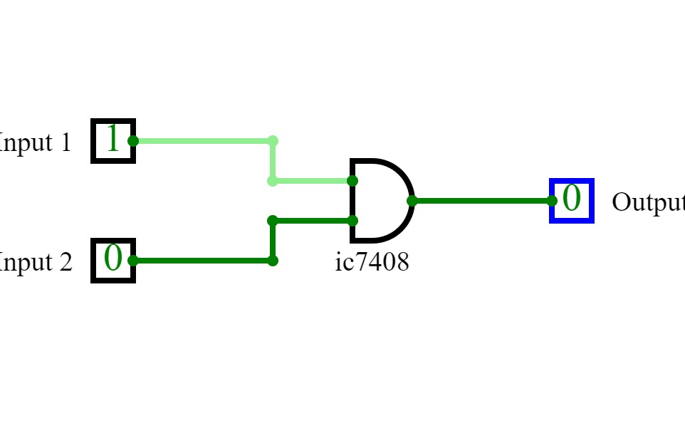
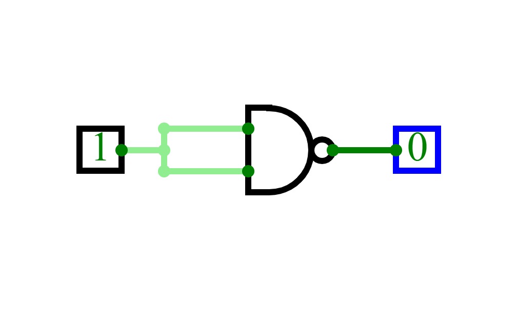
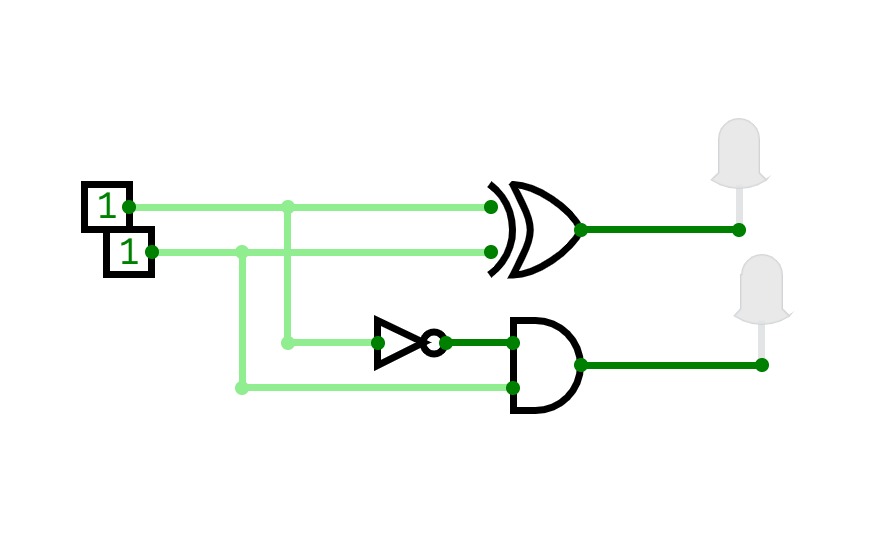
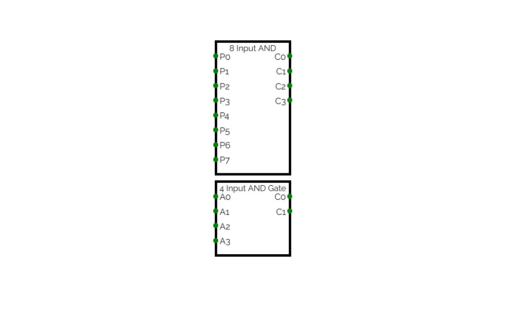
AND Gate
AND GateVariation of the Gate
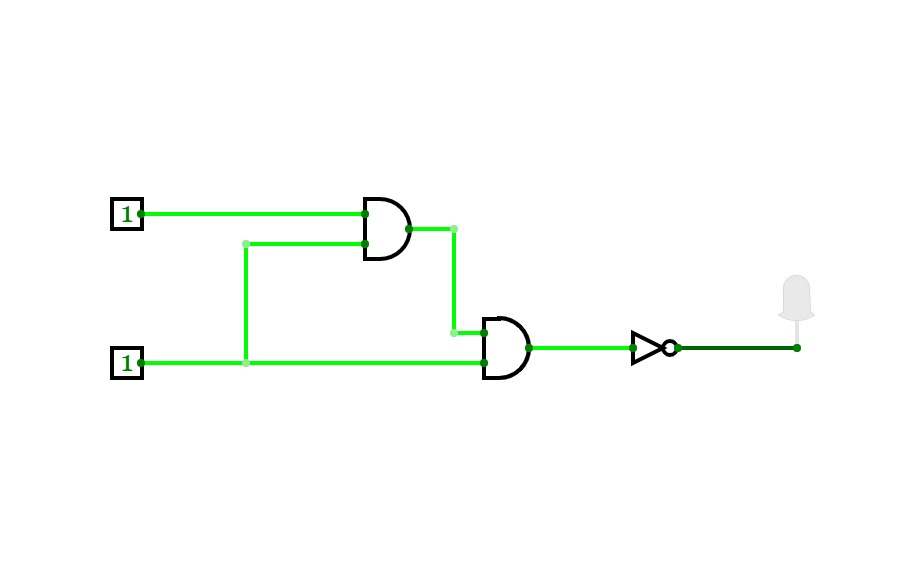
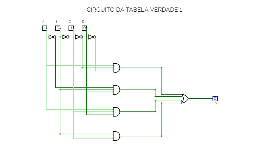
tamrin5 Q1
tamrin5 Q1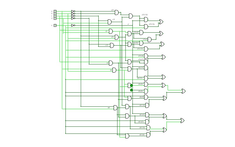
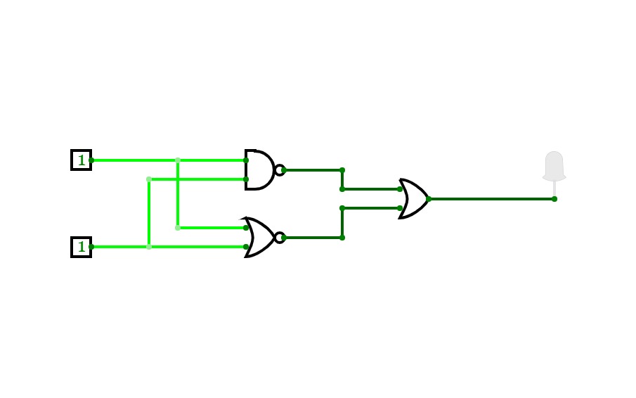
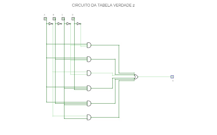
tamrin5 Q2
tamrin5 Q2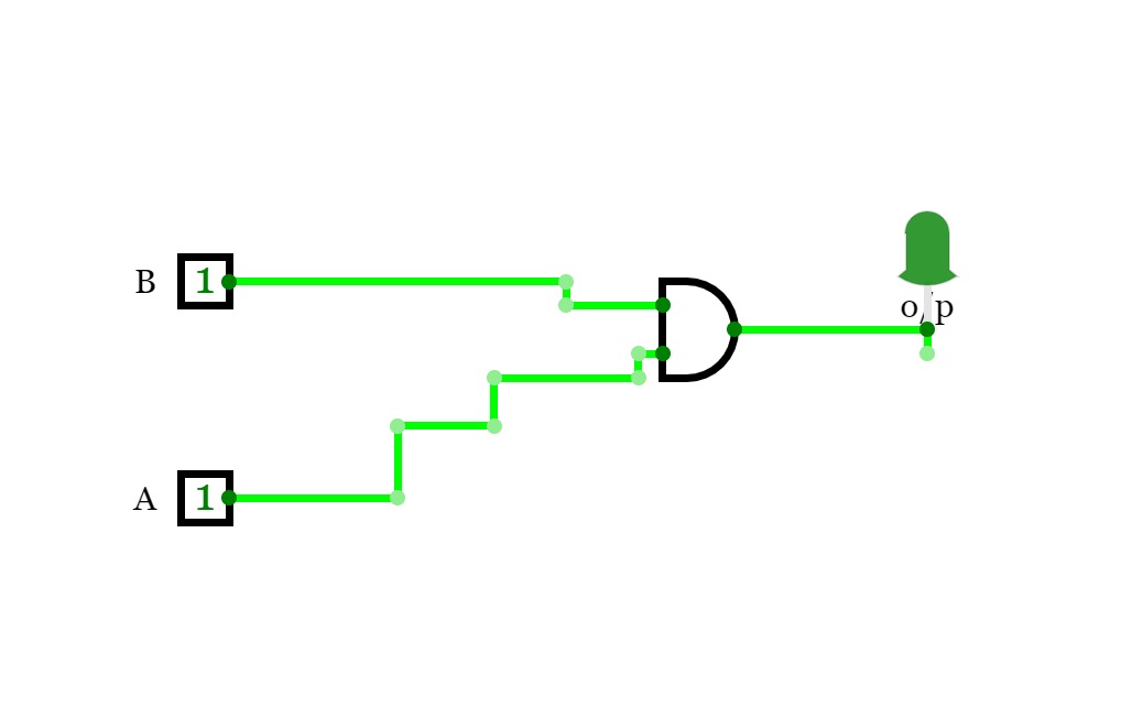
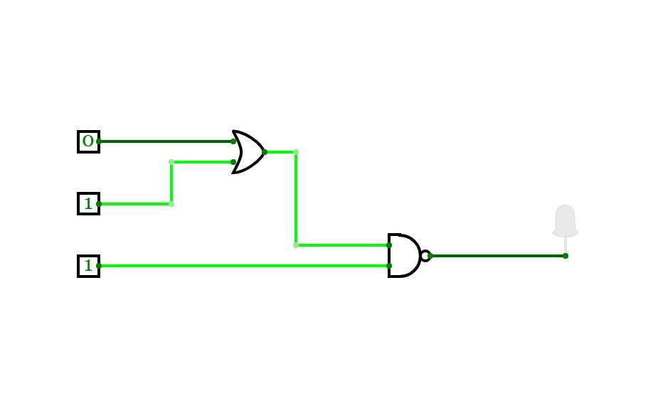
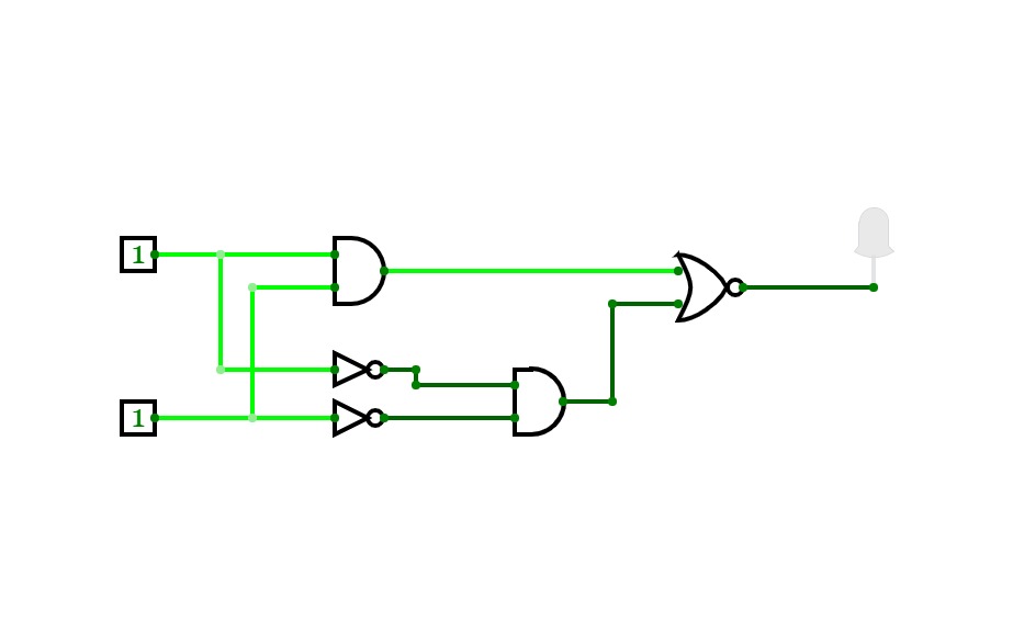
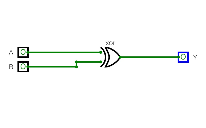
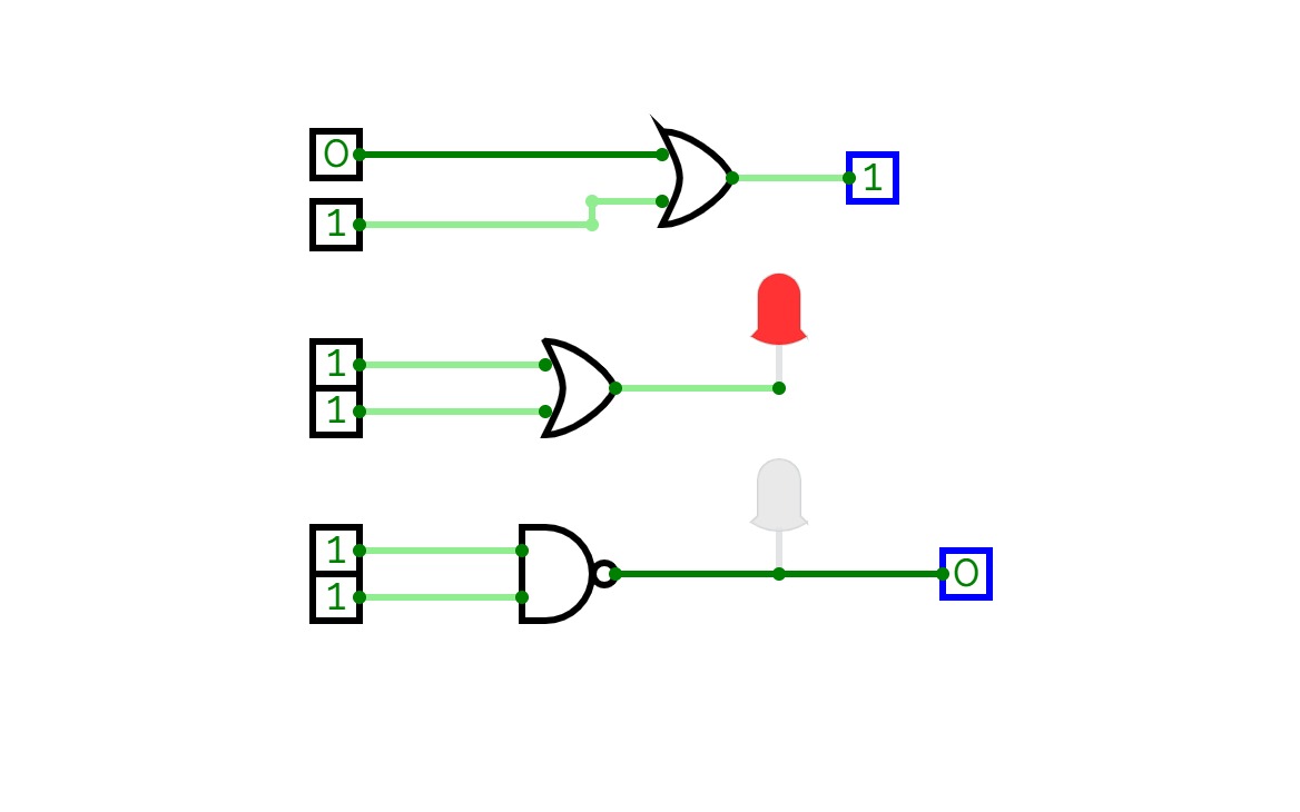
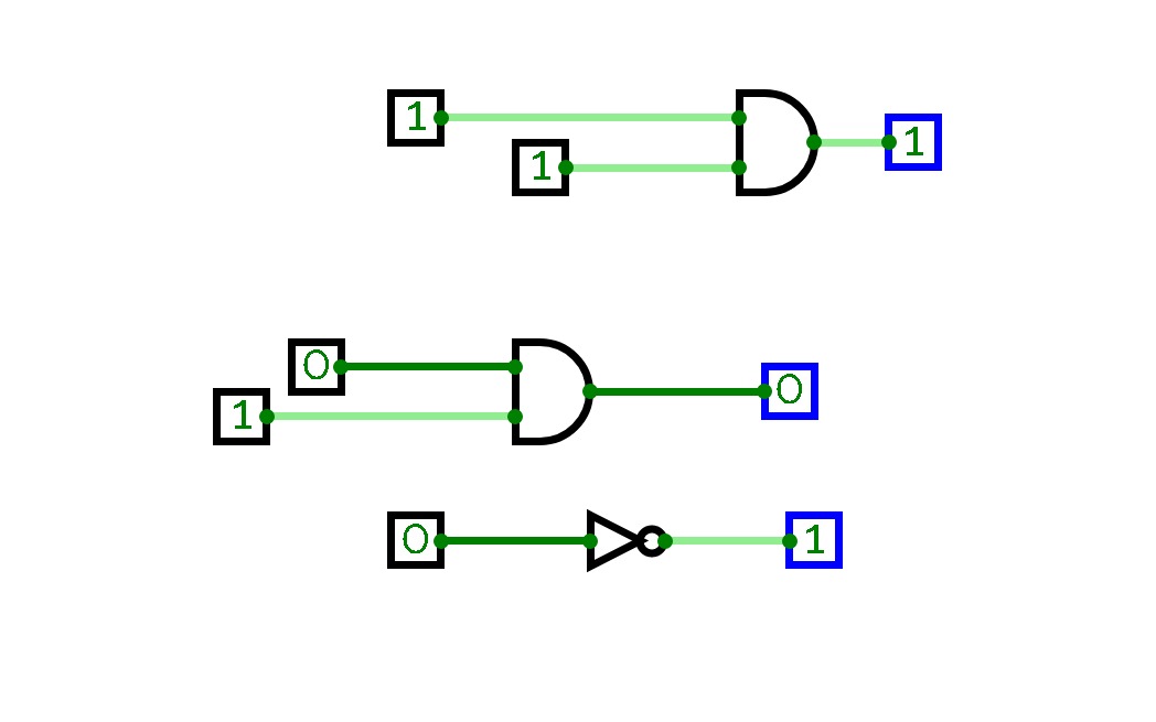
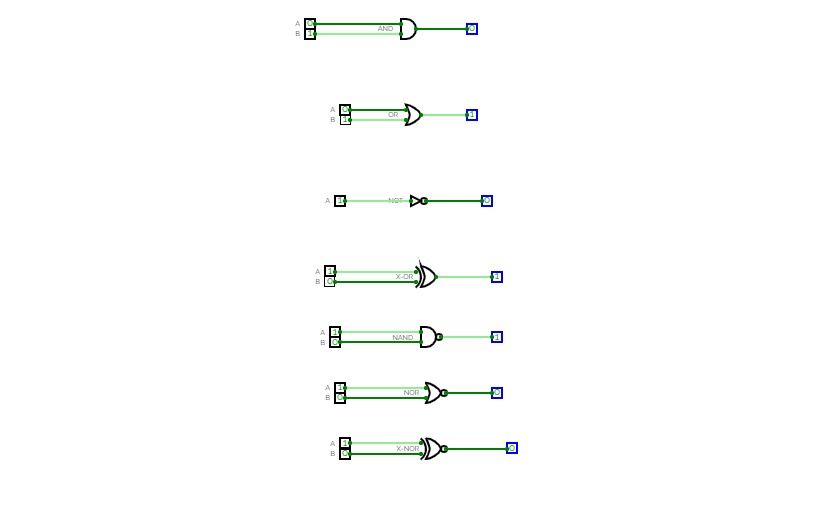
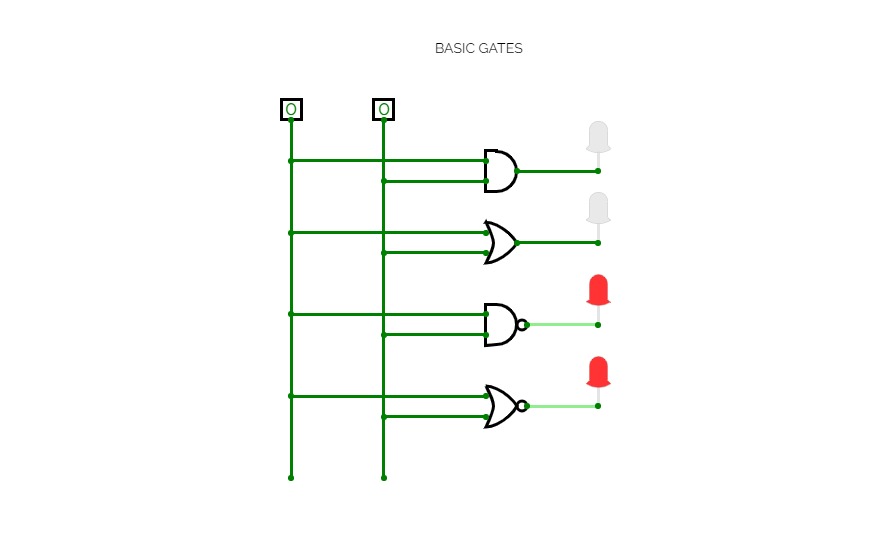
GATES
GATES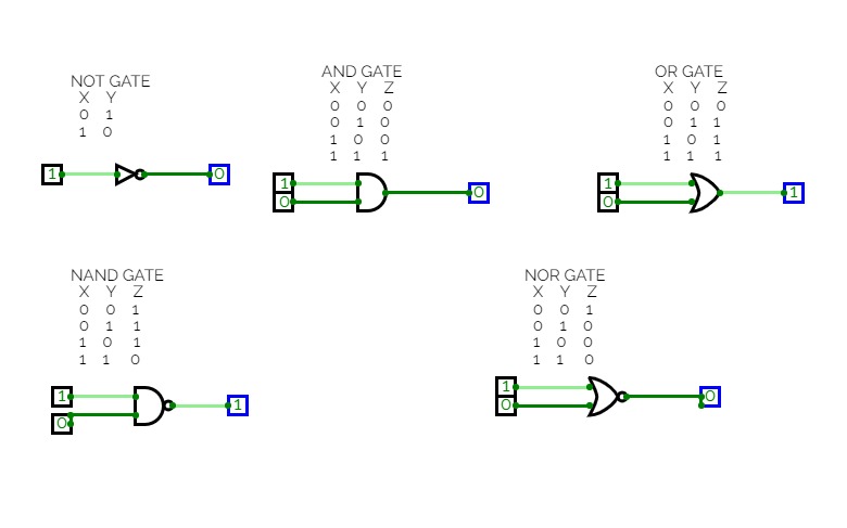
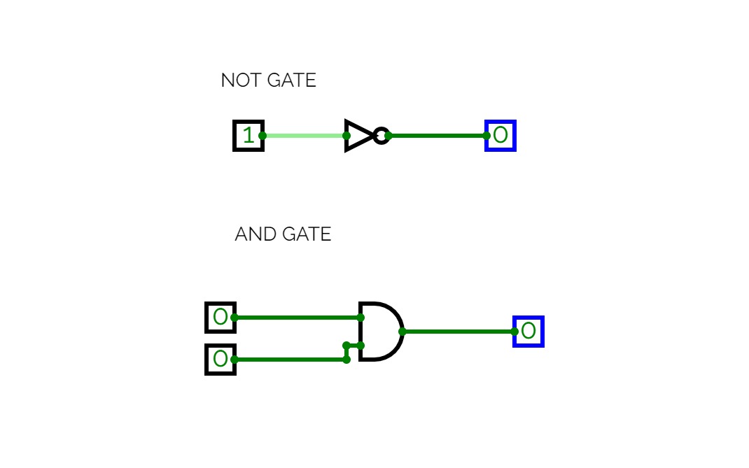
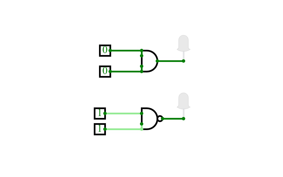
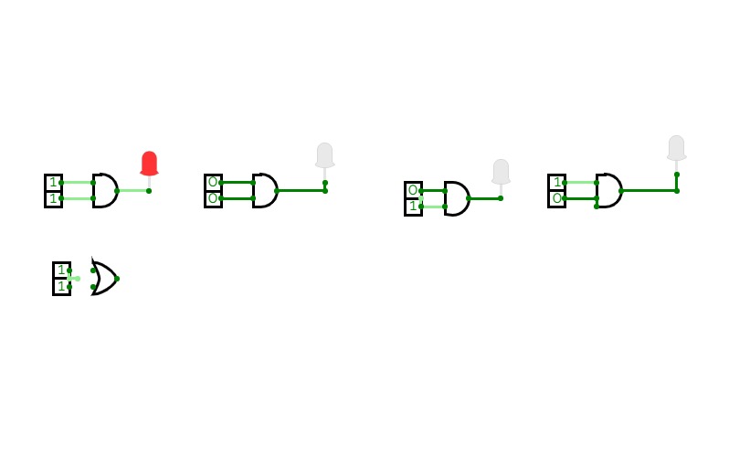
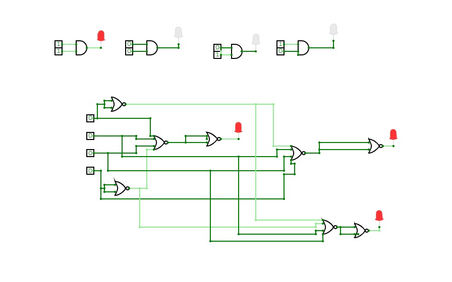

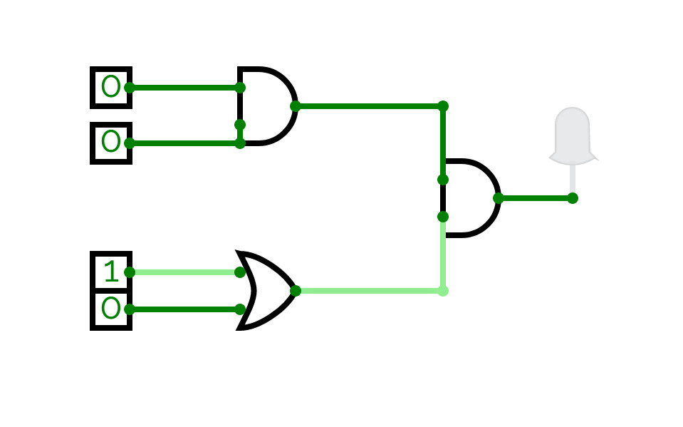
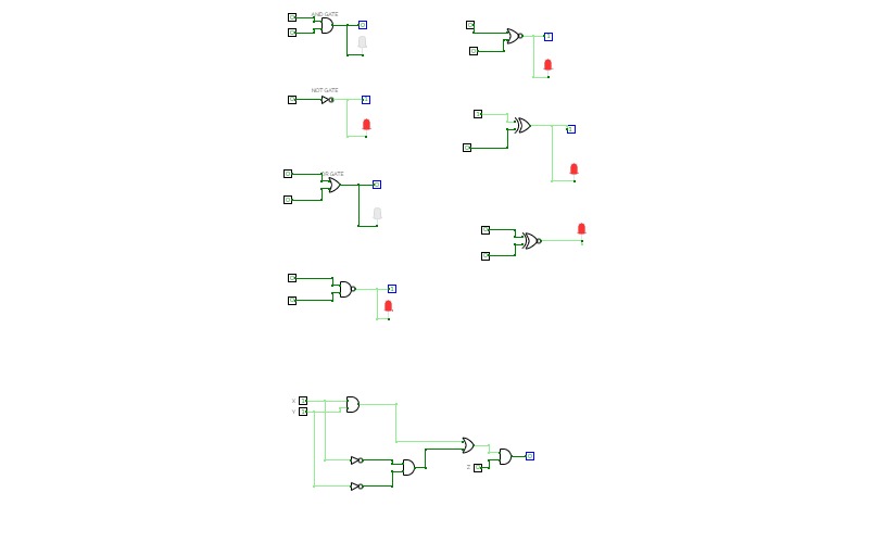
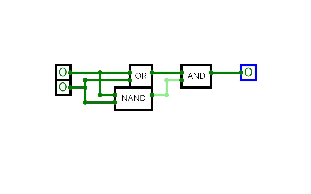
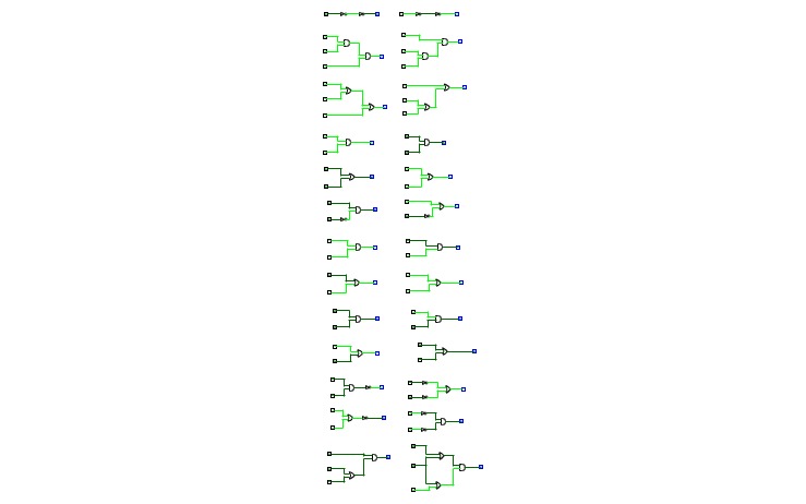
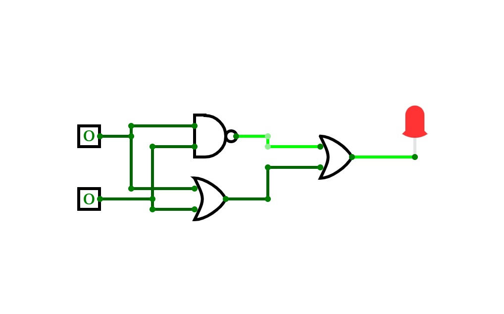
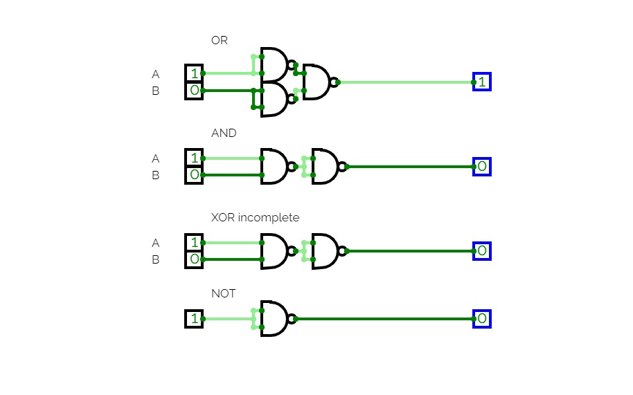
I used CircuitVerse as an alternative to the paid circuit simulator apps. One thing I love about making circuits is starting from nothing. I limited myself to using only two gates: AND and NOT. I copied this idea from the game made by Sebastian Lague. This project starts from using the built-in AND and NOT gates.
Clock
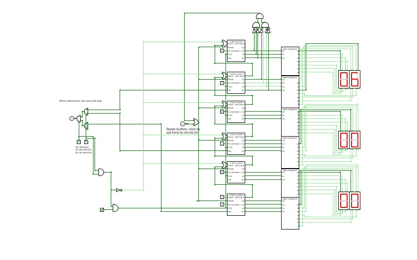
ClockThis is a simple digital clock with basic combinational and sequential logic circuits.
It can display seconds, minutes, and hours
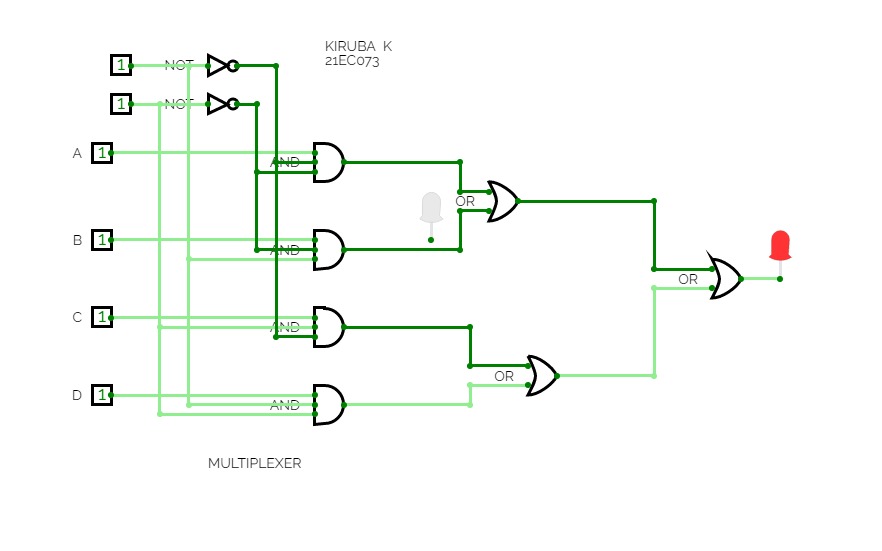
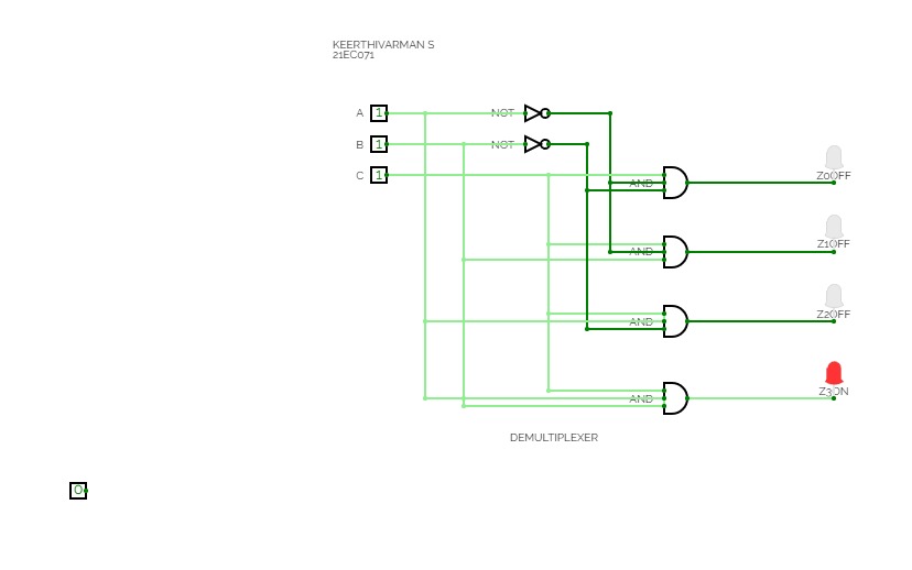
Users can set time by clicking the button and using the multiplexer to choose which to change.
Also, the design for the 4bits 7segment display and 3 bits 7segment display is inside.
Satyam Jaiswal
Satyam Jaiswalimplemented basic logic gates
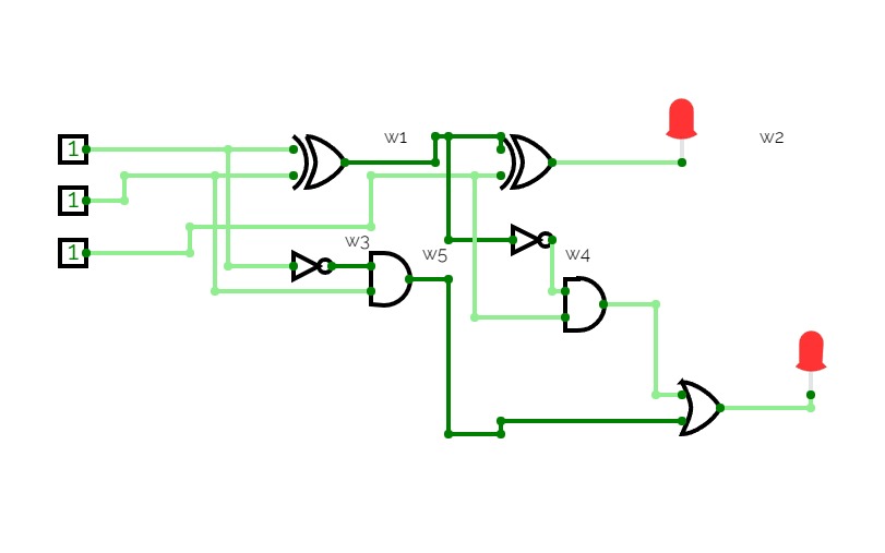
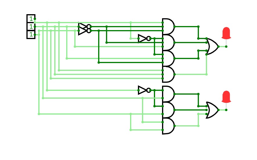
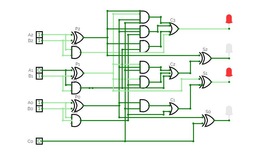
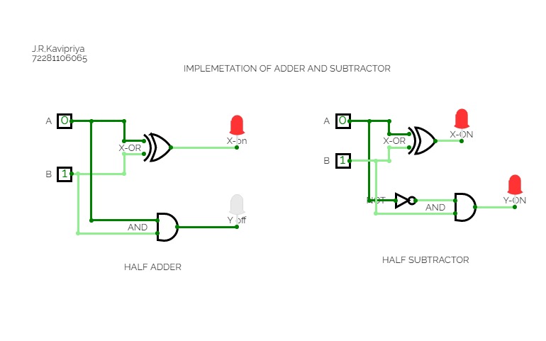
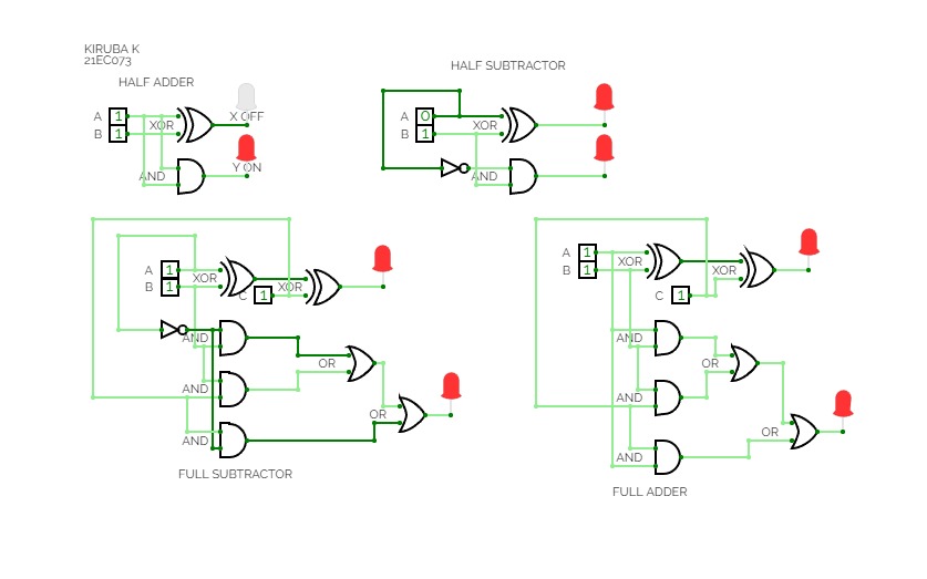
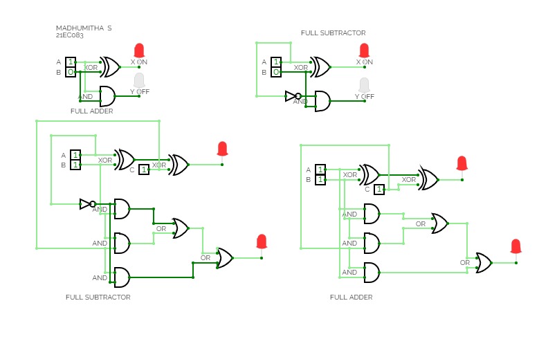
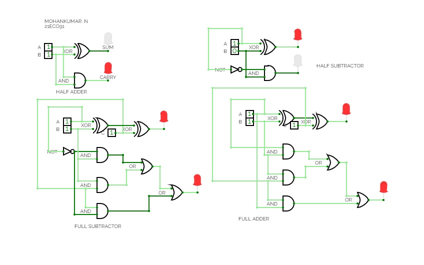
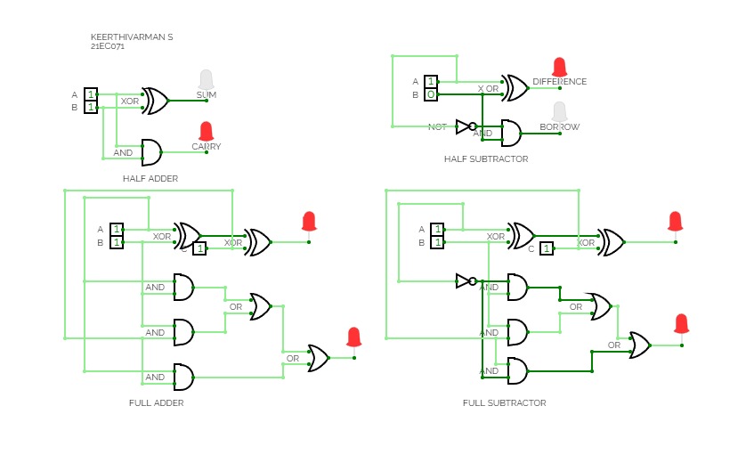
A Full Subtractor is a combinational logic circuit that is designed to perform the subtraction of two binary numbers. It is considered "full" because it not only considers the subtraction of two binary inputs but also accounts for a borrow input from the previous stage. In other words, it can subtract three binary bits - minuend, subtrahend, and borrow - to produce the difference and a borrow output.
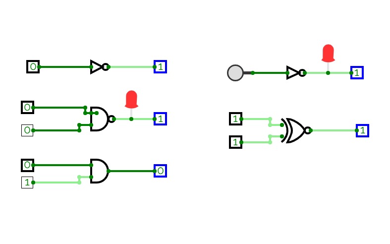


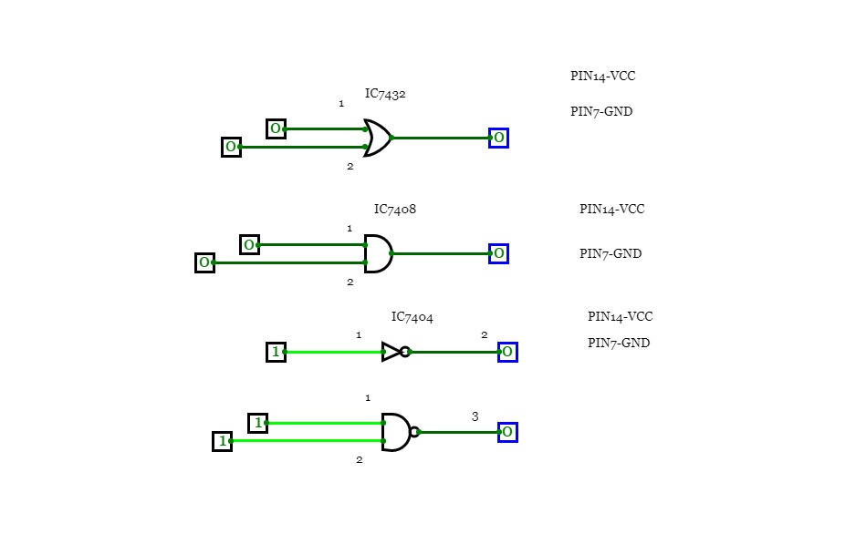
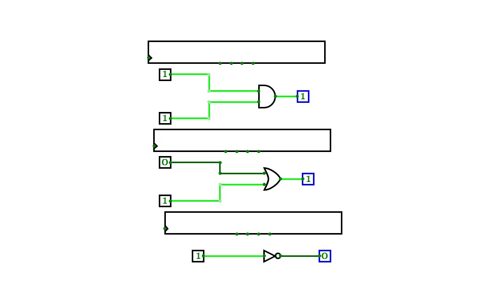
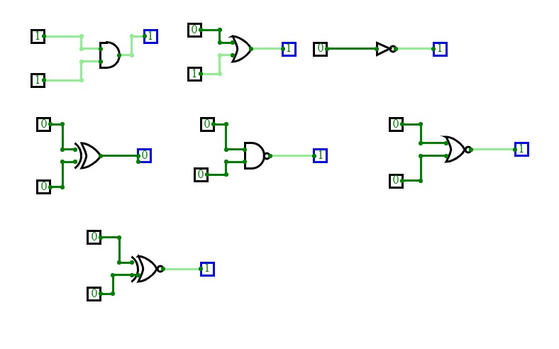
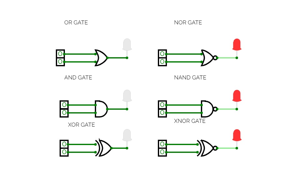
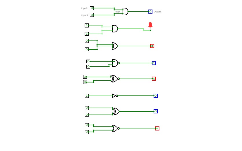
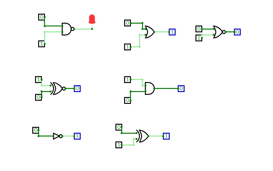
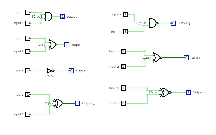
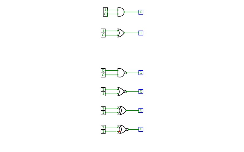
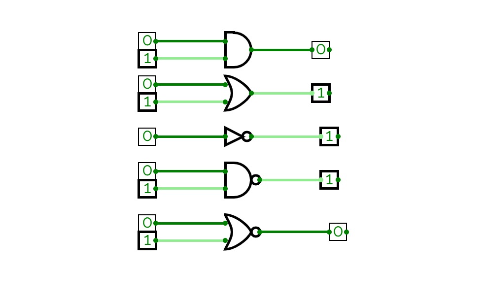
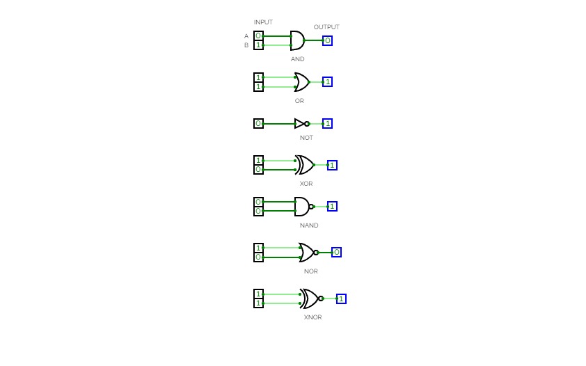
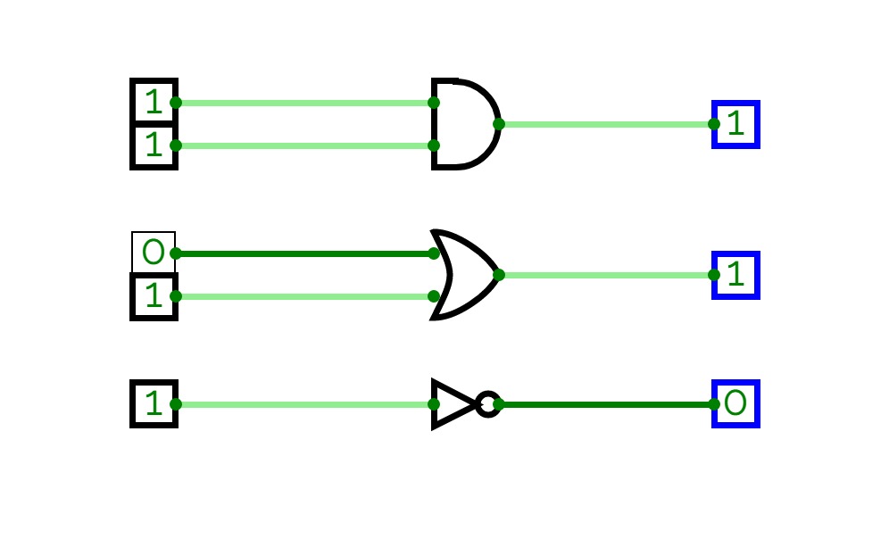
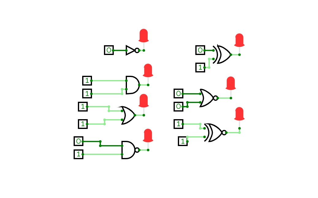
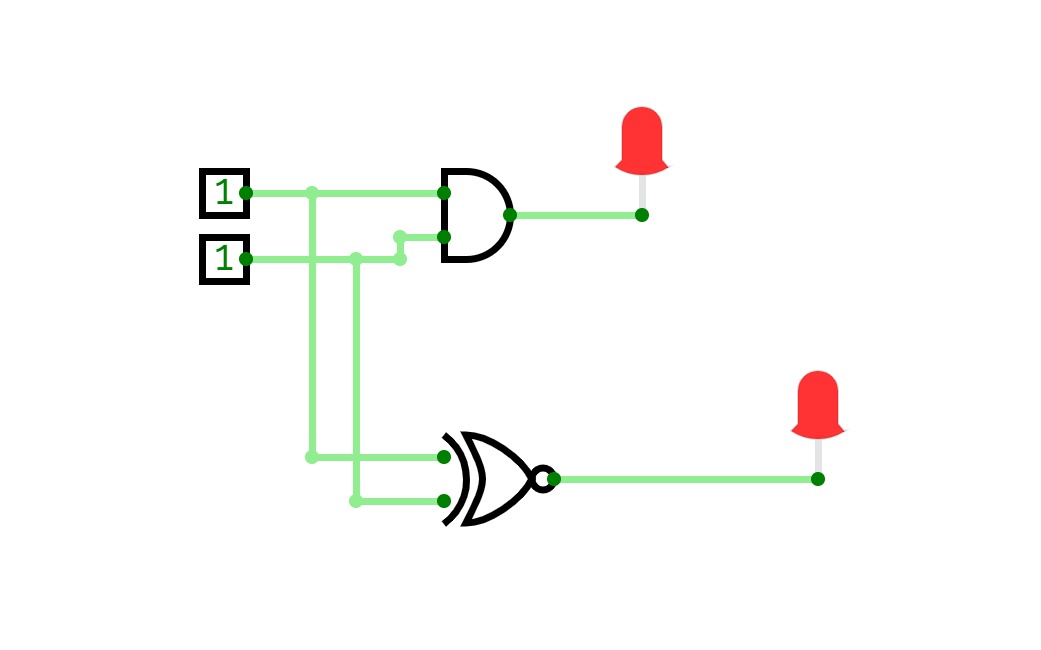
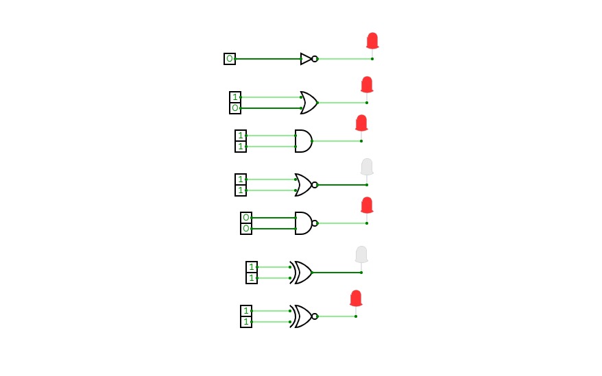
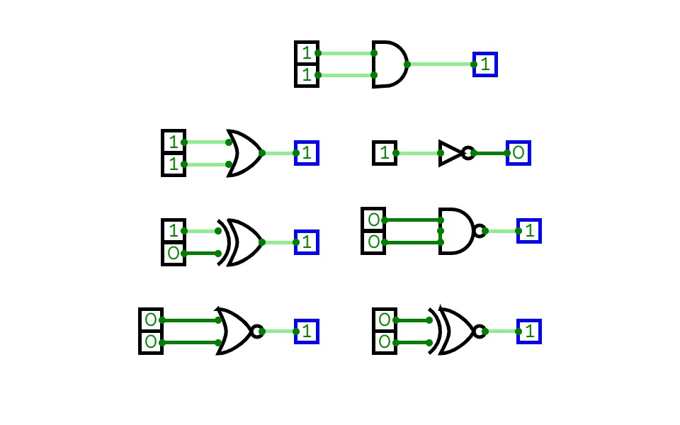
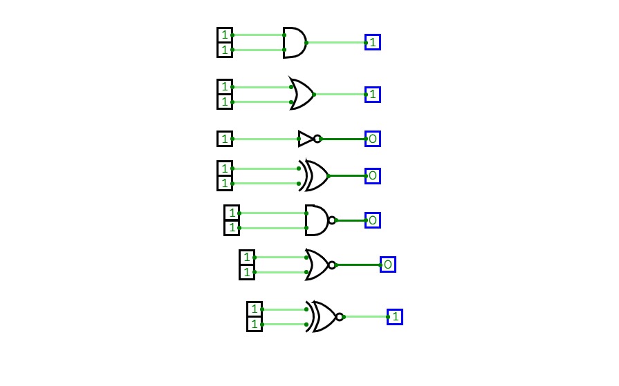
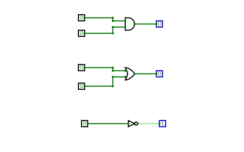
Verification of logic gates
Verification of logic gates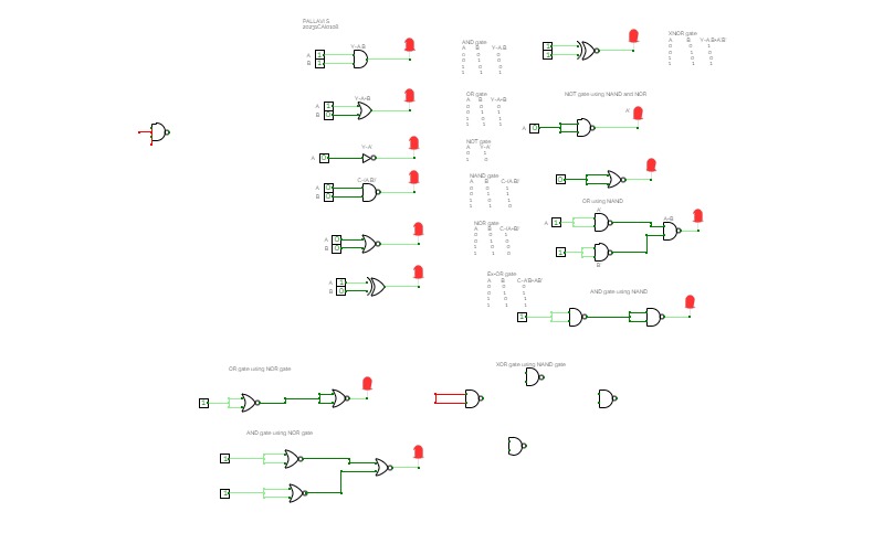
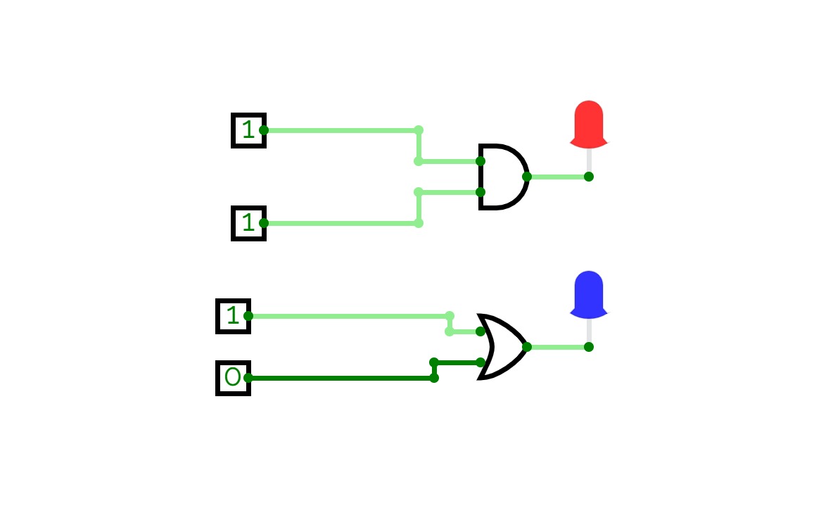
Verification of logic gates
Verification of logic gates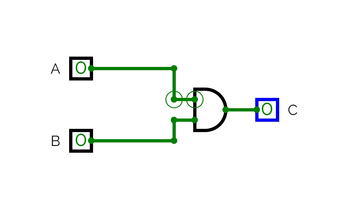


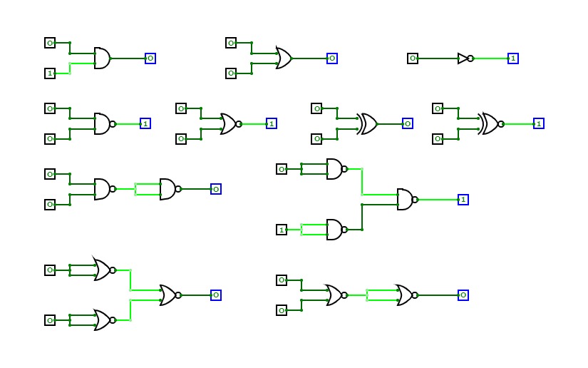
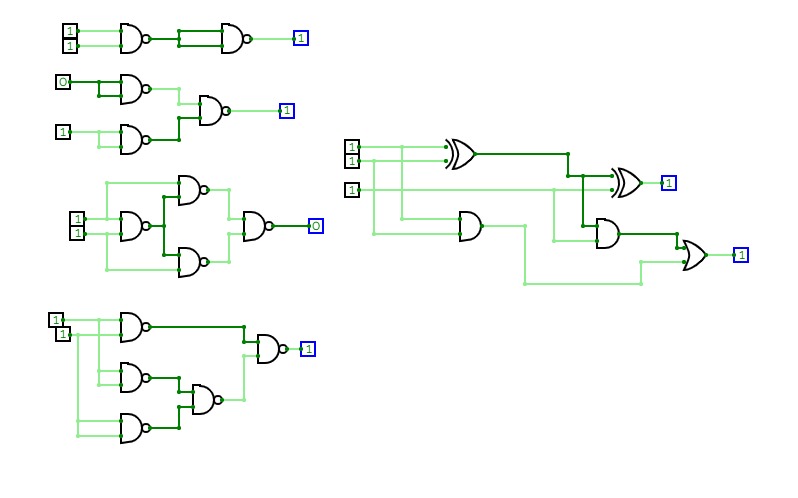
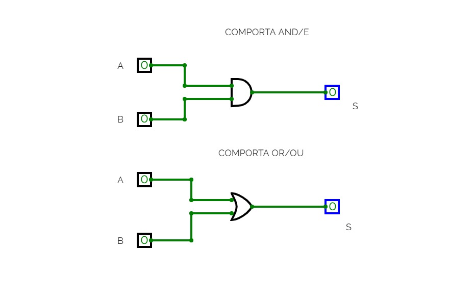
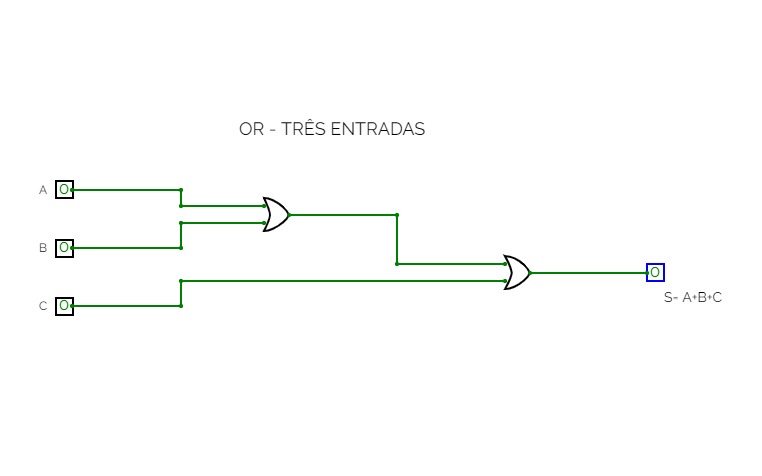
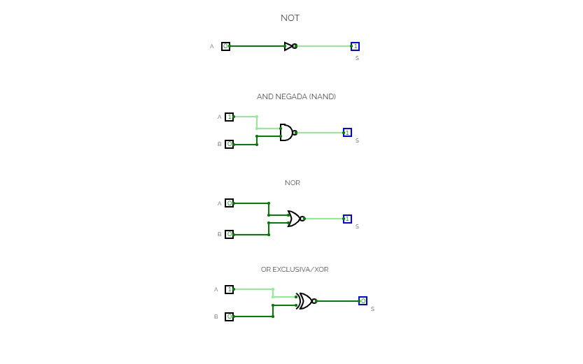
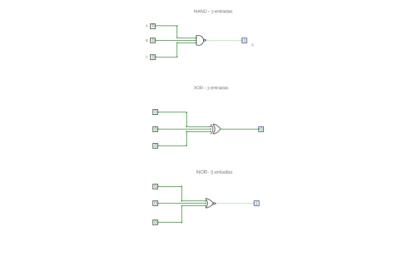
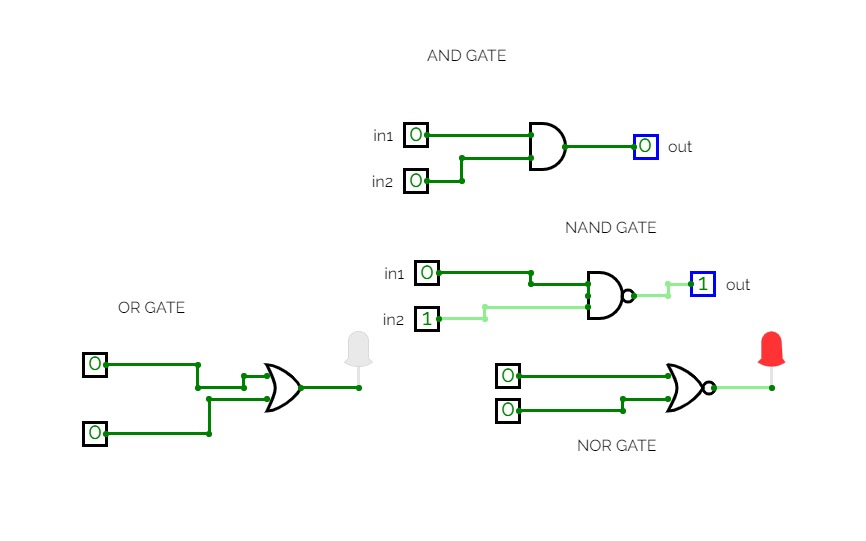
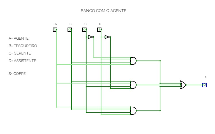
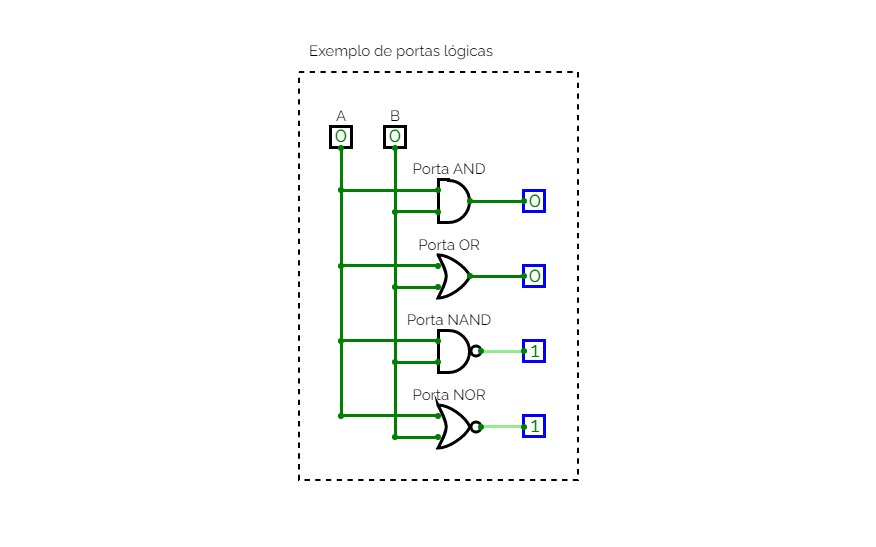
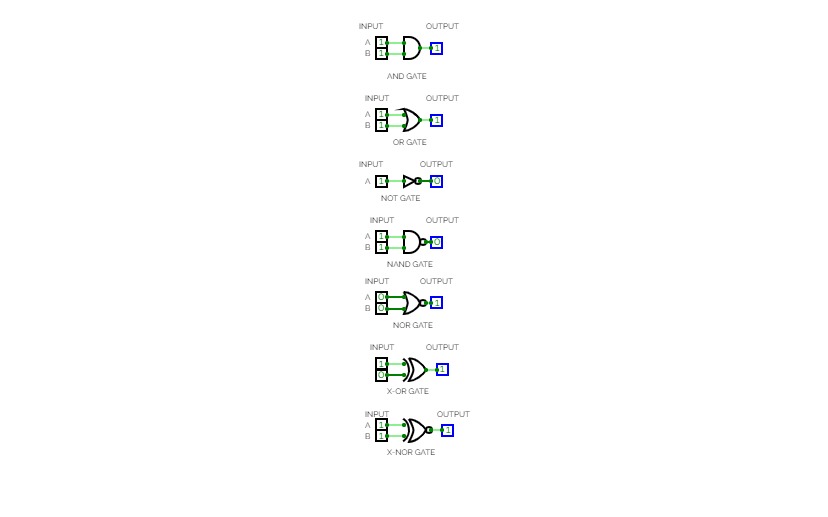
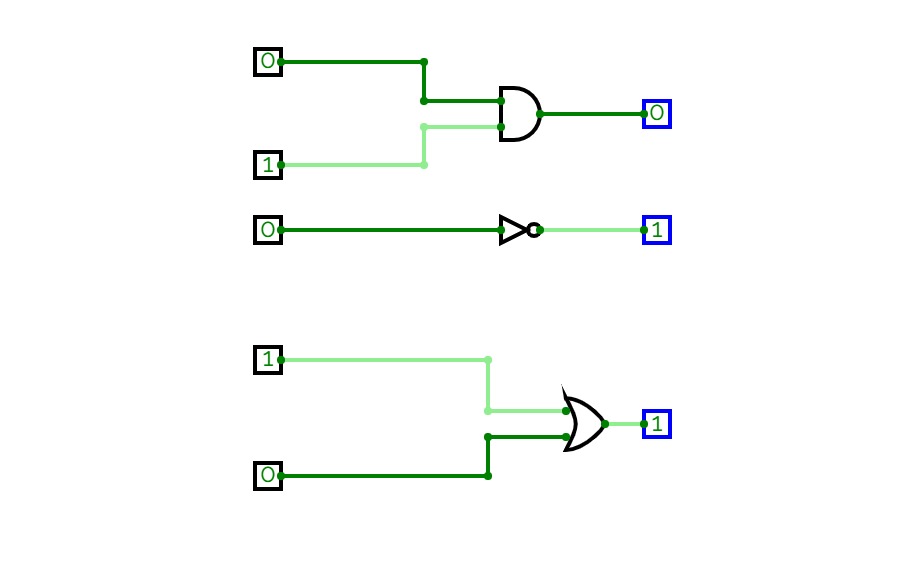
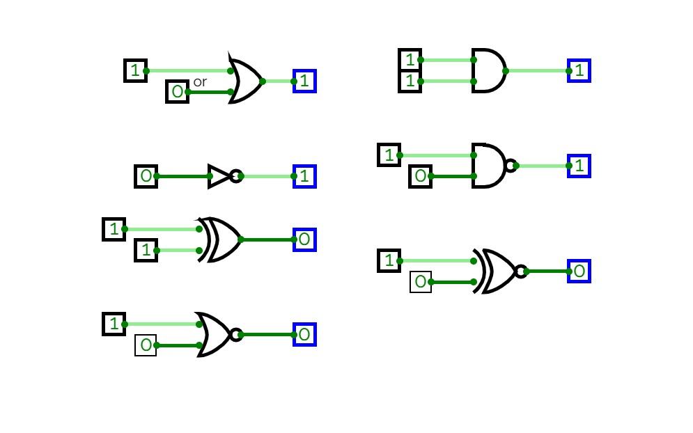
O que são Portas Lógicas?
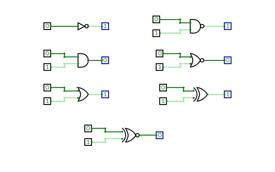
Portas lógicas são os blocos fundamentais da eletrônica digital, responsáveis pela realização das operações lógicas básicas que formam a base dos circuitos digitais. Elas recebem um ou mais sinais de entrada e produzem um sinal de saída, conforme uma lógica específica. As portas lógicas são essenciais em computadores, dispositivos eletrônicos e em diversas aplicações tecnológicas, pois são usadas para executar operações como soma, subtração, comparação, e outras funções lógicas necessárias para o funcionamento de sistemas digitais.
Cada porta lógica tem uma função definida e pode ser representada por um símbolo específico em diagramas elétricos. As operações realizadas por essas portas são baseadas nas leis da lógica matemática, particularmente na álgebra booleana, que permite a manipulação de variáveis binárias (0 e 1).


