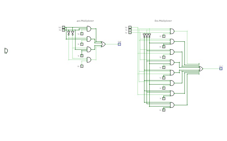
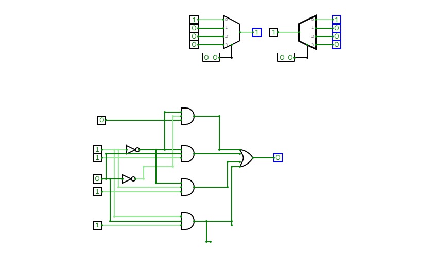
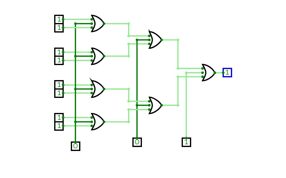
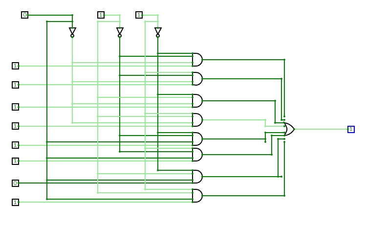
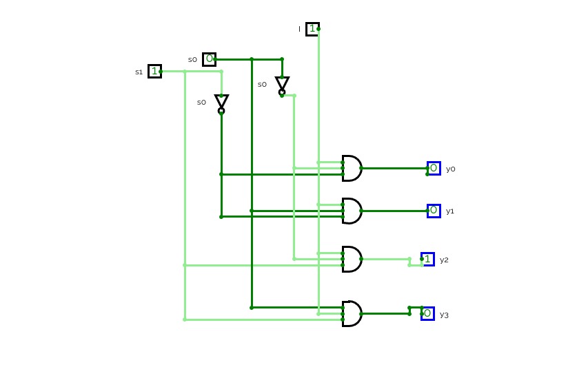
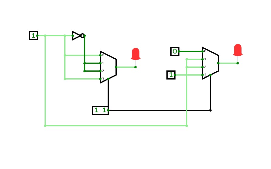
4:1+4:1+2:1=8:1
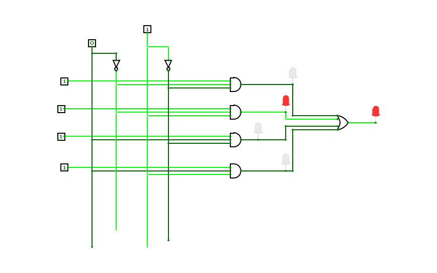
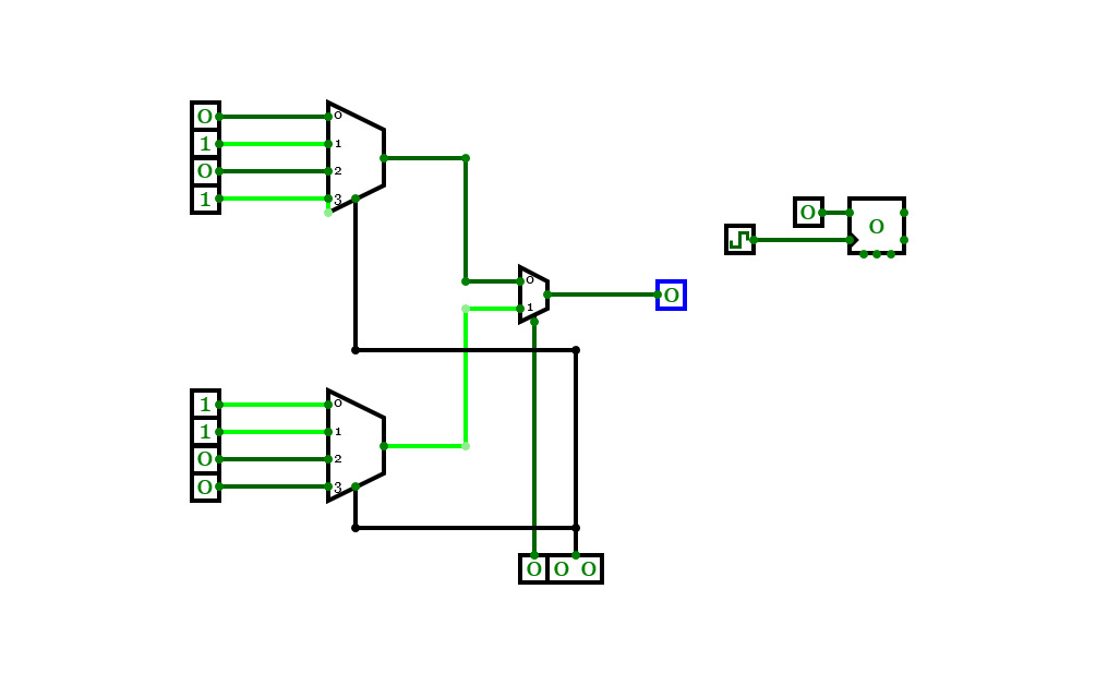
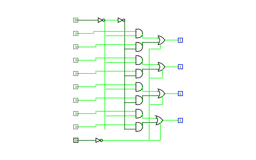
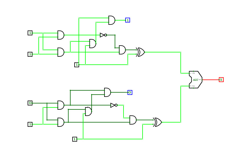
4:1+4:1+2:1=8:1Basic Multiplexer
Basic MultiplexerMUX
MUXMultiplexer
MultiplexerMultiplexers
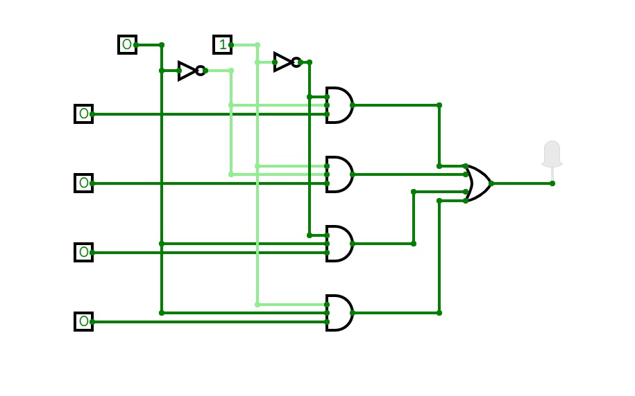
MUX - Zadatak 3 (za ocjenu 2)
MUX - Zadatak 3 (za ocjenu 2)MUX - Zadatak 3 (za ocjenu 3)
MUX - Zadatak 3 (za ocjenu 3)MUX - Zadatak 3 (za ocjenu 4)
MUX - Zadatak 3 (za ocjenu 4)MUX - Zadatak 3 (za ocjenu 5)
MUX - Zadatak 3 (za ocjenu 5)MUX
MUXMUX
MUXMUX
MUXMUX - 2019./20.
MUX - 2019./20.multiplexer
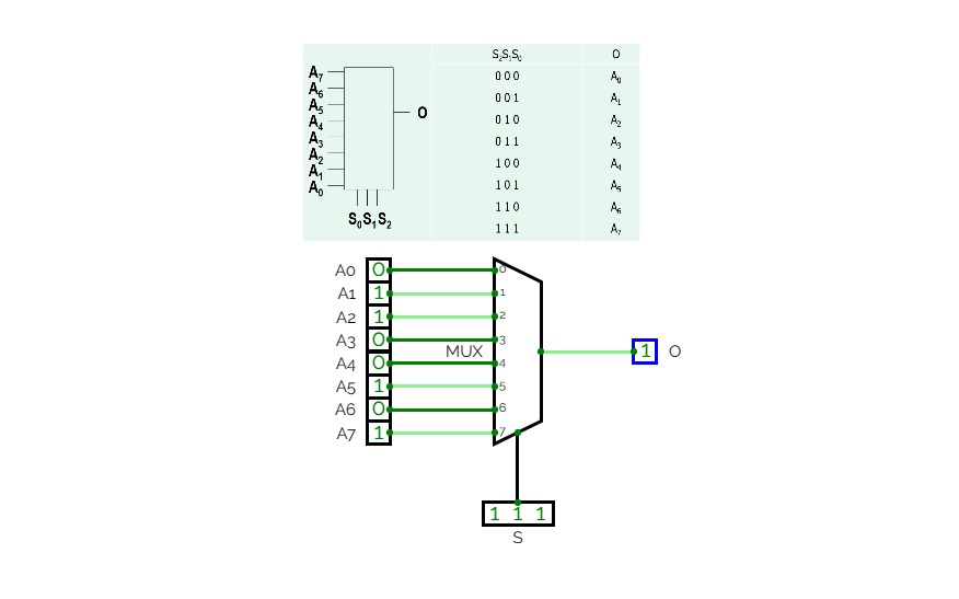
multiplexerMultiplexer: 2:1 MUX, 4:1 MUX, 8:1 MUX
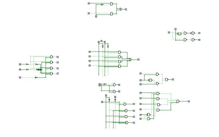
Implementation of functions and gates with MUX
8 to 1 multiplexer
8 to 1 multiplexer4 to 1 multiplexer
4 to 1 multiplexer38
38Kaivalya 21444 implementation of 8:1 MUX using two 4:1 MUX
Kaivalya 21444 implementation of 8:1 MUX using two 4:1 MUXMultiplexer 8 a 4
Multiplexer 8 a 4multiplexer8:1
Multiplexer_1
Multiplexer_1ALU multiplexer
ALU multiplexerMULTIPLEXER ALU
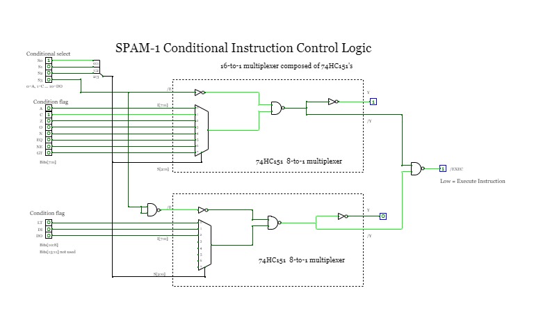
spam 1 conditional instruction logic
spam 1 conditional instruction logicComposes a 16-to-1 multiplexer using 74151/74HC151/74HCT151 for the purpose of creating an active low signal when the selected status condition flag is also low.
See also project resources:
- https://github.com/Johnlon/spam-1
- https://hackaday.io/project/166922-spam-1-8-bit-cpu
- https://www.youtube.com/channel/UCG6rvUou0GMLyTbjs4Ro2zg
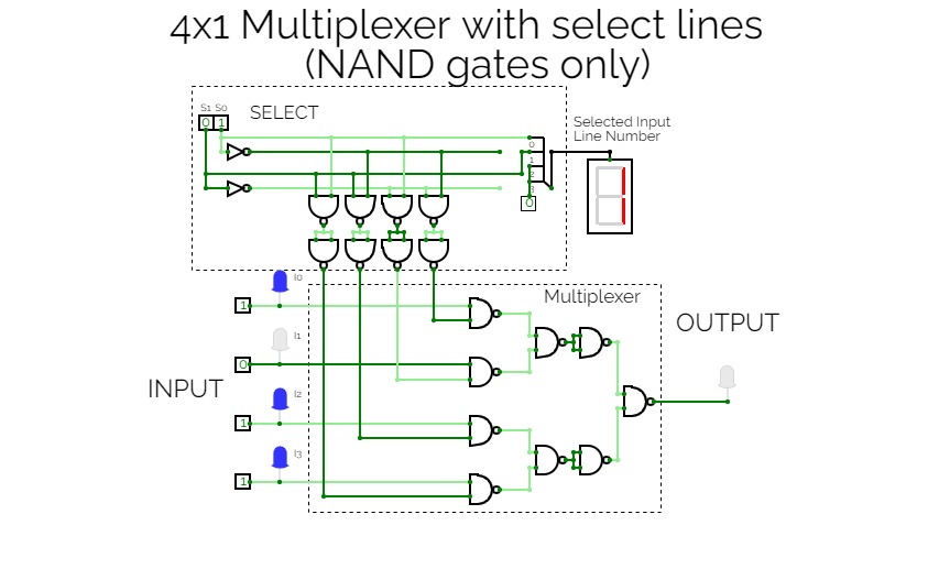
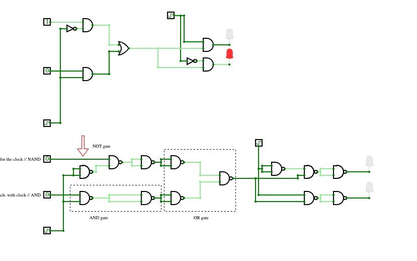
Multiplexer with NAND only
Multiplexer with NAND onlymultiplexer
multiplexerShubhranshu Yadav
Shubhranshu Yadavexperiment 2 DEMUX+questions
experiment 2 DEMUX+questionscombination-circuit
combination-circuitqstn2--D/19/EE/018
qstn2--D/19/EE/018Riki Tantowi
Riki Tantowi8x1 Multiplexer
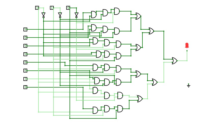
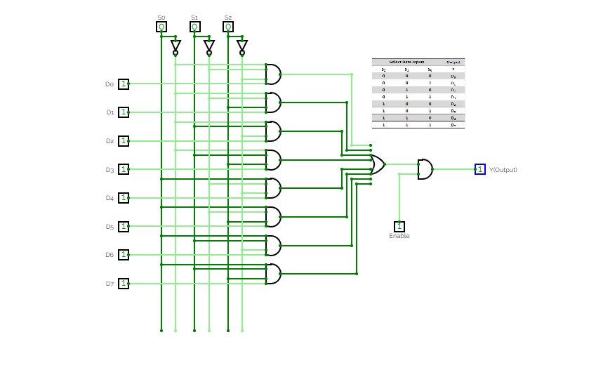
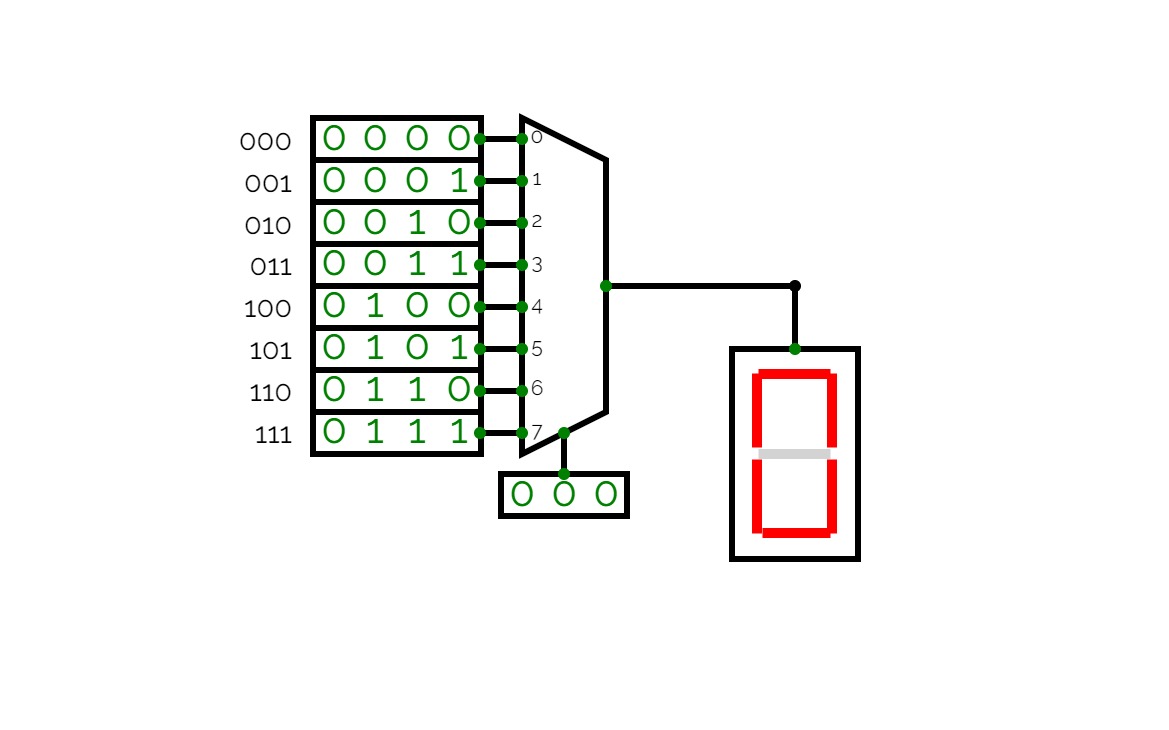
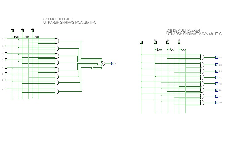
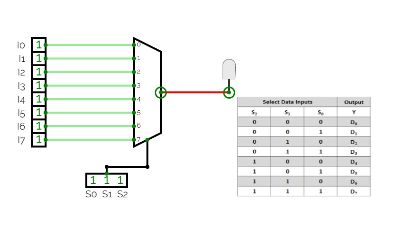
8x1 Multiplexer8x1 multiplexer has 8 data input lines I0, I1, I2, I3, I4, I5, I6, I7, 3 select lines S0, S1, S2 and one output, Y.
Truth Table for 8x1 Multiplexer
Data Select Input
Output
Y
S2
S1
S0
0
0
0
I0
0
0
1
I1
0
1
0
I2
0
1
1
I3
1
0
0
I4
1
0
1
I5
1
1
0
I6
1
1
1
I7
Final - Multiplexer
Final - MultiplexerFirst multiplexer following tutorial with switched outputs, second multiplexer with universal logic gates (only NAND)
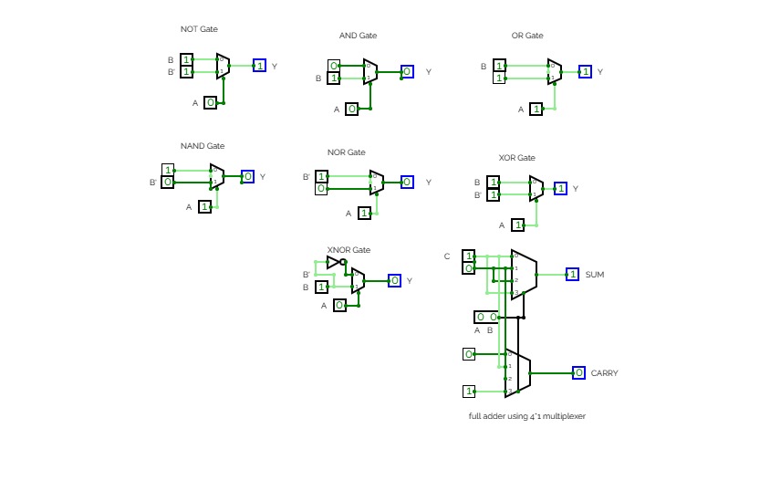
full adder using mux
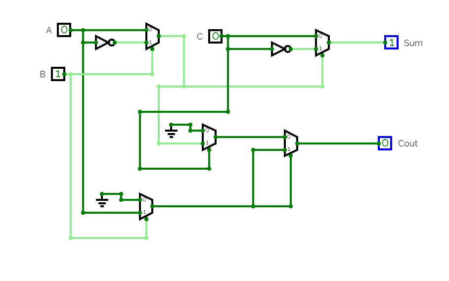
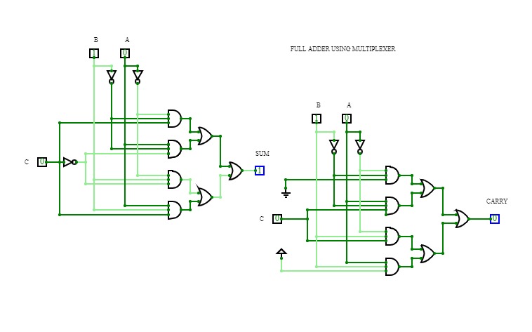
full adder using muxIt is a full adder circuit made using multiplexer from basic gates.
Multiplexer
MultiplexerDesign multiplexer using basic gates,
Boolean function implementation
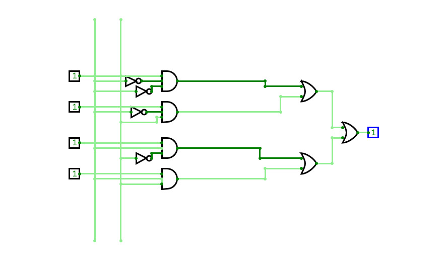
4x1 MUX
4x1 MUX4x1 and 8x1 MUX
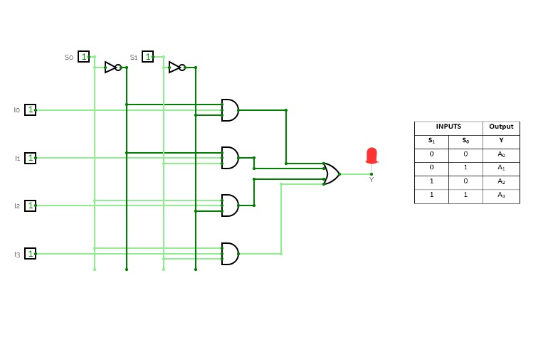
4x1 and 8x1 MUX4 to 1 MUX
4 to 1 MUX8 to 1 MUX
8 to 1 MUXMux_Demux Lab
Mux_Demux LabMultiplexer – Demultiplexer Lab assignemnt for ELT at Pikes Peak Community College, Instructor Mr. Lynn Sim.
SN74LV4052A Dual 4-Channel Analog Multiplexers
SN74LV4052A Dual 4-Channel Analog Multiplexersmultiplexer basic
multiplexer basicDEMONSTRATION OF A MULTIPLEXER BY LOGIC GATES
Clock
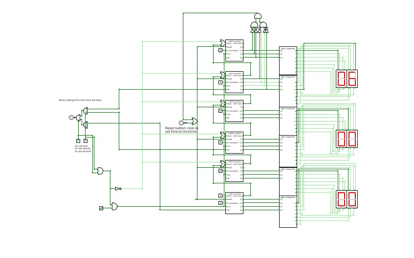
ClockThis is a simple digital clock with basic combinational and sequential logic circuits.
It can display seconds, minutes, and hours
Users can set time by clicking the button and using the multiplexer to choose which to change.
Also, the design for the 4bits 7segment display and 3 bits 7segment display is inside.
ECN-252
ECN-252This is assignment of lab ECN-252 course for CSE student in 4 th semester
Multiplexer
Multiplexermultiplexer
mutiple inputs, single output
multiplexer and demultiplexer
multiplexer and demultiplexermultiplexer
multiplexerexperiment 3
experiment 3dld project
dld project4*1 multiplexer (venkat)
4*1 multiplexer (venkat)8*1 MULTIPLEXER (venkat)
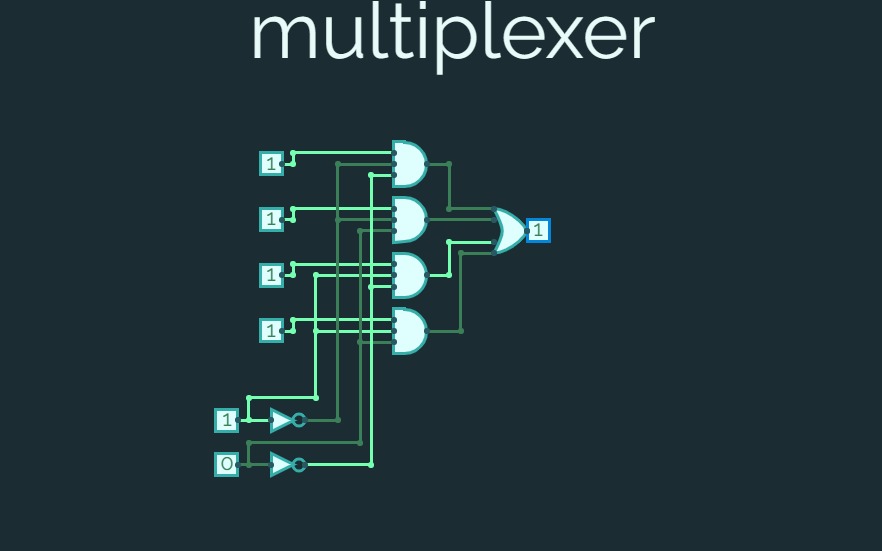
8*1 MULTIPLEXER (venkat)4 to 1 line multiplexer
4 to 1 line multiplexerthis is the implementation of 4 to 1 line multiplexer
Untitled
UntitledMultiplexer Test
Multiplexer Test8:1 using 2:1
8:1 using 2:18 to 1 multiplexer
8 to 1 multiplexerthis is implementation of 8 to 1 multiplexer
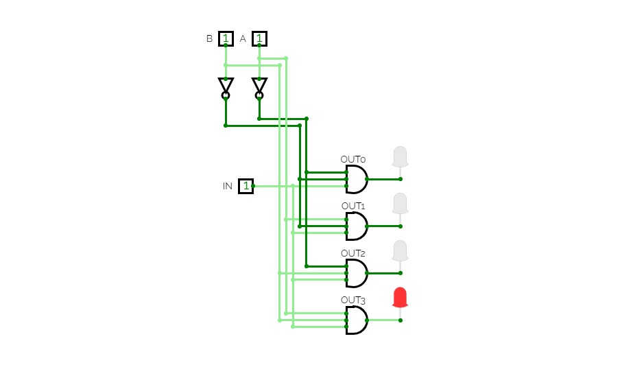
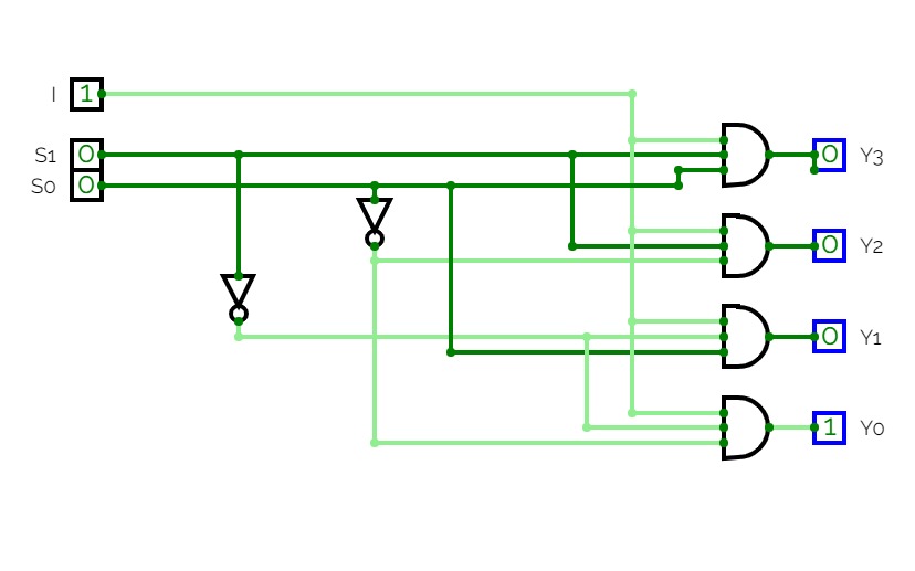
1 X 4 demultiplexer
1 X 4 demultiplexerDE Project 4:1 MUX adder
DE Project 4:1 MUX adderabhishek kumar
abhishek kumarMultiplexer
MultiplexerMultiplexer 8 inputs. 23
Untitled
UntitledUntitled
Untitledmultiplexer
multiplexerUntitled
Untitleddata path of computer from register transfer language
data path of computer from register transfer languageMultiplexer
MultiplexerMultiplexer
MultiplexerMultiplexer
Multiplexerexperiment 7
experiment 7assngn 1
assngn 1multiplexer
64-1 MUX
64-1 MUX64-1 Multiplexer using 2 32-1 MUX and 1 2-1 MUX
Multiplexer and demultiplexer
Multiplexer and demultiplexercoa-10-ayush
coa-10-ayush4:1 Multiplexer
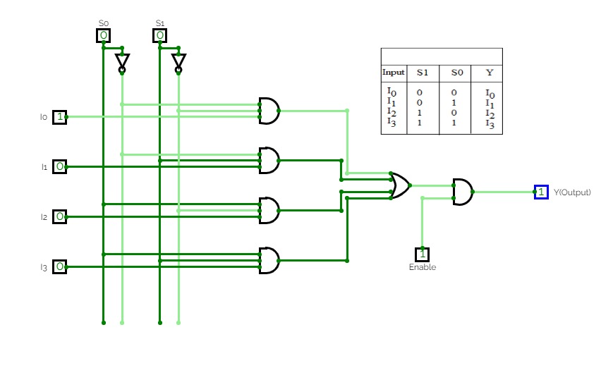
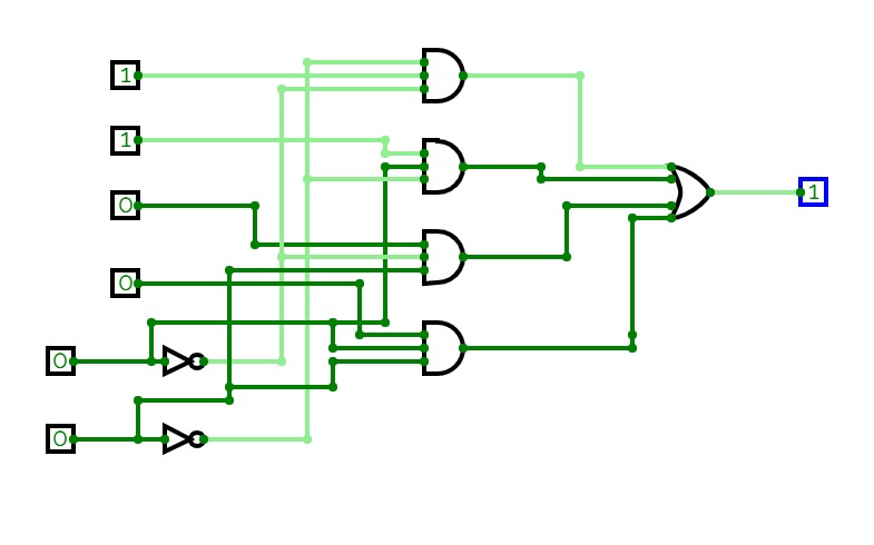
4:1 MultiplexerCircuit shows the 4:1 multiplexer where Each circuit shows the output according to their binary to decimal values
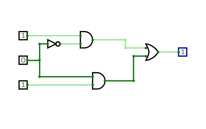
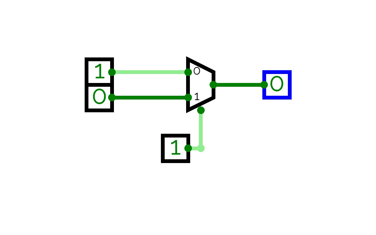
Multiplexer (2:1)
Multiplexer (2:1)multiplexer
multiplexerMultiplexer 4:1
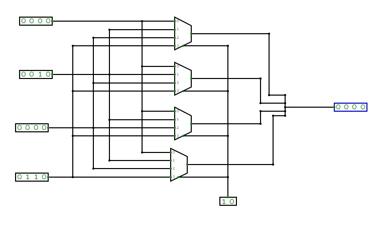
Multiplexer 4:14-bit 4 to 1 multiplexer
4-bit 4 to 1 multiplexerNot entirely sure that this is correct... The 1-bit mux circuit is a breakout of input A through the 4-bit circuit at the top.


