Searched Projects

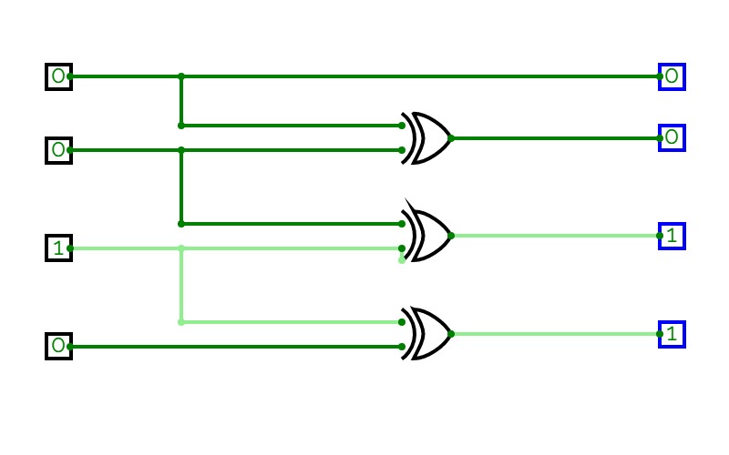
Tags: xor

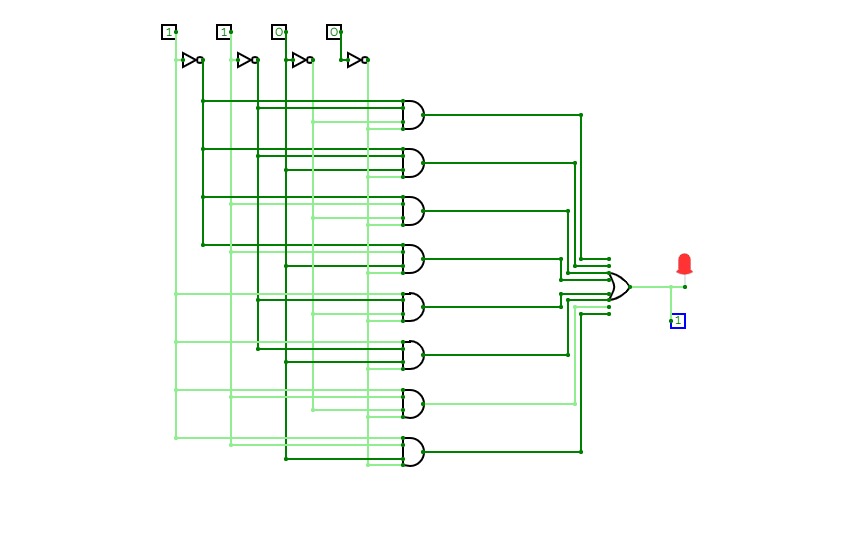
project.name
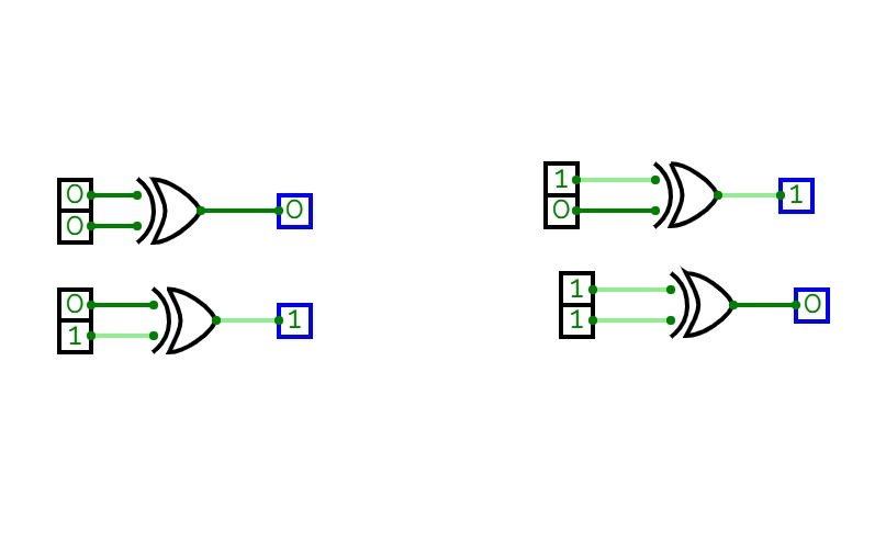
0 Stars     117 Views

Xor

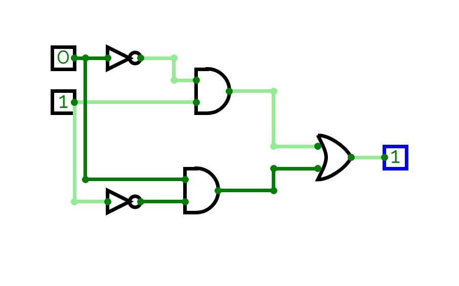
Xor
xor
Xor

project.name
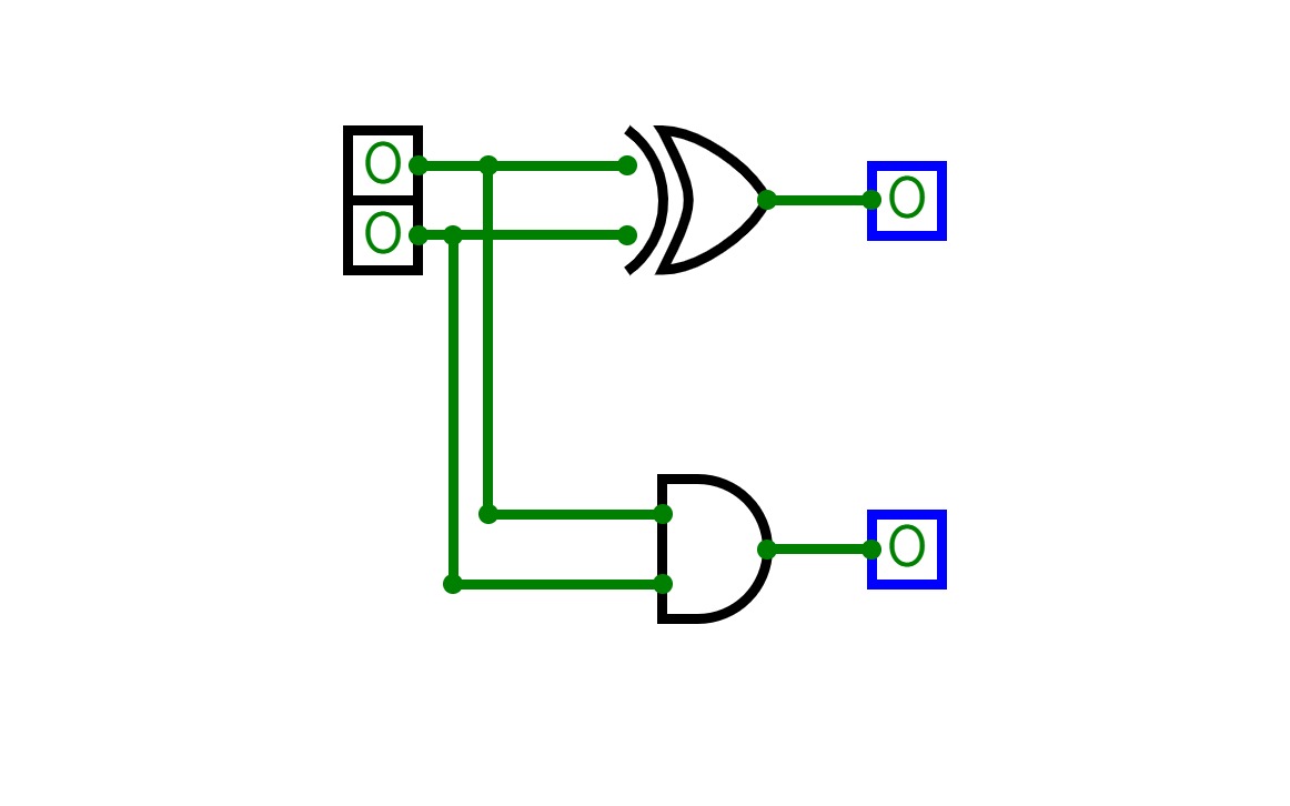
0 Stars     85 Views
User:

xor using nor

xor using nor
xor

project.name
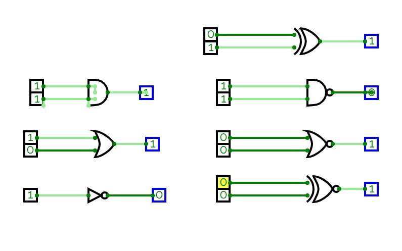
1 Stars     223 Views

Digital Combinational Circuits

Digital Combinational Circuits

Digital Combinational Circuits

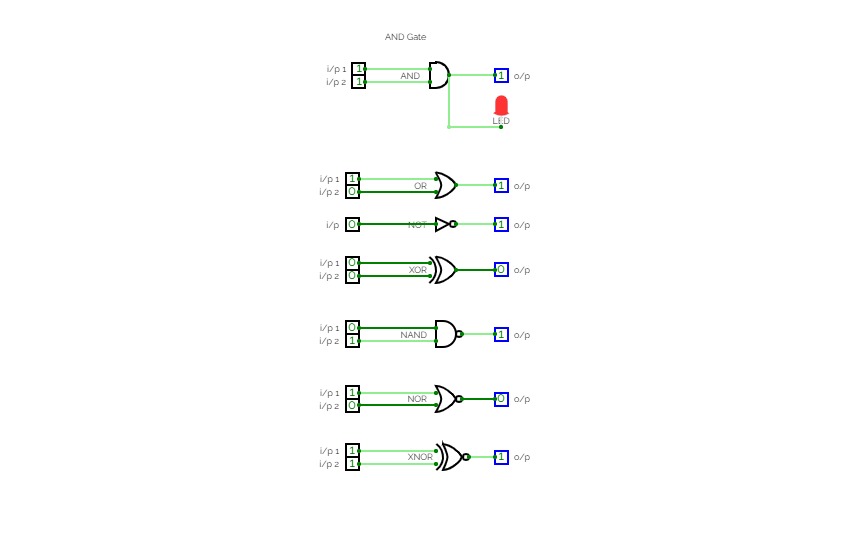
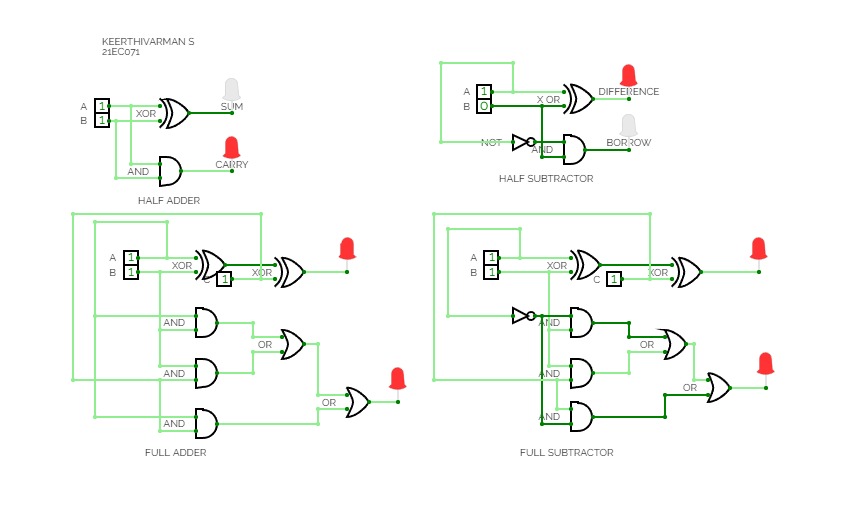
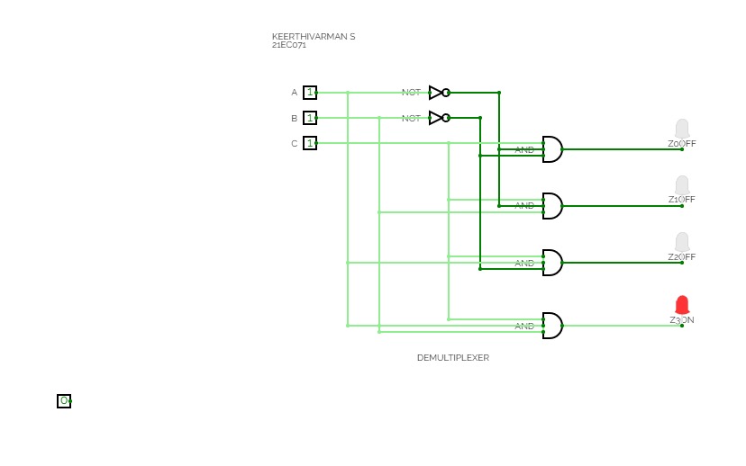
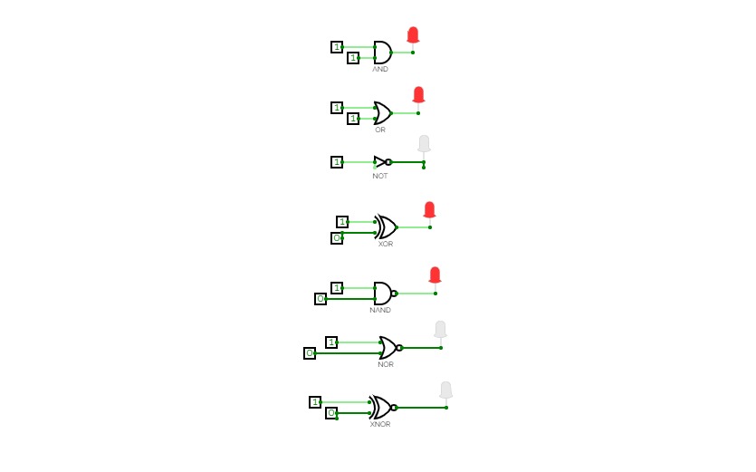
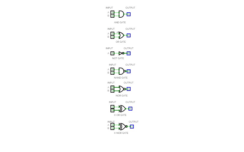
Gates: NOT,  AND, OR, NAND, NOR, XOR, XNOR

half adder, full adder, multiplexer, demultiplexer


project.name
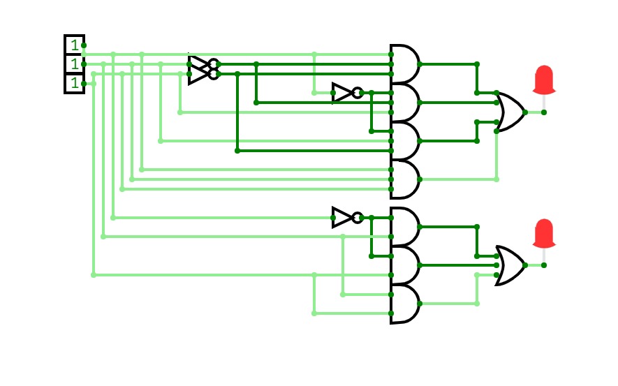
23 Stars     4506 Views
User:
User Image me

This is a CPU witch is capable of executing a lot of stuff in one clock cycle, and this CPU can shift left up to 7 times and shift right up to 7 times witch means that it is possible to  multiply and divide in one clock cycle if you program a table in the program memory. it has a 32 bit instruction width and a 8 bit address. it also has 
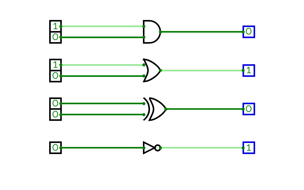
The ALU has the following operations:

  • ADD
  • SUBTRACT
  • SHIFT_LEFT (up to 7 times per cycle 3 bit)
  • SHIFT_RIGHT (up to 7 times per cycle 3 bit)
  • XOR
  • OR
  • NOT

This Was made by miles


project.name
0 Stars     167 Views
User:

dld lab 3

dld lab 3

project.name
0 Stars     66 Views

xor gate

xor gate
xor

project.name
0 Stars     147 Views
User:

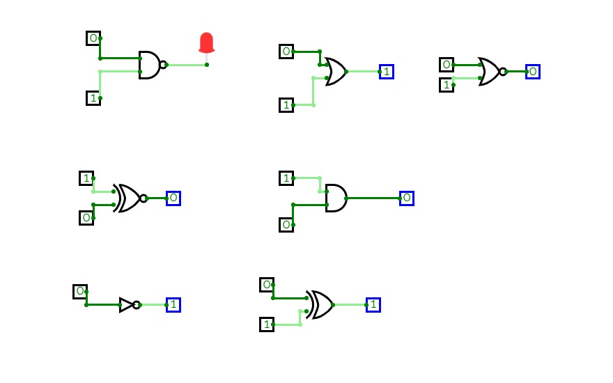
truth table of all gate

truth table of all gate

project.name
0 Stars     80 Views
User:

gates_mux

gates_mux

project.name
0 Stars     134 Views

Assignment 1

Assignment 1

Assignment 1 Lab 22-01-2020


project.name
0 Stars     110 Views
User:

Basic Gates

Basic Gates

Simple Combinational Circuit using AND, OR, XOR, XNOR


project.name
0 Stars     110 Views
User:

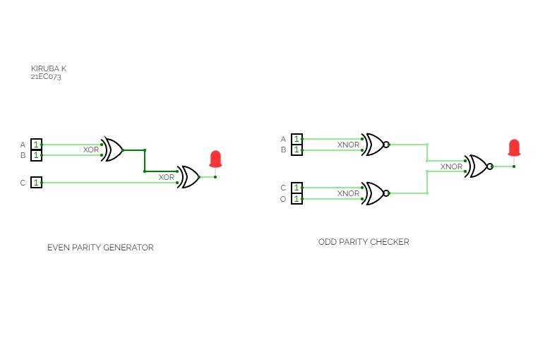
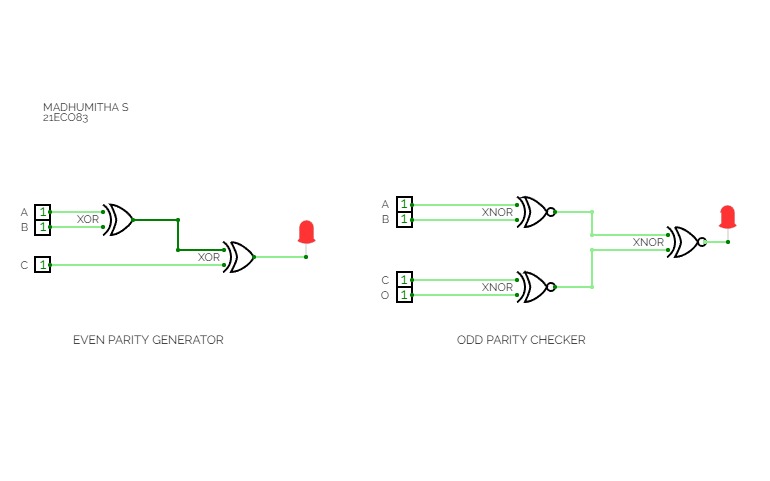
Odd and Even Parity Generator

Odd and Even Parity Generator

project.name
0 Stars     119 Views

Experiment 1:Verifying truth table for gates

Experiment 1:Verifying truth table for gates

project.name
0 Stars     131 Views
User:

3 entrada

3 entrada

aaaaaAum


project.name
0 Stars     136 Views

Verification

Verification

project.name
0 Stars     114 Views
User:

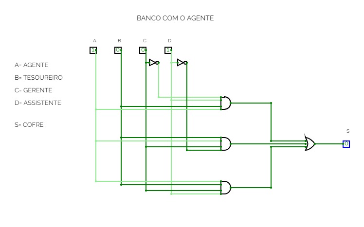
BANCO COM O AGENTE

BANCO COM O AGENTE

BANCO COM O AGENTE


project.name
0 Stars     104 Views
User:

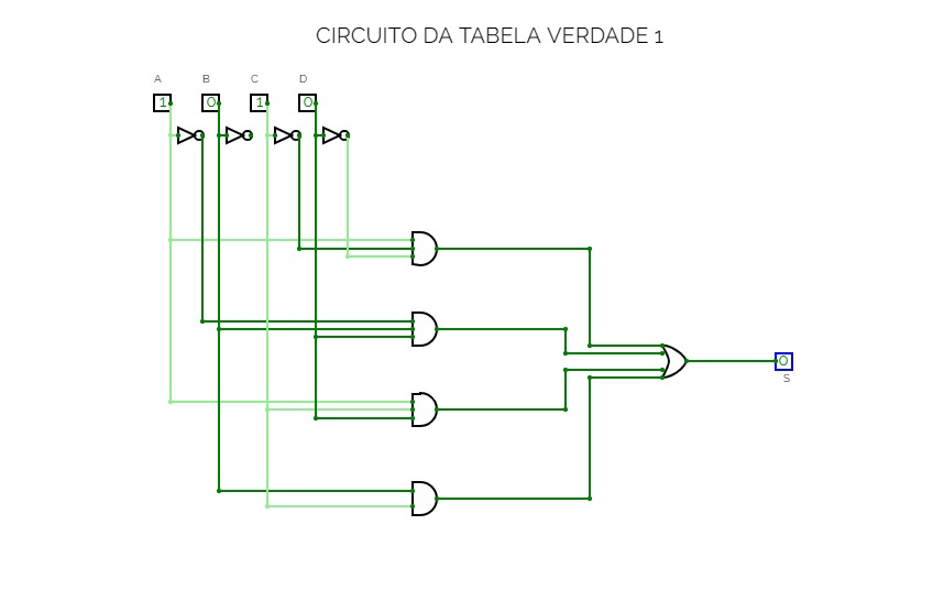
CIRCUITO TABELA VDD 1

CIRCUITO TABELA VDD 1

VGJNHFYTFYTHMKKt


project.name
0 Stars     108 Views
User:

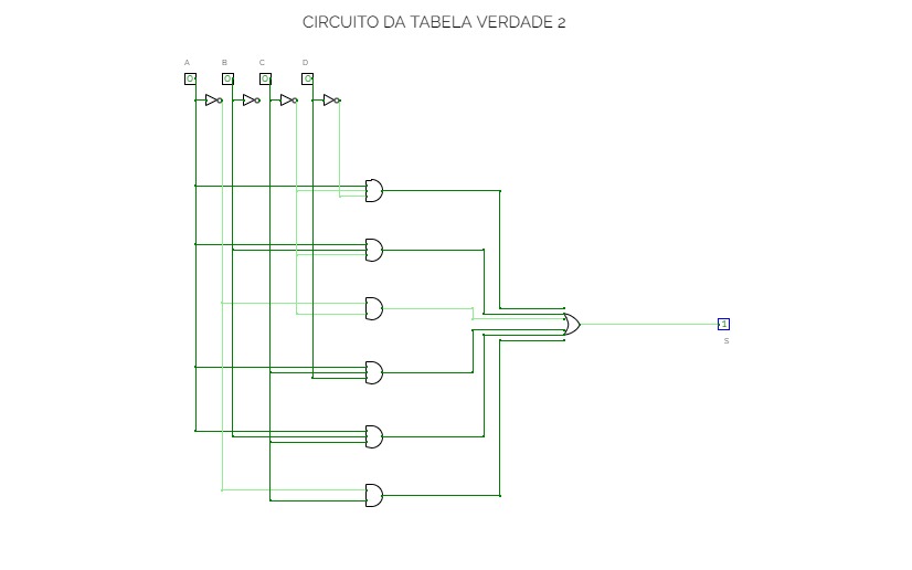
CIRCUITO DA TABELA VDD 2

CIRCUITO DA TABELA VDD 2

TTTTTTTTTTT3R2


project.name
0 Stars     74 Views
User:

SID23

SID23

E4SAZAAAAATerre


project.name
0 Stars     133 Views

gates

gates

project.name
0 Stars     39 Views
User:

xor

xor
xor

project.name
1 Stars     546 Views

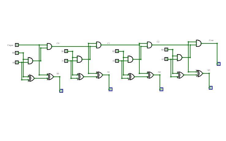
4-bit full adder

4-bit full adder

I'm a beginner, and this is my first circuit. it is 4-bit full adder, which is used to add 3 4-bit input and producing 4-bit or 5-bit output. it is implemented by using XOR gate, AND gate, and OR gate.


project.name
0 Stars     14 Views

shubhankar anand

shubhankar anand
xor

project.name
0 Stars     15 Views

shubhankar

shubhankar
xor

project.name
0 Stars     48 Views

01_basic gate

01_basic gate

project.name
0 Stars     80 Views

full subtracter

full subtracter

project.name
0 Stars     22 Views

4bit adder subtractor

4bit adder subtractor

project.name
0 Stars     81 Views

full adder

full adder

project.name
0 Stars     69 Views

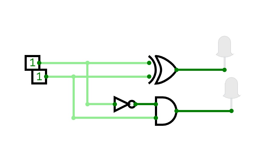
half subtractor

half subtractor

project.name
0 Stars     75 Views

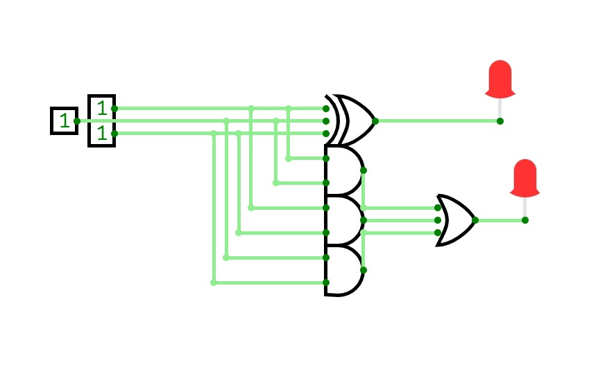
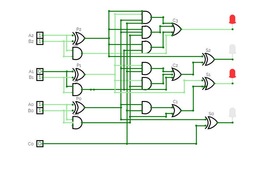
3-bit carry look-ahead adder

3-bit carry look-ahead adder

project.name
0 Stars     72 Views

full wave

full wave

project.name
0 Stars     81 Views
User:

full and half

full and half

project.name
0 Stars     76 Views
User:

half

half

project.name
0 Stars     84 Views
User:

full

full

project.name
0 Stars     35 Views

full

full

project.name
0 Stars     36 Views

demultiplexef

demultiplexef

project.name
0 Stars     64 Views

EXPERIMENT 0 Basic gates

EXPERIMENT 0 Basic gates

project.name
0 Stars     95 Views

homework

homework

project.name
0 Stars     28 Views
User:

even and odd

even and odd

project.name
0 Stars     23 Views
User:

even and odd

even and odd

project.name
0 Stars     9 Views
User:

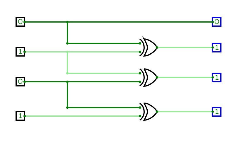
binary to gray

binary to gray
xor

project.name
0 Stars     10 Views
User:

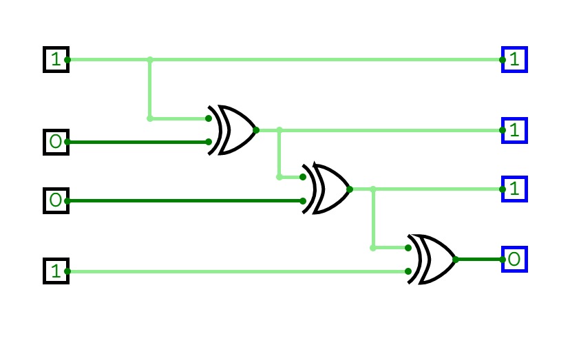
gray to binary

gray to binary
xor

project.name
0 Stars     11 Views
User:

or and not

or and not
xor

project.name
0 Stars     11 Views

binary to gray

binary to gray
xor

project.name
0 Stars     12 Views
User:

i love xor

i love xor
xor

i love xor


project.name
0 Stars     6 Views
User:

Xor

Xor
xor

xor


project.name
0 Stars     164 Views
User:

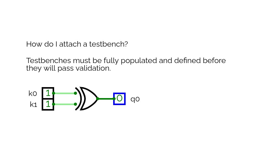
Testbench test

Testbench test

A basic test of how to attach a testbench and name/save a project.


project.name
0 Stars     8 Views

learning

learning
xor

project.name
0 Stars     50 Views

experiment 1 level 1

experiment 1 level 1

project.name
0 Stars     47 Views

shubham verma

shubham verma

project.name
0 Stars     13 Views

Grey To Binary

Grey To Binary
xor

project.name
0 Stars     23 Views

Untitled

Untitled

project.name
0 Stars     14 Views

2 way switch

2 way switch

project.name
0 Stars     5 Views
User:

Untitled

Untitled
xor

project.name
0 Stars     10 Views
User:

XOR gate

XOR gate

project.name
0 Stars     4 Views

11septlab

11septlab

project.name
0 Stars     7 Views

Porta Lógica

Porta Lógica

O que são Portas Lógicas?

Portas lógicas são os blocos fundamentais da eletrônica digital, responsáveis pela realização das operações lógicas básicas que formam a base dos circuitos digitais. Elas recebem um ou mais sinais de entrada e produzem um sinal de saída, conforme uma lógica específica. As portas lógicas são essenciais em computadores, dispositivos eletrônicos e em diversas aplicações tecnológicas, pois são usadas para executar operações como soma, subtração, comparação, e outras funções lógicas necessárias para o funcionamento de sistemas digitais.

Cada porta lógica tem uma função definida e pode ser representada por um símbolo específico em diagramas elétricos. As operações realizadas por essas portas são baseadas nas leis da lógica matemática, particularmente na álgebra booleana, que permite a manipulação de variáveis binárias (0 e 1).