
Two 3-bit number Adder
Two 3-bit number AdderA circuit that adds two 3-bit numbers using a half-adder and a full-adder.
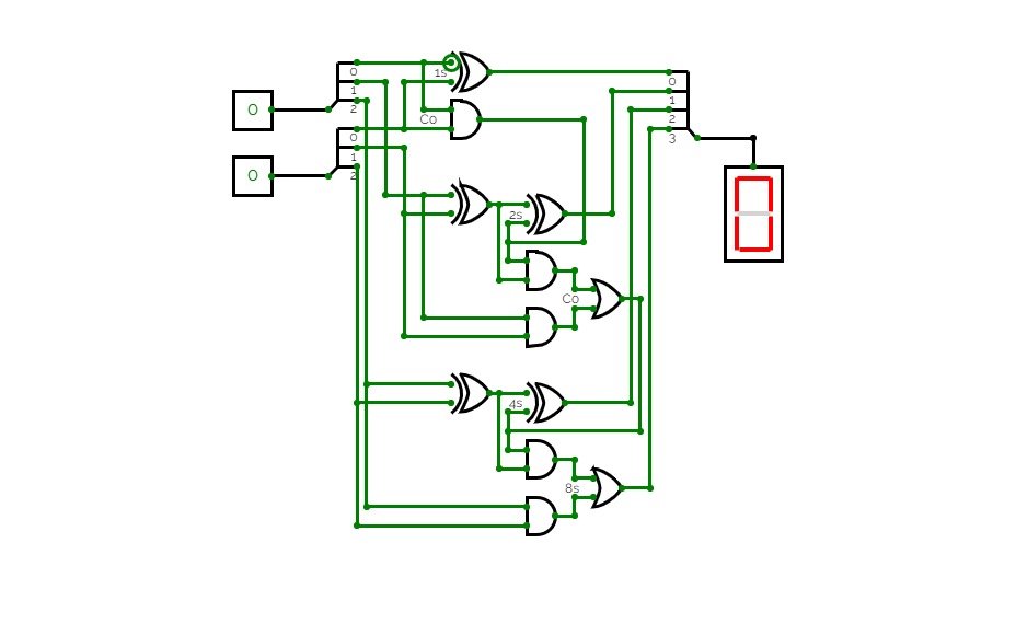
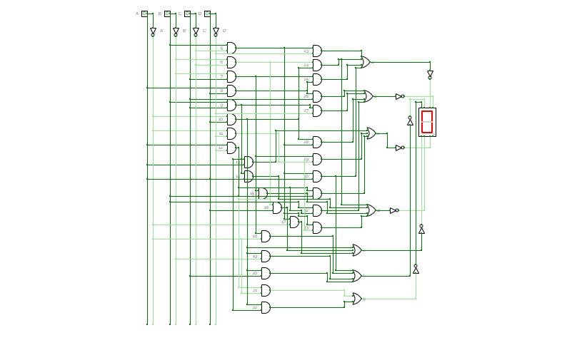
A circuit that takes two decimal numbers A and B as input and then splits in into their corresponding three bits using a splitter and then calculates their summation using XOR, AND and OR gates. This generates 4 output lines for 4 bits of the summation, and a reversed splitter is finally used to join the output lines to produce a 4-bit output and displayed using a Hex-Display.
This is a ripple-carry adder.
bintohex
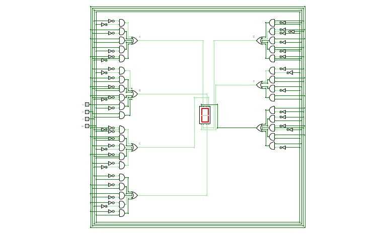
bintohexThe circuit was made by a beginner to get some experience working with logic gates, k-maps and simulation software, there are many things that can be improved. Open for suggestions.

Binary Adders
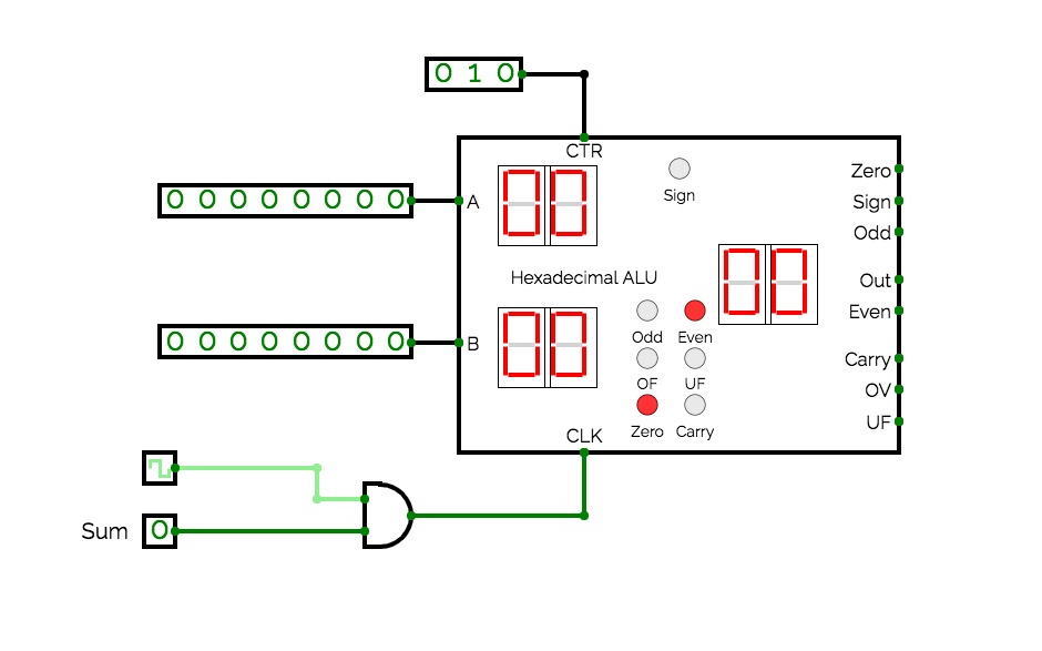
Binary AddersA collection of binary adders with Binary, Hex, and Decimal input and output representation
Untitled
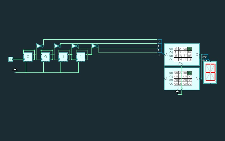
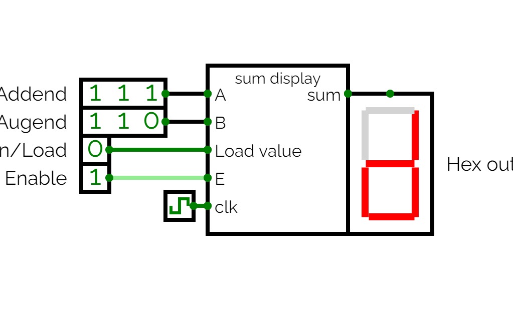
Untitled3-bit sequential adder that saves the output sum to a 4-bit shift register and displays the output on a hex 7-segment display.


