Full Adder
Full AdderFull Adder Ripple
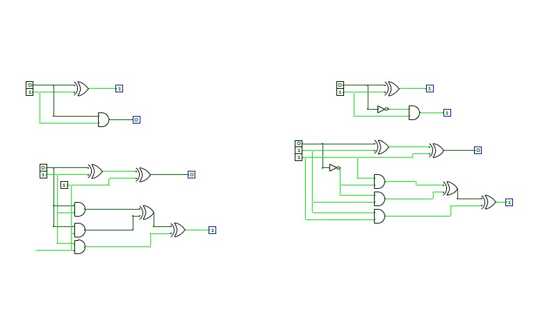
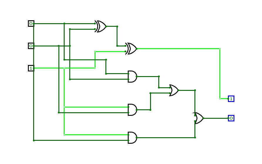
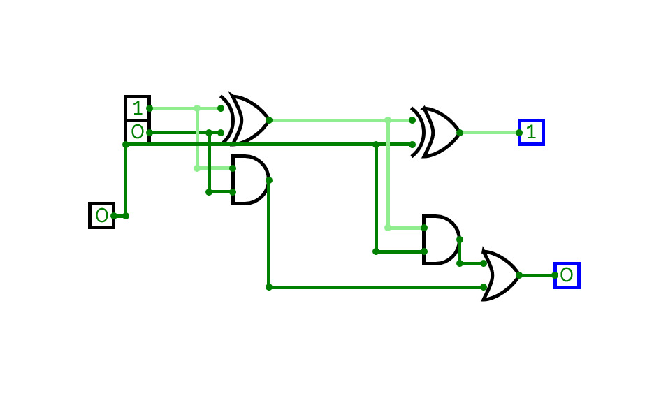
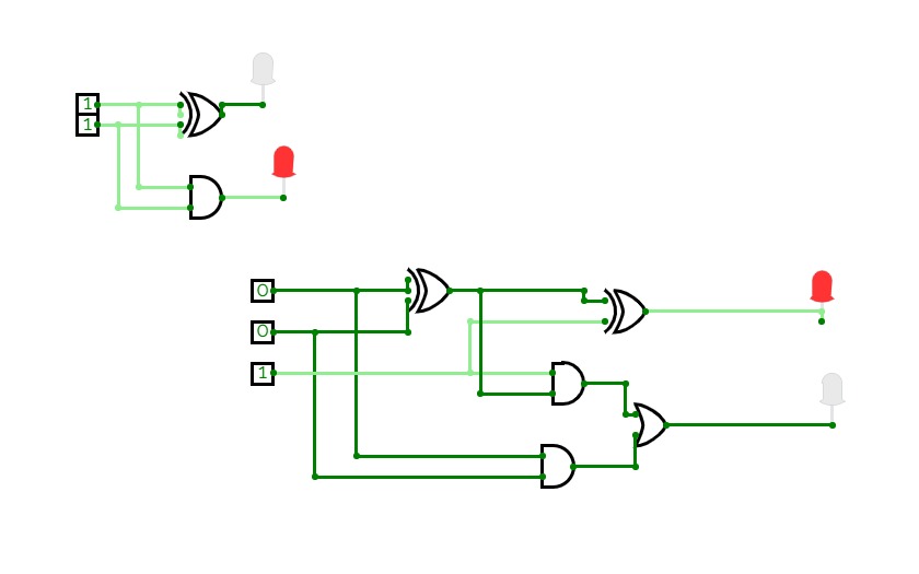
Full Adder RippleA Full Adder with two inputs and one carry input representing two numbers to add. Three Full Adders in a Ripple representing three digit numbers. A XOR gate representing overflow.
Experiment -2 SAHIL JAIN
Experiment -2 SAHIL JAINExperiment-2
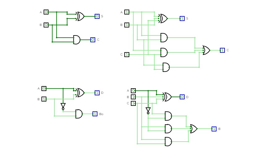
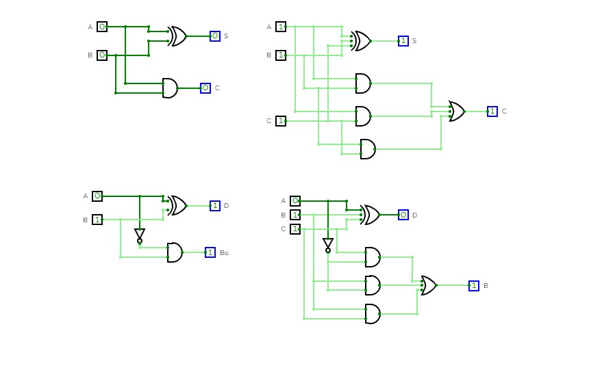
Experiment-2Half Adder, Half Subtracter, Full Adder, Full Subtracter
Full Adder
Full AdderFull Adder
Full AdderFull Adder
Full AdderHow to make Full Adder
SumadorRestador
SumadorRestadorFull Adder
Full AdderFull Adder
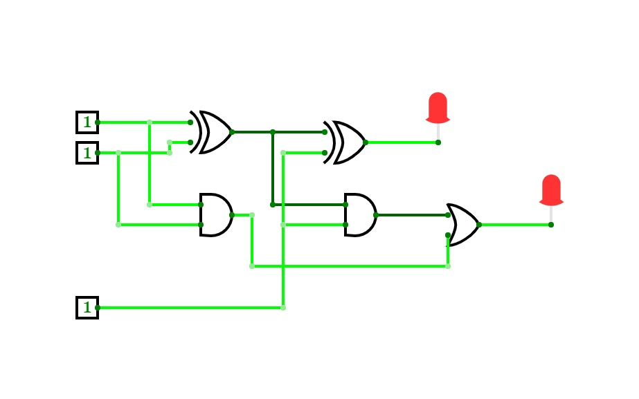
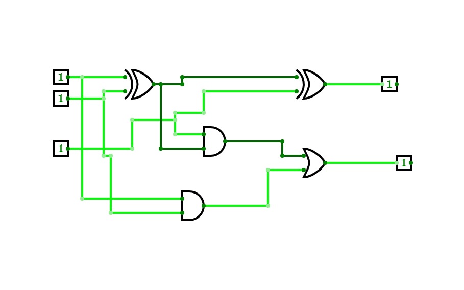
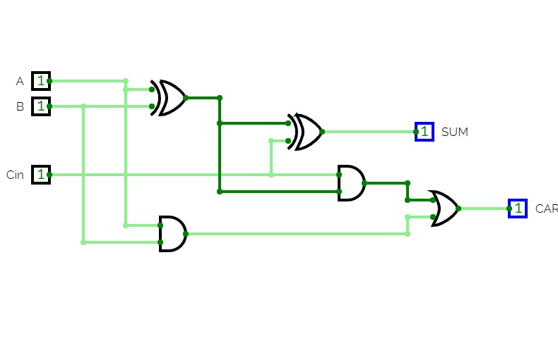
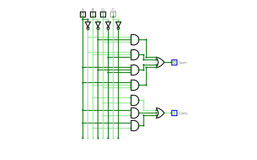
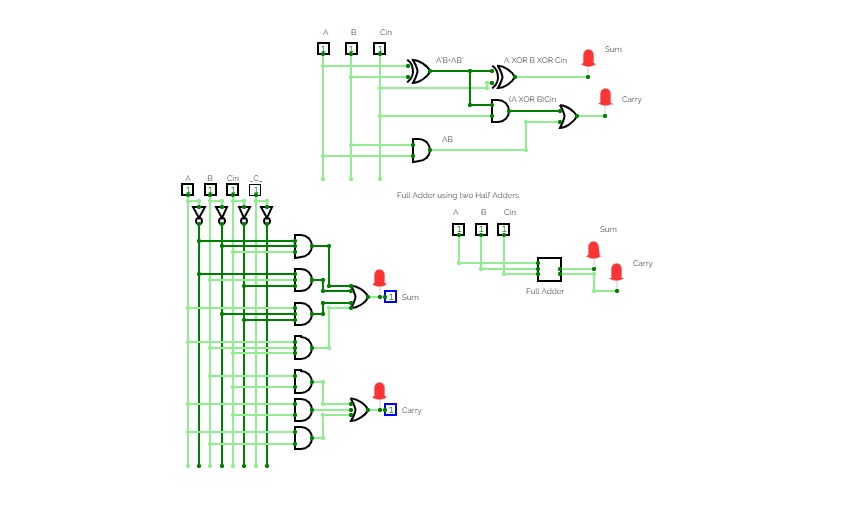
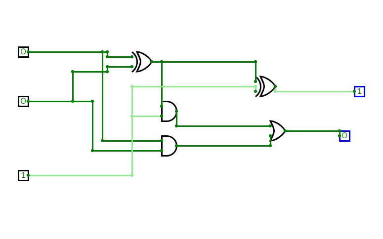
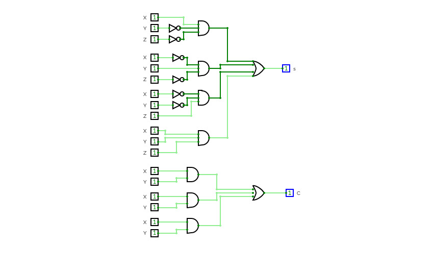
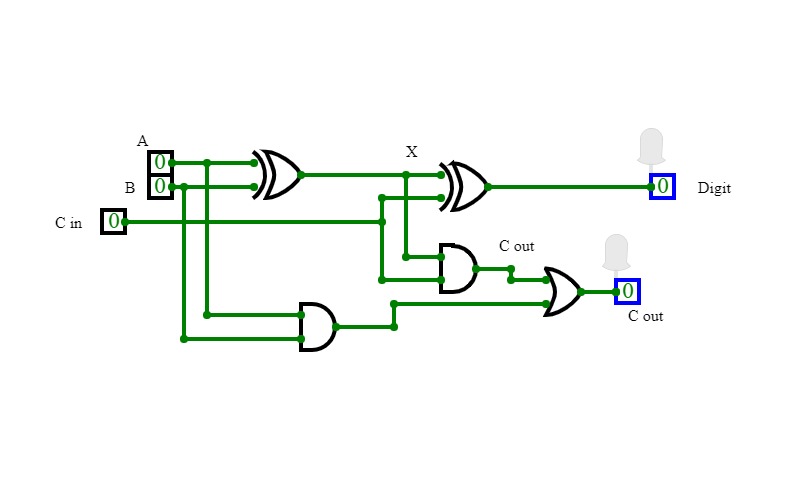
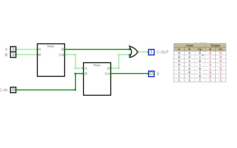
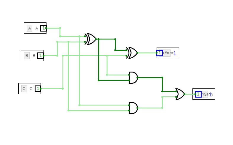
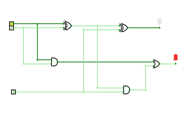
Full AdderMy first attempt at an full adder. This is a logical circuit that performs an addition operation on three one bit binary numbers. The full adder produces a sum of three inputs and a carry value.
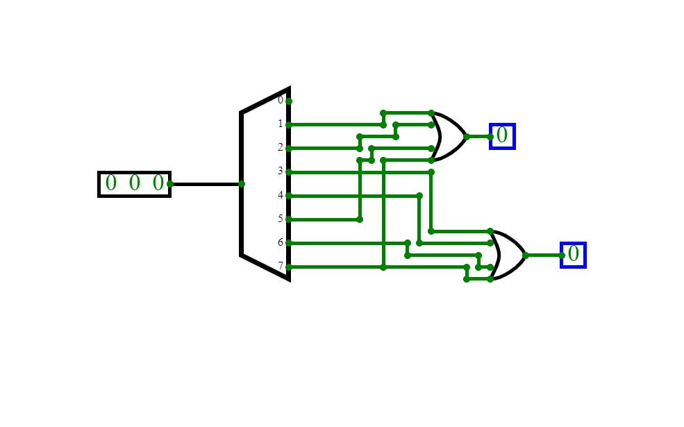
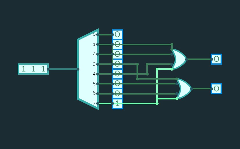
Full Adder Using Decoder IC 74138
Full Adder Using Decoder IC 74138Experiment 3
Experiment 3HALF ADDER , FULL ADDER
HALF ADDER , FULL ADDERHalf Adder And Full Adder
Half Adder And Full AdderProject 2
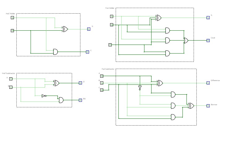
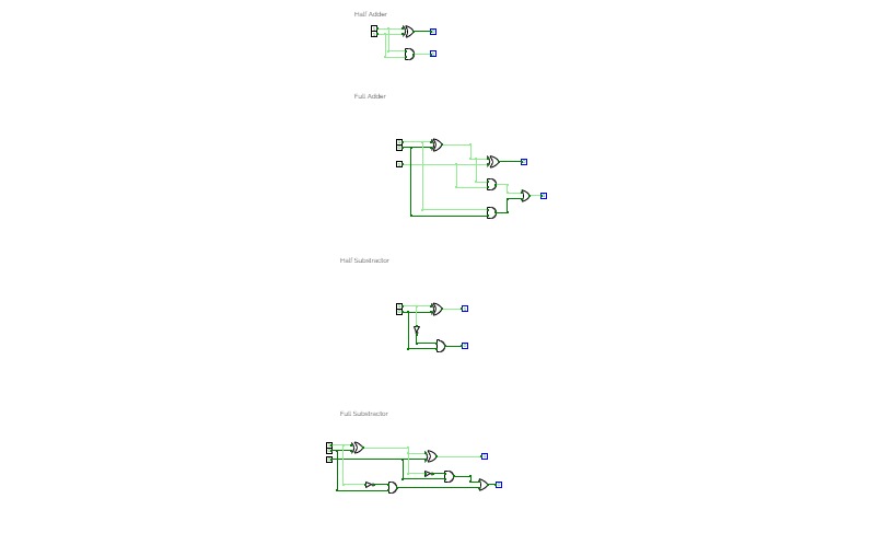
Project 2Implement Half Adder, Full Adder, Half Subtractor and Full Subtractor.
project 3
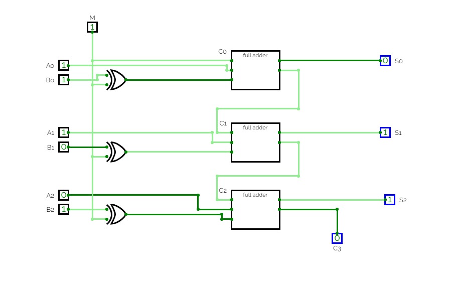
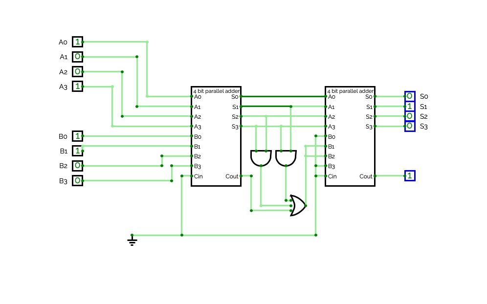
project 3Implement 3-bit parallel Binary Adder/Subtractor
Project 2
Project 2Half Adder, Full Adder, Half Subtractor, Full Subtractor.
Full Adder
Full AdderPARALLEL ADDER
PARALLEL ADDERI Design Parallel Adder
Lab 4.2 (Full Adder)
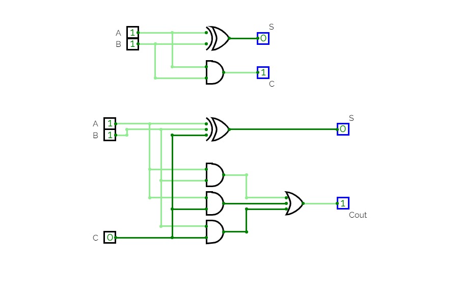
Lab 4.2 (Full Adder)Half adder
Half adderFull Adder and subtractor
Full Adder and subtractorI like eating breakfast as any meal of day.
Adder
AdderAdder: Half and Full Adder
Adder: Half and Full AdderFull Adder and more
Full Adder and moreA 1-bit full adder, 1-bit adder/subtractor, and a 4-function single-output-bit ALU
Adders
AddersDemonstration models for students in a basic business information systems lecture.
Untitled
Untitledhalf Adder and Full Adder
half Adder and Full AdderAdder Circuit - Half & Full
Adder Circuit - Half & FullFull Adder
Full AdderFull Adder
Full Adder
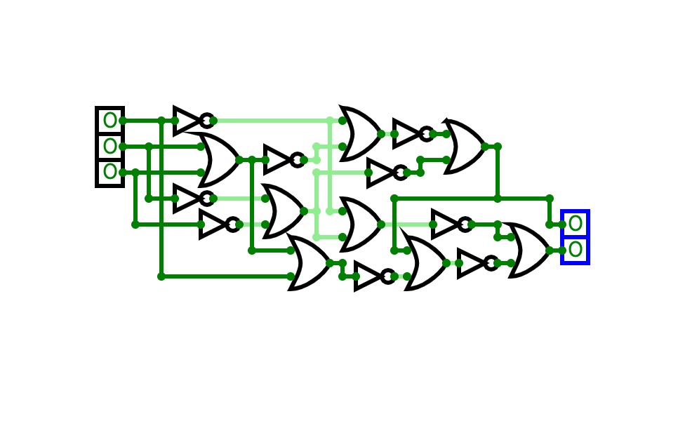
Full AdderFull Adder made from NOT and OR gates
Experiment 2
Experiment 2Experiment 2 of Digital Electronics lab
Somador Completo
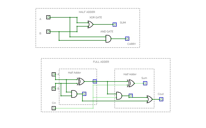
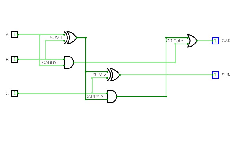
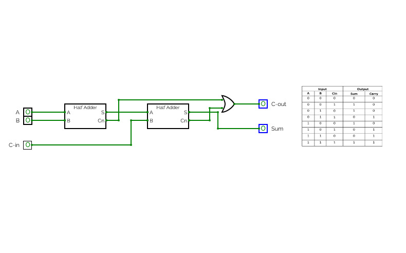
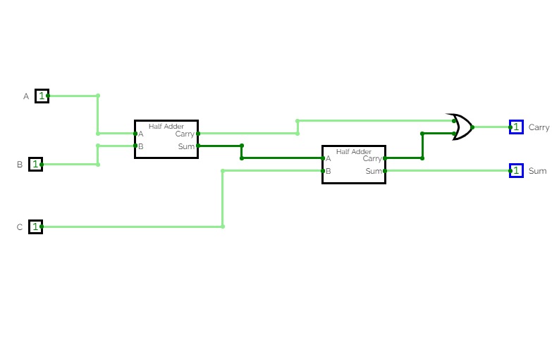
Somador CompletoFull Adder using 2 x Half Adder
Full Adder using 2 x Half AdderFull Adder
Full AdderLab 1 Ques 2 Full Adder
Lab 1 Ques 2 Full AdderFull Adder
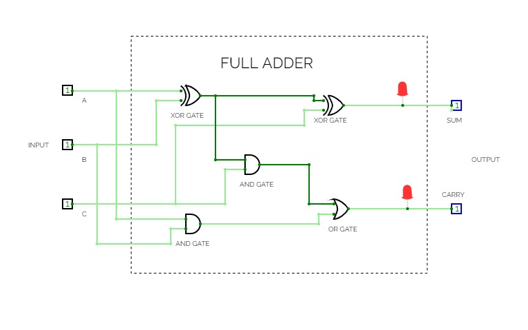
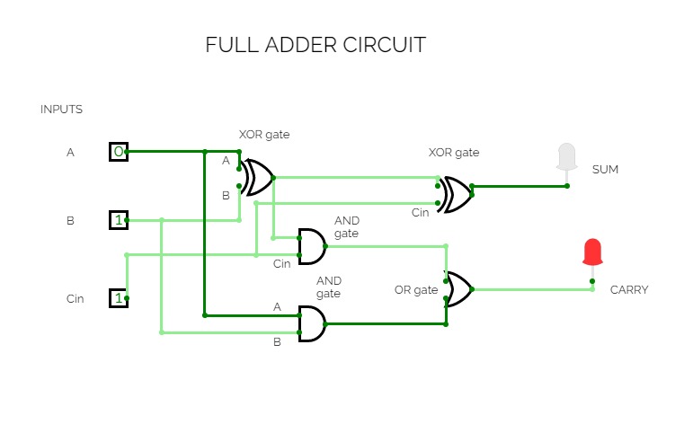
Full AdderThis is Full Adder Circuit Diagram
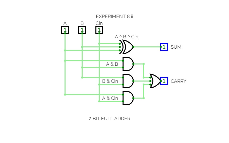
EXPERIMENT 8 ii
EXPERIMENT 8 iiImplement a Full adder using basic gates
EXPERIMENT 9
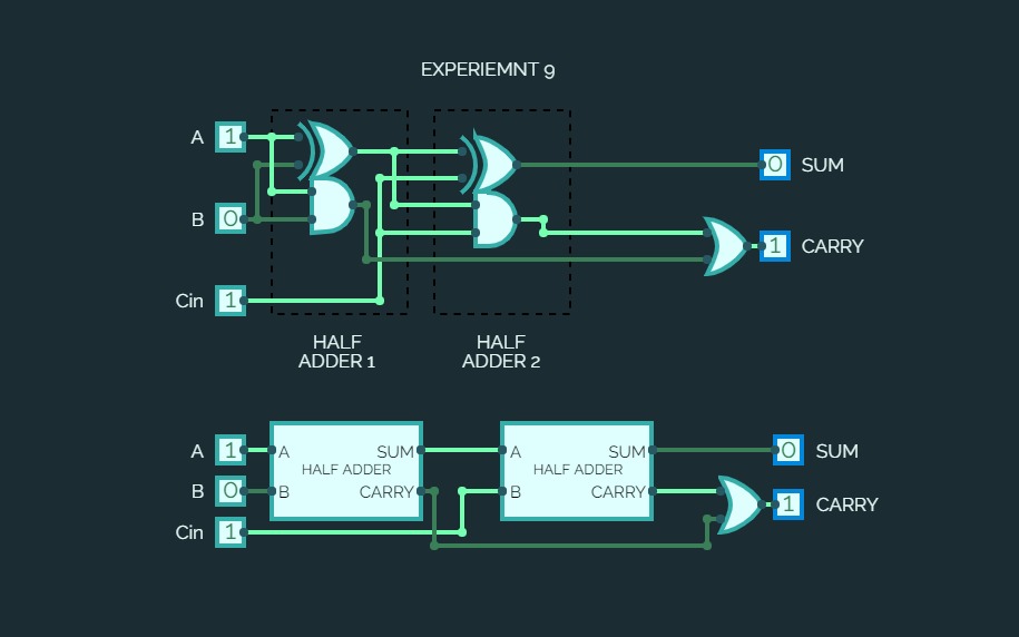
EXPERIMENT 9Implement a Full adder using 2 Half Adders
Soumya P3
Soumya P3Final
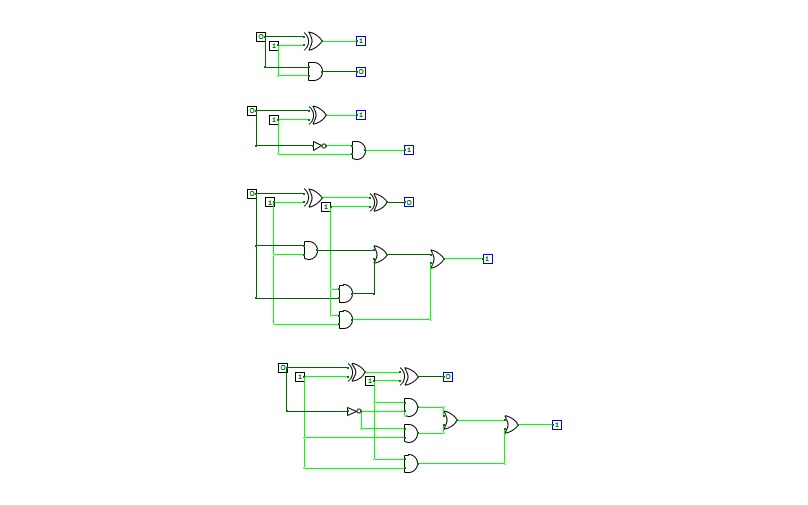
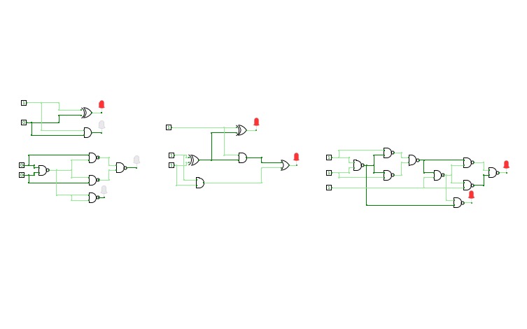
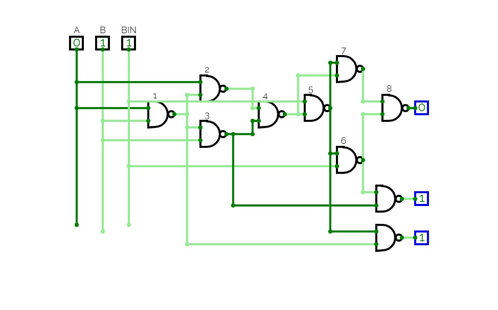
FinalHalf Adder, Half Subtractor, Full Adder, Full Subtractor with its NAND implementation.
4 bit Arithmetic unit
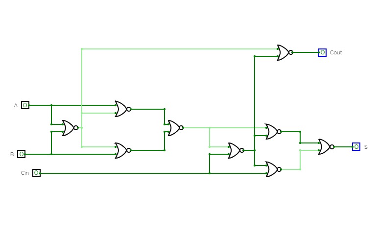
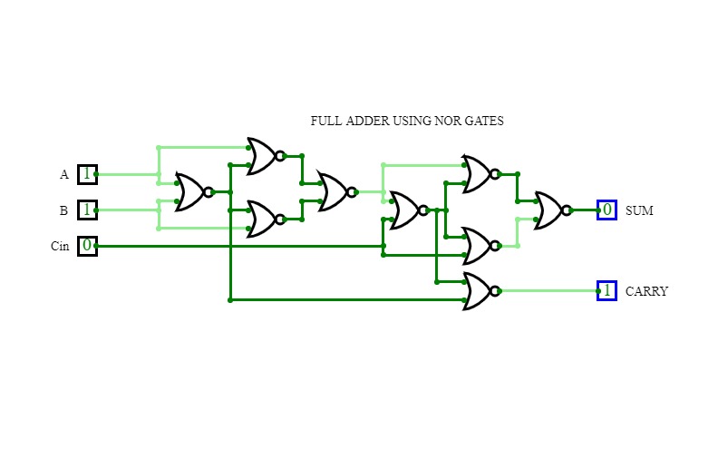
4 bit Arithmetic unitFull Adder using NOR gate
Full Adder using NOR gateECL Lab 2
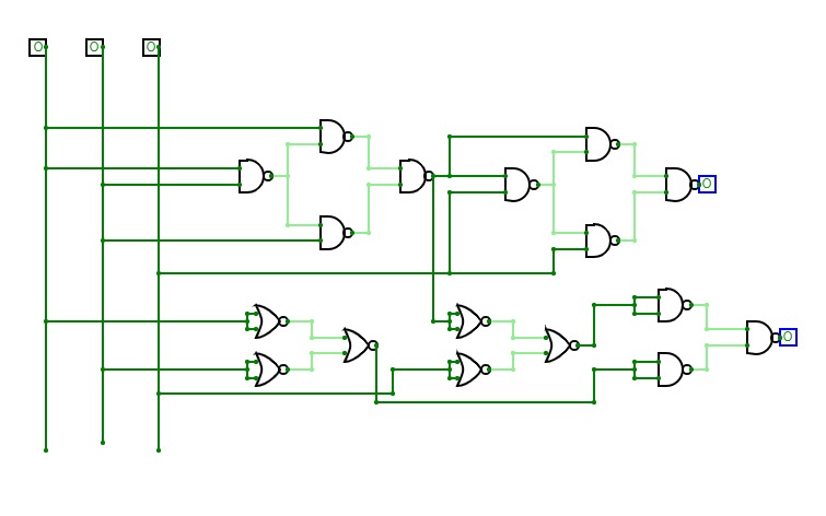
ECL Lab 2Full adder using Nor gates only
Full adder using Nor gates onlyUntitled
UntitledClassification of Combinational circuit
Untitled
UntitledHi pwede mag hello
Adders Circuit
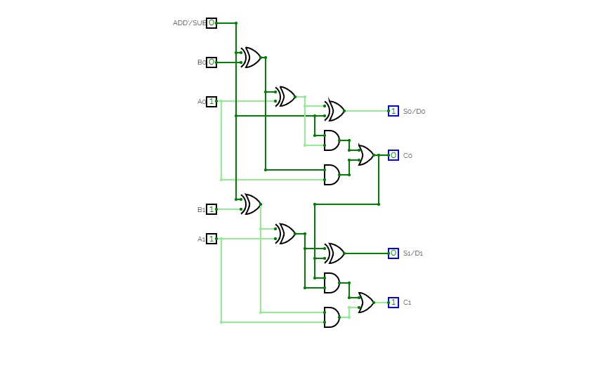
Adders Circuit2-Bit Full Adder Subtractor
2-Bit Full Adder Subtractor2 Stage Adder/Subtractor
Adders and Subtractors
Adders and Subtractors4 Bit Parallel Adder
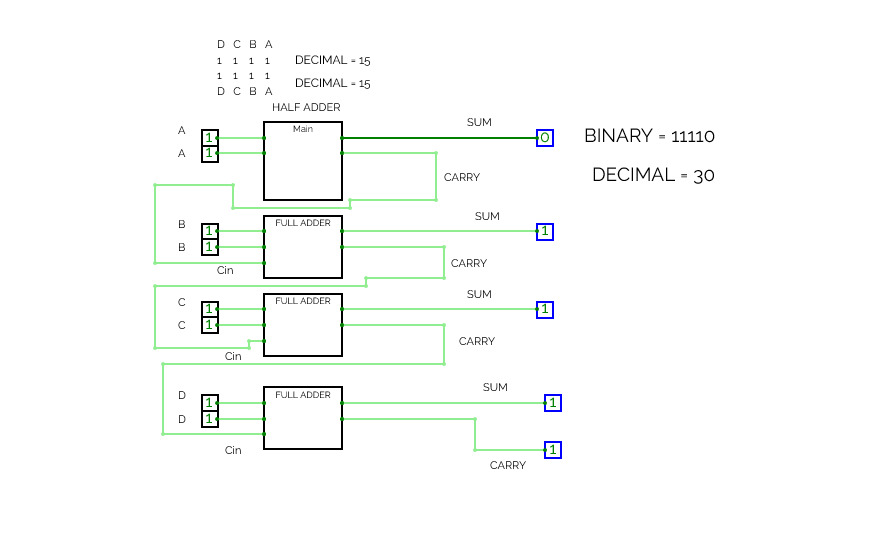
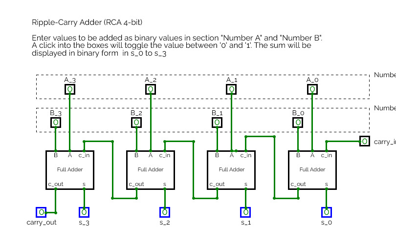
4 Bit Parallel AdderIn the preceding section, we discussed how two binary bits can be added and the addition of two binary bits with a carry. In practical situations it is required to add two data each containing more than one bit. Two binary numbers each of n bits can be added by means of a full adder circuit. Consider the example that two 4-bit binary numbers B 4B 3B 2B 1 and A 4A 3A 2A 1 are to be added with a carry input C 1. This can be done by cascading four full adder circuits as shown in Figure 5.48. The least significant bits A 1, B 1, and C 1 are added to the produce sum output S 1 and carry output C 2. Carry output C 2 is then added to the next significant bits A 2 and B 2 producing sum output S 2 and carry output C 3. C 3 is then added to A 3 and B 3 and so on. Thus finally producing the four-bit sum output S 4S 3S 2S 1 and final carry output Cout. Such type of four-bit binary adder is commercially available in an IC package.
Combinational Circuits
Combinational CircuitsImplement and verify Combinational Circuits
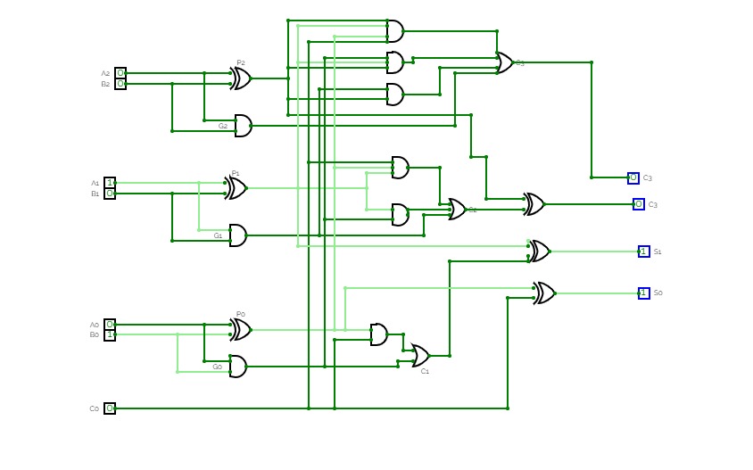
3 bit Carry Look Ahead Adder
3 bit Carry Look Ahead Addersample input
A2A1A0= 110
B2B1B0= 101
expected output
S2S1S0 = 011, C3= 1
Adders
AddersBinary Adders
Binary AddersA collection of binary adders with Binary, Hex, and Decimal input and output representation
Full Adder using BOTH NAND and NOR gates.
Full Adder using BOTH NAND and NOR gates.Full Adder using BOTH NAND and NOR gates.
1BitFullAdder
1BitFullAdder1 bit full adder, propagated carry and generated carry outputs.
Full Adder by Souvik Ghosh
Full Adder by Souvik GhoshFull Adder
Full Adderfull Adder Circuit by Muhammad Usman Tayyab
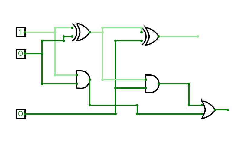
couldn't add A B C inputs so used 1 and 0 instead
question number 2 from 1 -5
24060123140045_DewiLarasatiMumpuni_pertemuan3
24060123140045_DewiLarasatiMumpuni_pertemuan3Dewi Larasati Mumpuni (24060123140045)
Mutiara Ayu Pramono, 24060123140131, Minggu 3
Mutiara Ayu Pramono, 24060123140131, Minggu 3Full Adder using Decoder
Full Adder using DecoderFULL ADDER
FULL ADDERFull Adder
Full AdderDigital Electronics
Digital ElectronicsR-S Flip flop
D flip flop
J-K flip flop
T flip flop
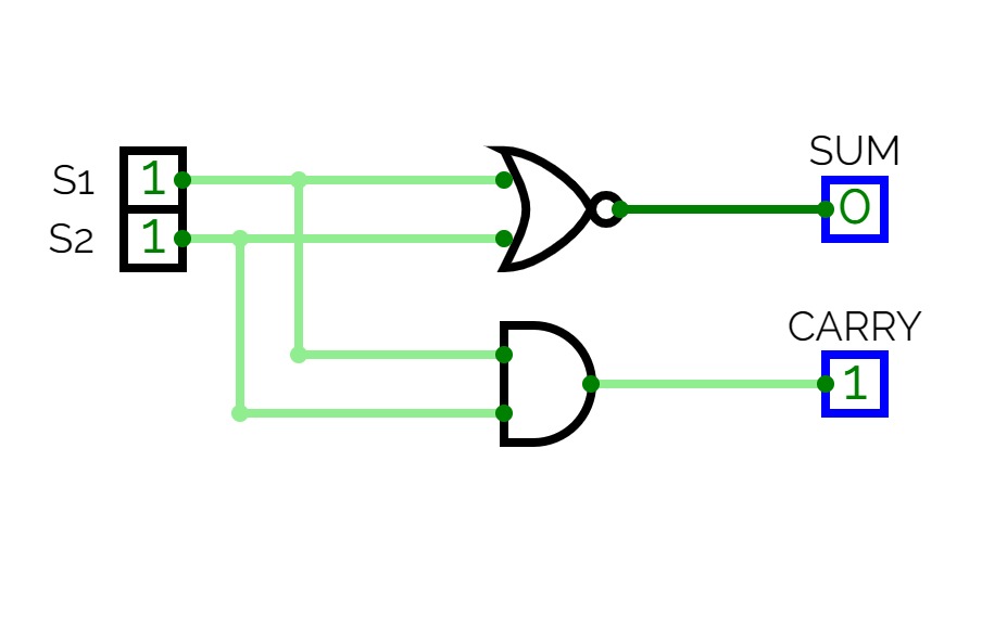
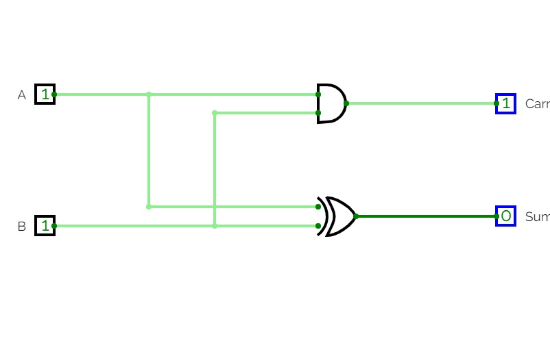
Half Adder
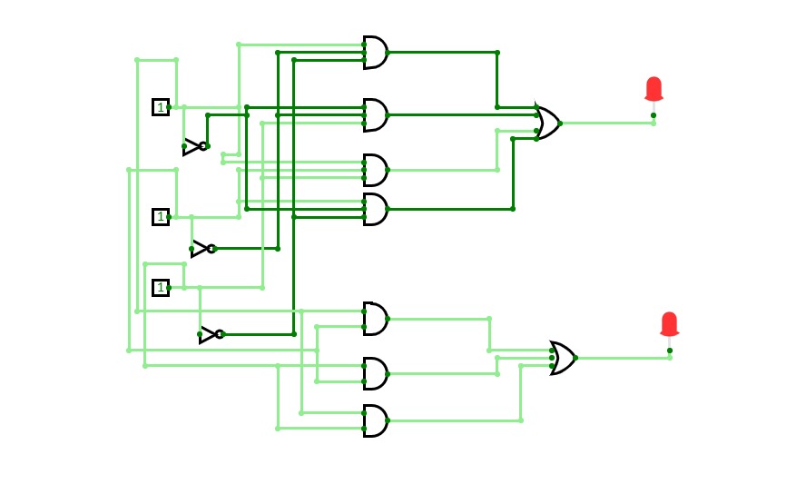
Full Adder
Half Subtractor
Full Subtractor
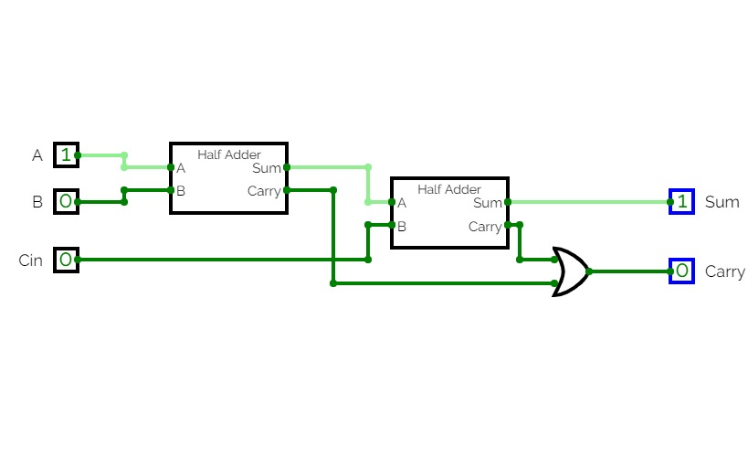
1 Bit Full adder Using Half Adder
1 Bit Full adder Using Half AdderFull adder using Half adder
1Bit Full adder gate Alone
1Bit Full adder gate Alone1Bit Full adder gate Alone
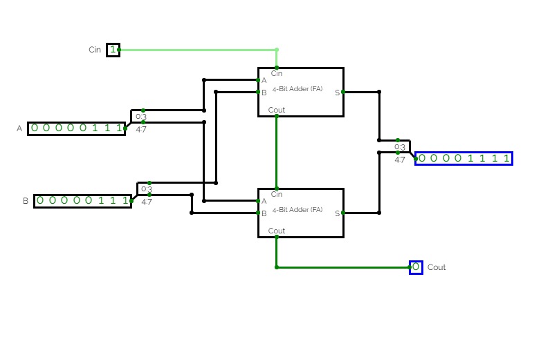
4 Bit Full Adder
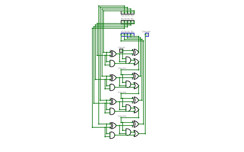
4 Bit Full Adder4 Bit Full Adder that can add any two 4 bit representable numbers and has a flag for CarryOut of the most significant bit
Full adder
Full adderFull Adder
Adders
AddersProject 1,2
Full adder using two Half Adder by Mohammad Salman 201-15-14165
Full adder using two Half Adder by Mohammad Salman 201-15-14165Full adder using two Half Adder by Mohammad Salman 201-15-14165
2310994564 Adders Subtractors
2310994564 Adders SubtractorsFullAdder
FullAdder22BCY10180 FULL ADDER
22BCY10180 FULL ADDERFull Adder
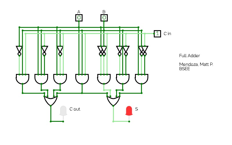
Full AdderClásico circuito de un sumador completo A, B y acarreo de entrada (Cin) que genera el bit de suma y el acarreo (Cout).
Este sumador lo usaré en un sumador de múltiples bits y en un Sumador/Restador (suma del complemento a 2 del sustraendo), posiblemente en una ALU incipiente también.
Full Adder
Full AdderFull Adder
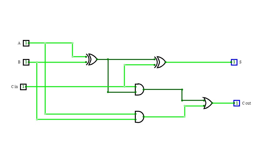
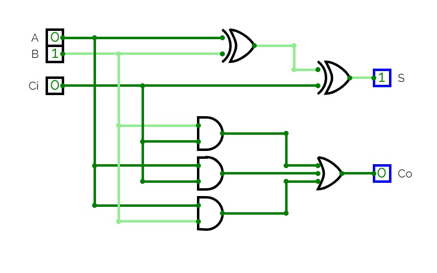
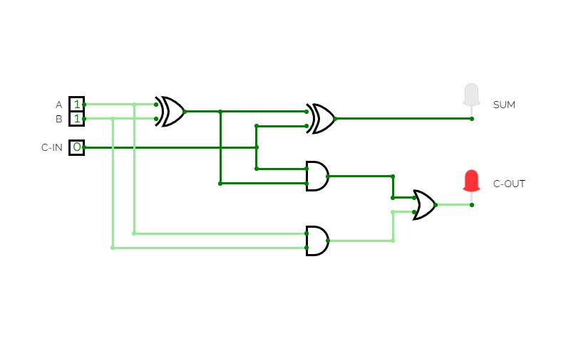
Full AdderThis is a simple digital logic circuit diagram for full adder using A,B and Cin as input and then Sum and Cout as output.
Half Adder and Full Adder
Half Adder and Full AdderAkmal Kafli Anan_24060124120042_A1
Akmal Kafli Anan_24060124120042_A1Arga Yura Danendra_24060124140191_A1
Arga Yura Danendra_24060124140191_A1Half Adder, Full Adder
Half Adder, Full AdderAron Sorimuda Johanes Pasaribu_24060124130086_A1
Aron Sorimuda Johanes Pasaribu_24060124130086_A1Pertemuan 3 Dasis A1
Informatika Kelas A 2024
Membuat rangkaian Half Adder, Full Adder, Seven Segment Display
4 Bit Full Adder/Subtractor
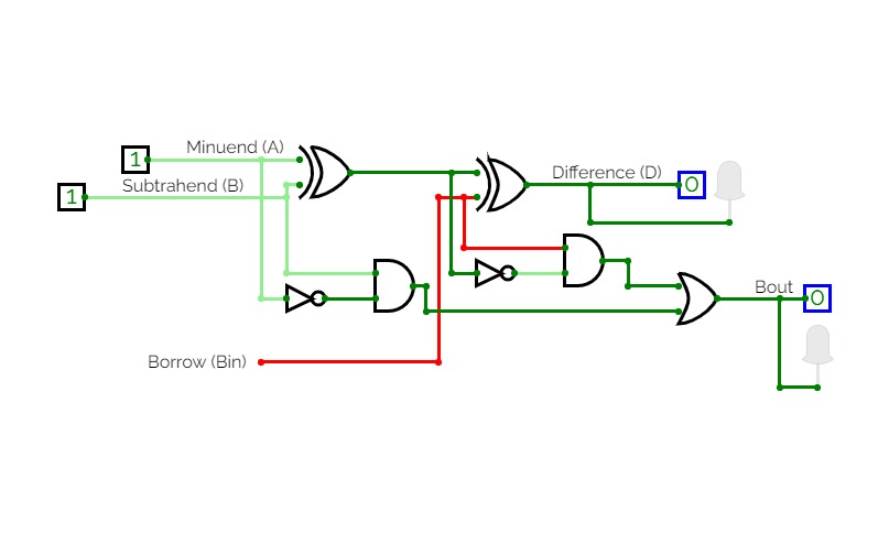
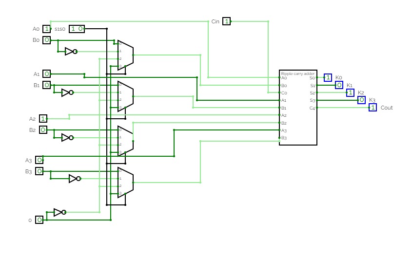
4 Bit Full Adder/SubtractorA 4-bit full adder/subtractor is a circuit that adds or subtracts two 4-bit binary numbers.
It uses a control signal to choose between addition and subtraction.
The circuit gives a 4-bit result and a carry or borrow bit.
2 bit parallel full adder.
2 bit parallel full adder.ALU
ALU1-Bit ALU
1-Bit ALUA 1-bit ALU performs basic arithmetic and logic operations on single-bit inputs.


