nand2tetrisPart1
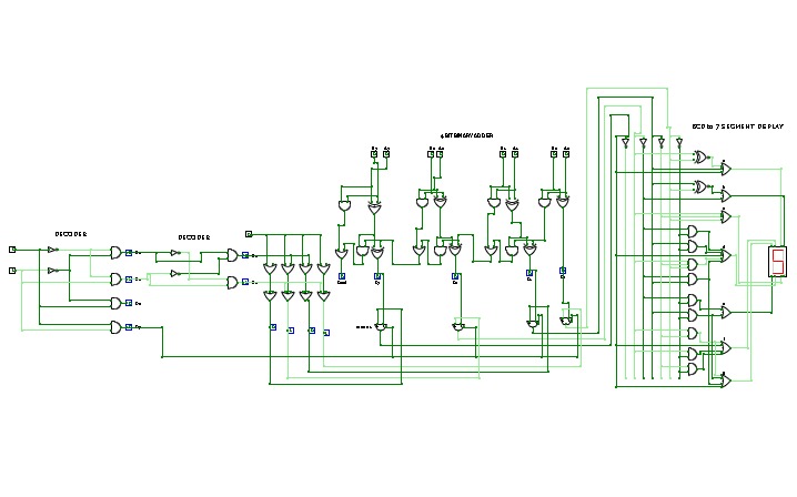
nand2tetrisPart1Logic diagrams for nand2tetris part 1 (projects 1 to 6).
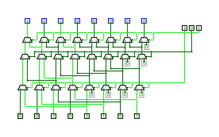
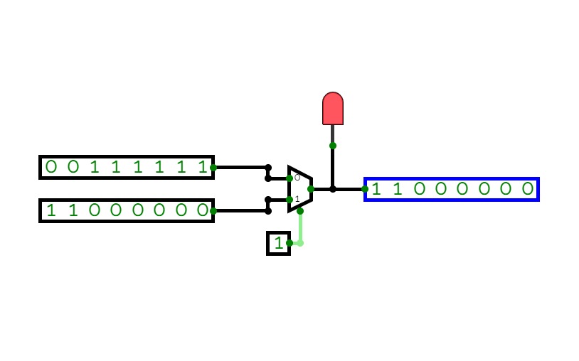
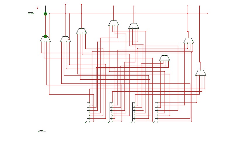
7-Bit Barrel Shifter
7-Bit Barrel ShifterCircuit to left-shift an 8-bit number by 0-7 bits! :D
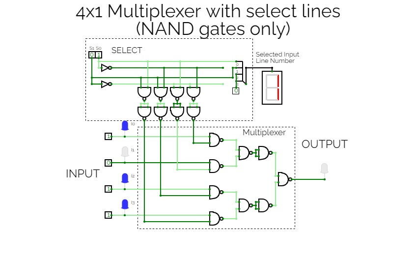
Multiplexer with NAND only
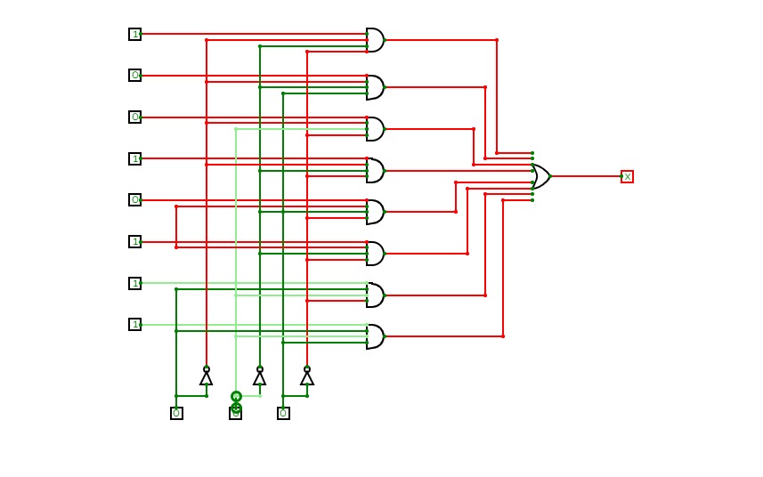
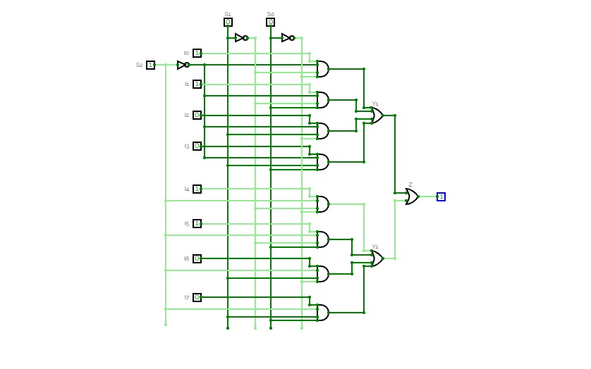
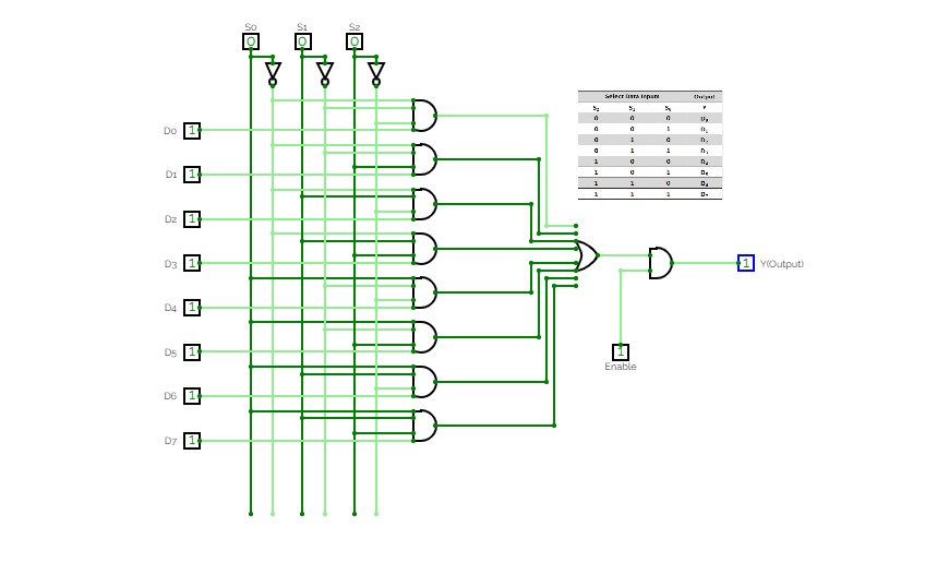
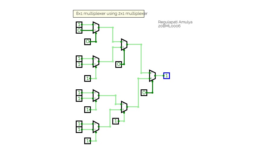
Multiplexer with NAND only8x1 Multiplexer
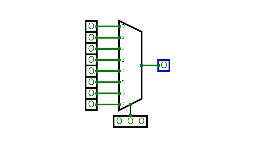
8x1 Multiplexer8x1 multiplexer has 8 data input lines I0, I1, I2, I3, I4, I5, I6, I7, 3 select lines S0, S1, S2 and one output, Y.
Truth Table for 8x1 Multiplexer
Data Select Input
Output
Y
S2
S1
S0
0
0
0
I0
0
0
1
I1
0
1
0
I2
0
1
1
I3
1
0
0
I4
1
0
1
I5
1
1
0
I6
1
1
1
I7
Multiplexer
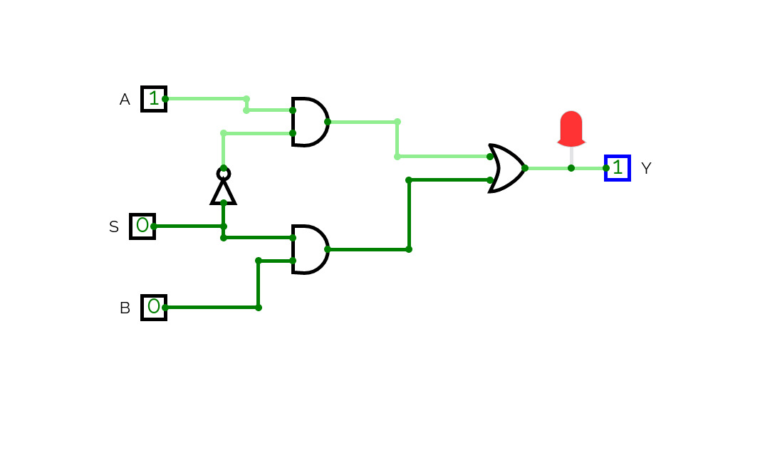
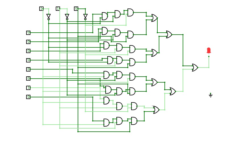
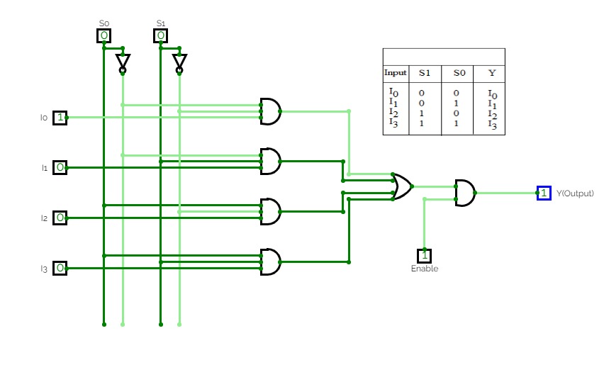
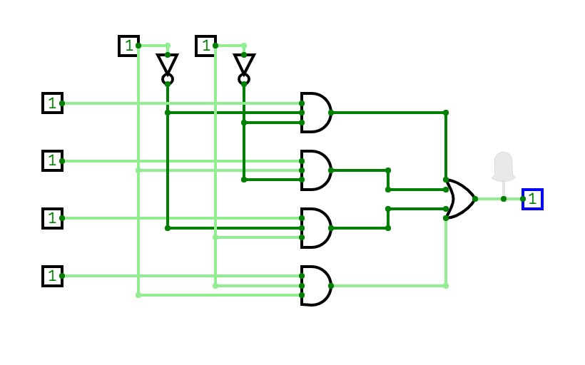
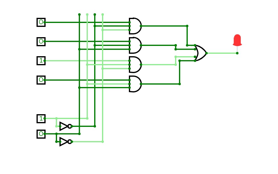
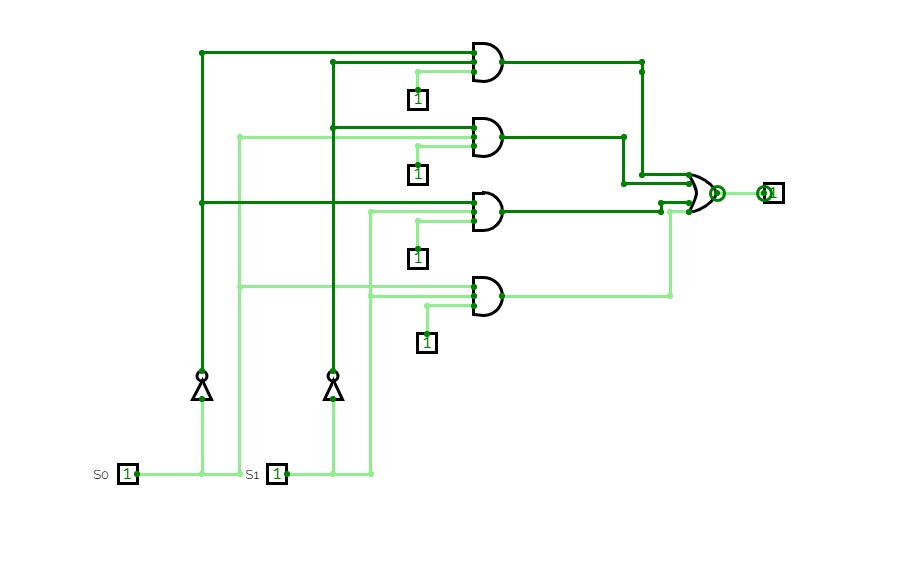
MultiplexerDesign multiplexer using basic gates,
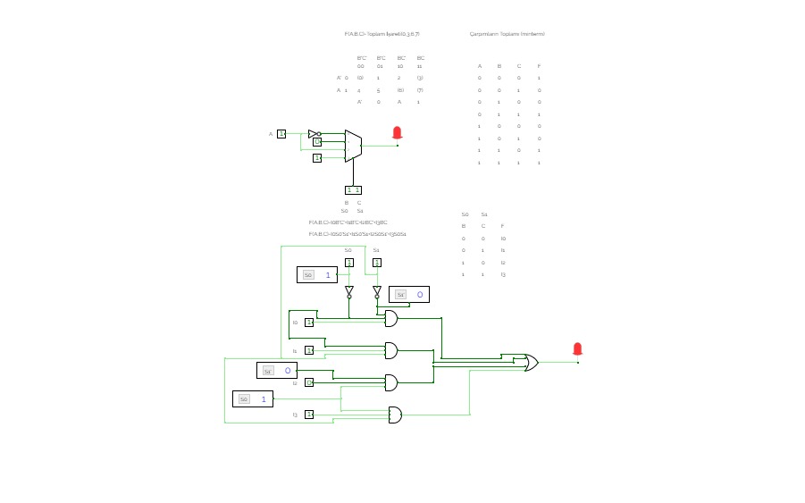
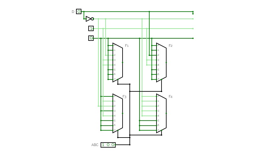
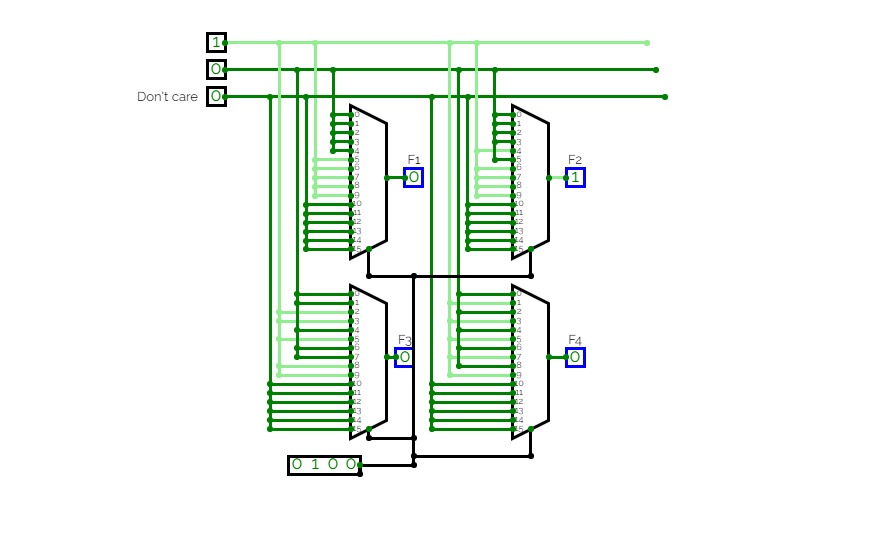
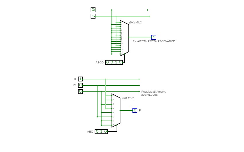
Boolean function implementation
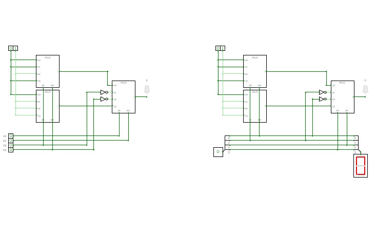
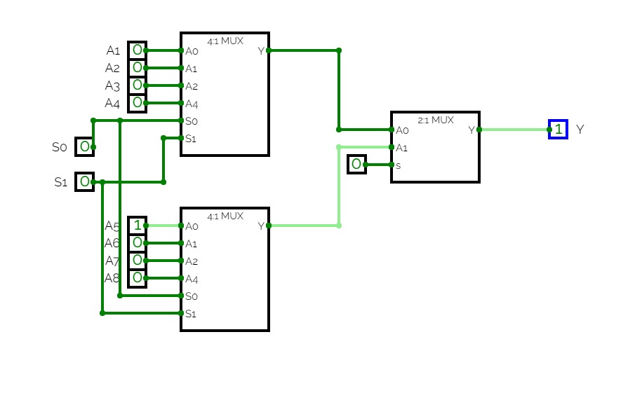
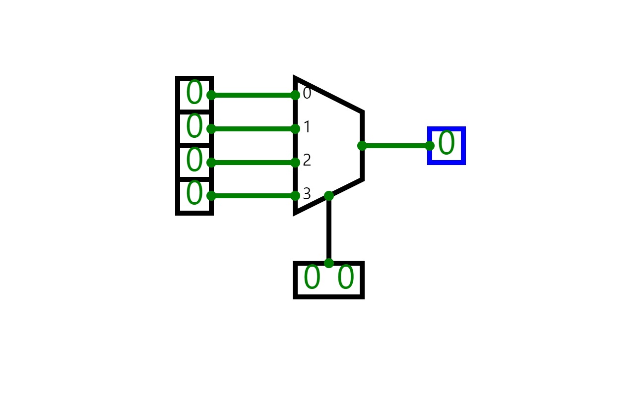
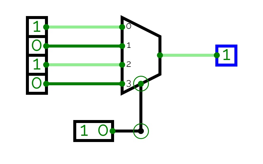
4 to 1 MUX
4 to 1 MUX8 to 1 MUX
8 to 1 MUXdcd_task3i
dcd_task3idcd_task3
Code_converter_8x1
Code_converter_8x1task3
code_converter_16x1
code_converter_16x1task3
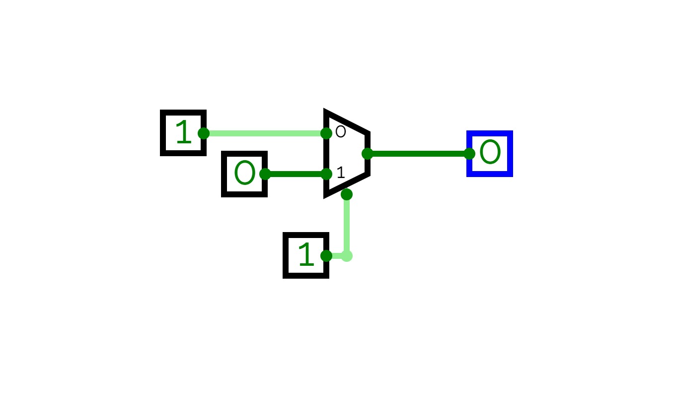
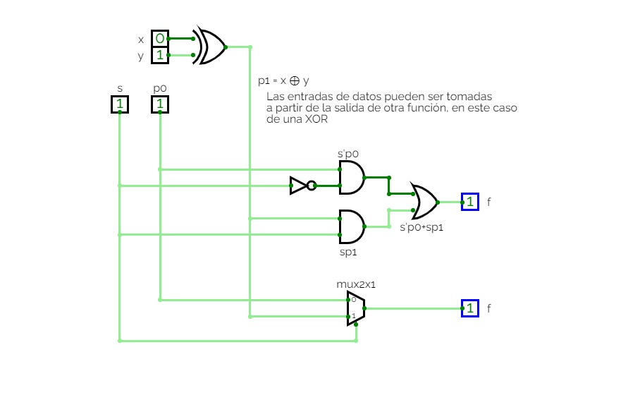
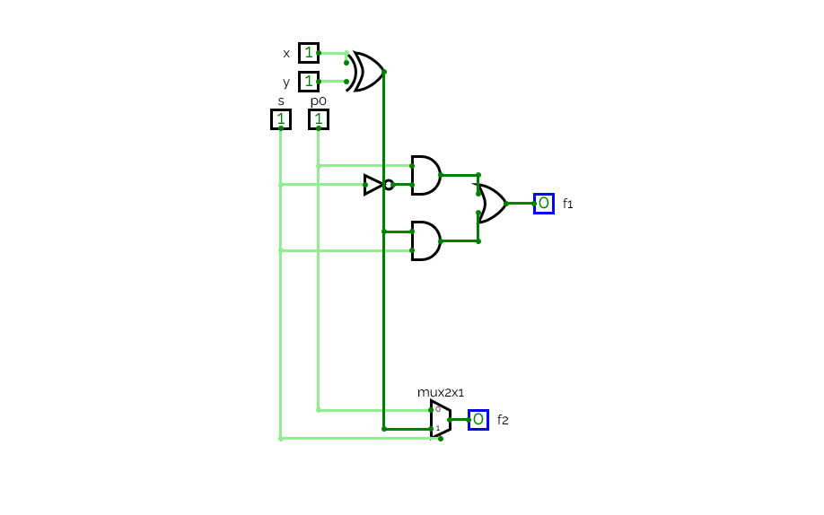
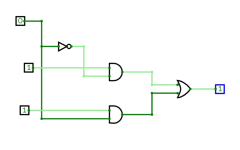
mux2×1
mux2×1Implementación de un multiplexor 2×1
mux nx1
mux nx1Implementación de un multiplexores nx1
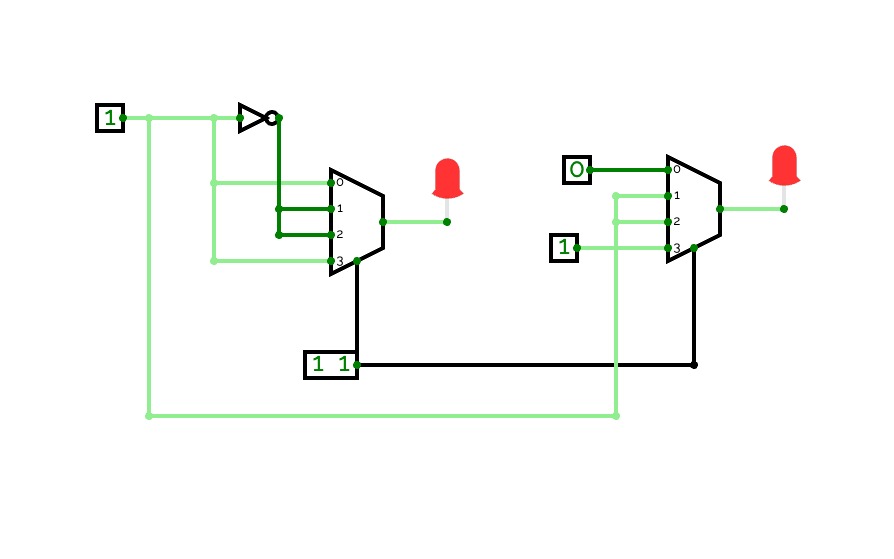
MUX 4x1
MUX 4x1multiplexador 4x1 utilizando portas logicas
Gaya gaya
Gaya gayaGroup 5 - CAO
CpE-3302
4-Bit adder with memory Control
DE Project 4:1 MUX adder
DE Project 4:1 MUX adderModule Practice
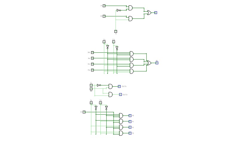
Module PracticePractice for creating and instantiating sub-circuits into a larger circuit, includes gate logic for some circuits like 2-to-1 mux and 3-to-8 decoder, as well as bit-to-bus combiner and FSM logic using T flip-flops.
decoder, mux, pipeline
decoder, mux, pipelinejust playing around with things


