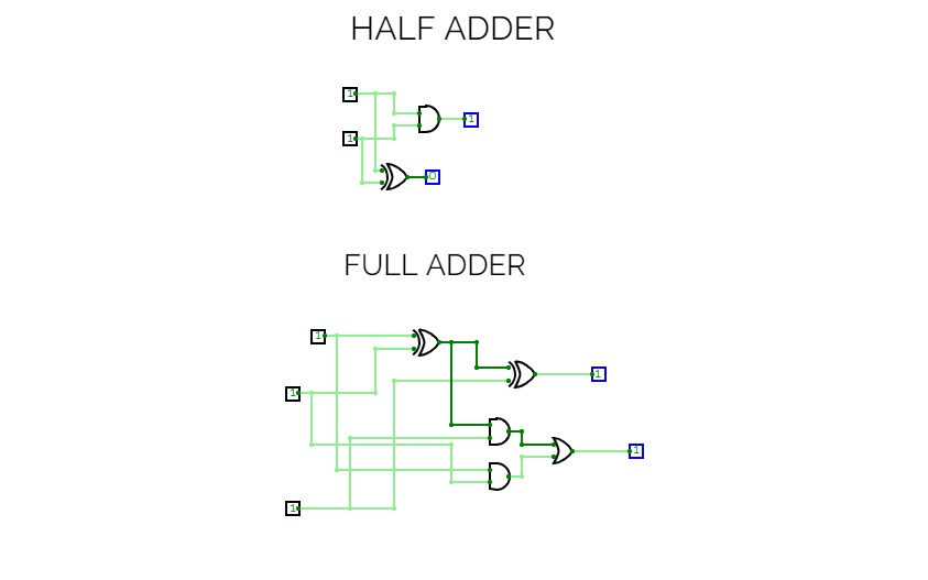
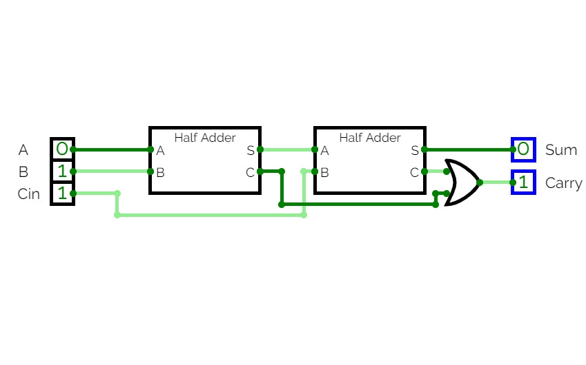
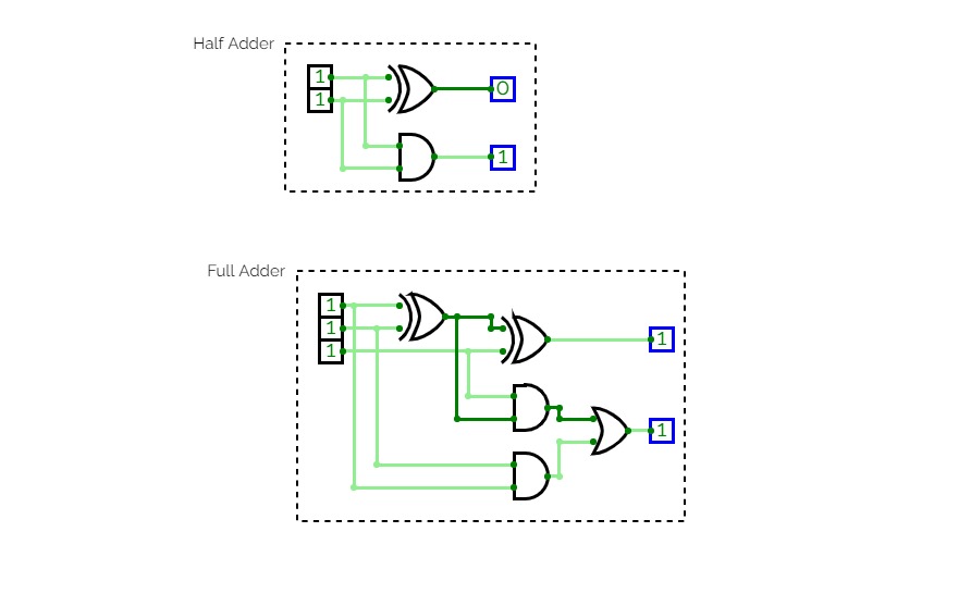
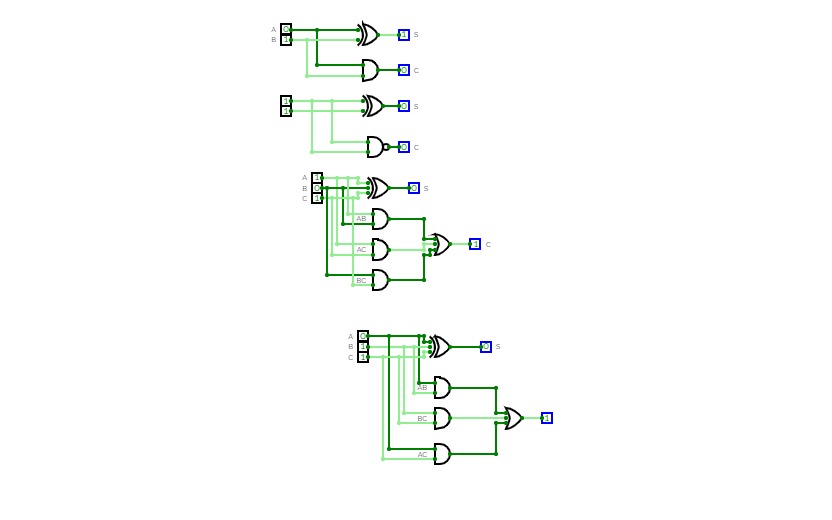
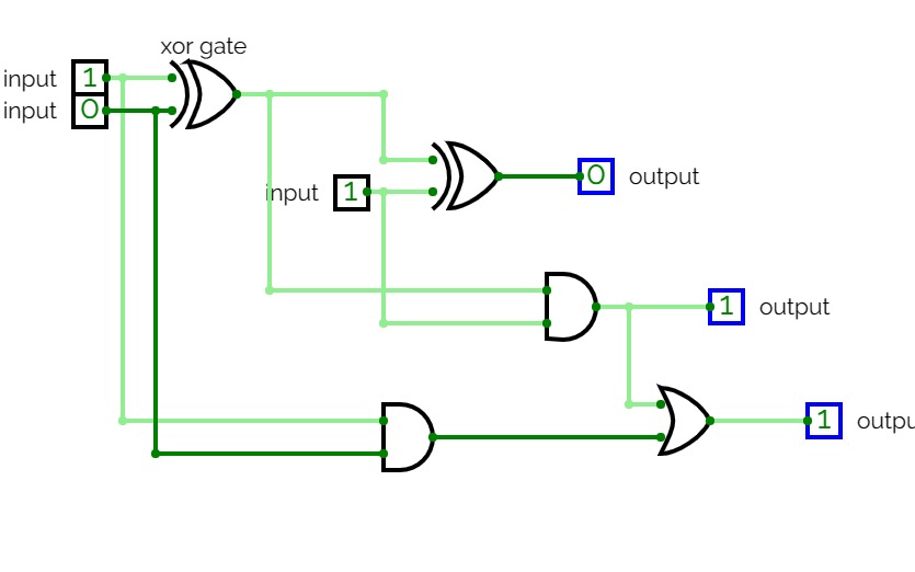
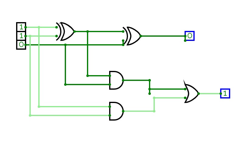
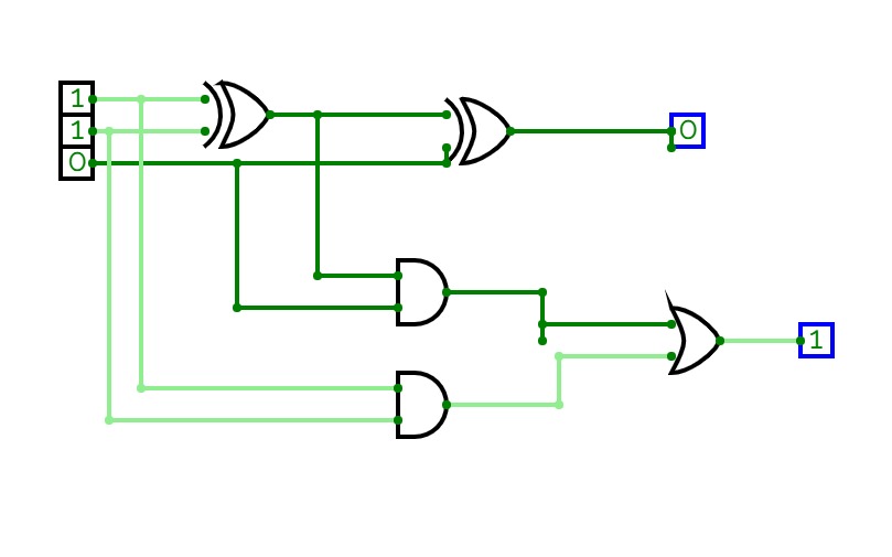
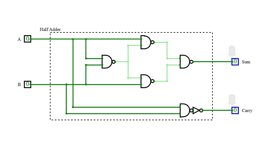
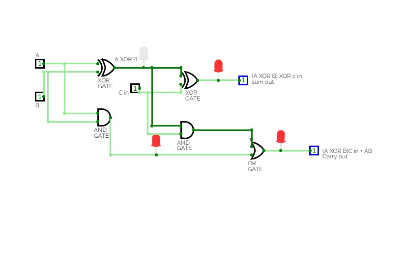
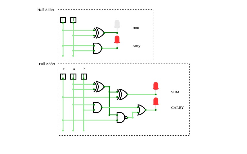
Half Adder
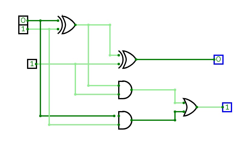
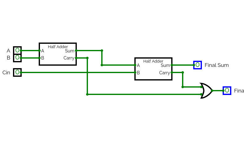
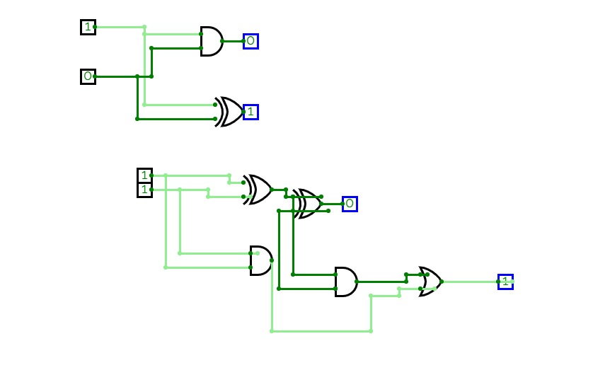
Half Adderfulladder
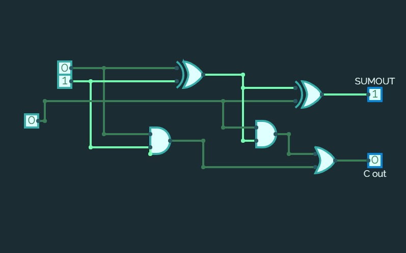
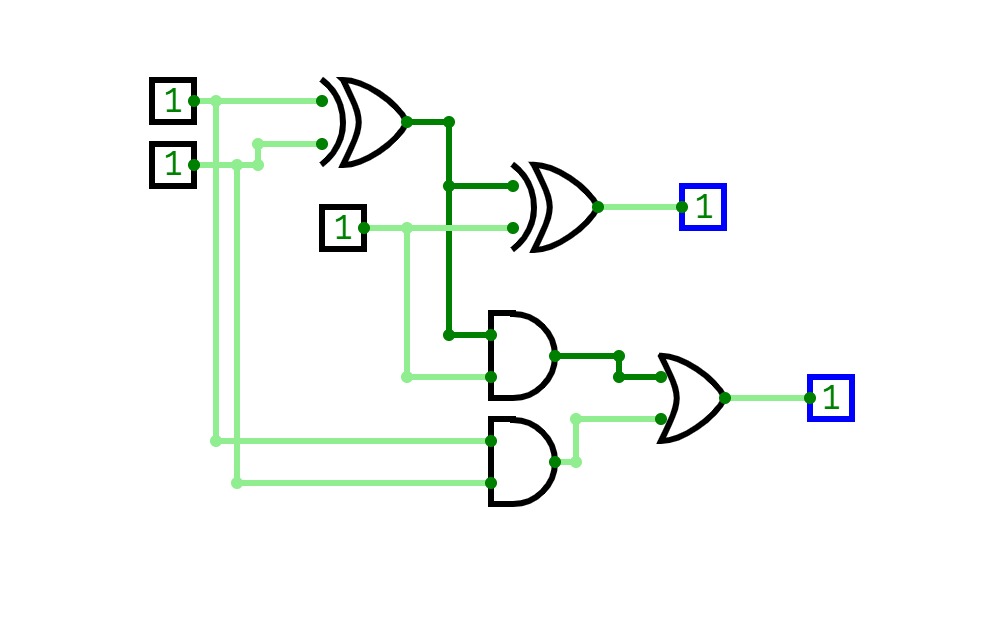
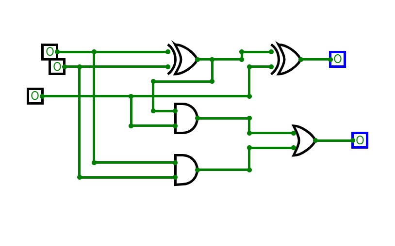
fulladderSumador completo
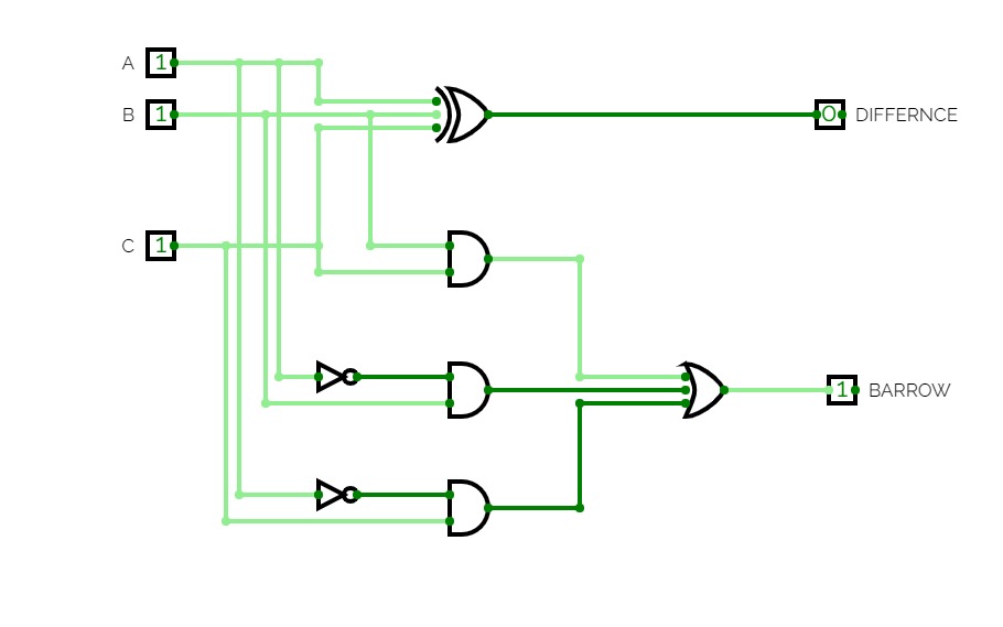
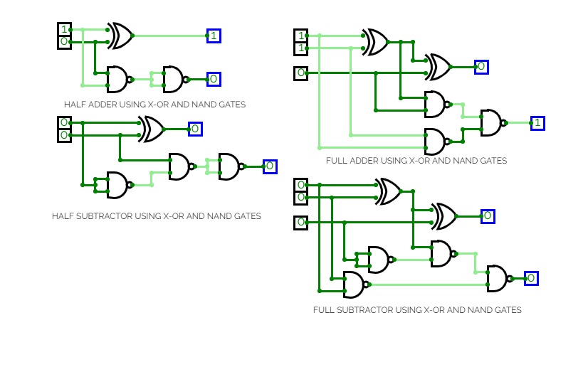
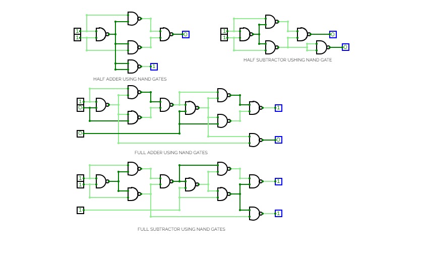
Sumador completoHalf Subtractor Part 1
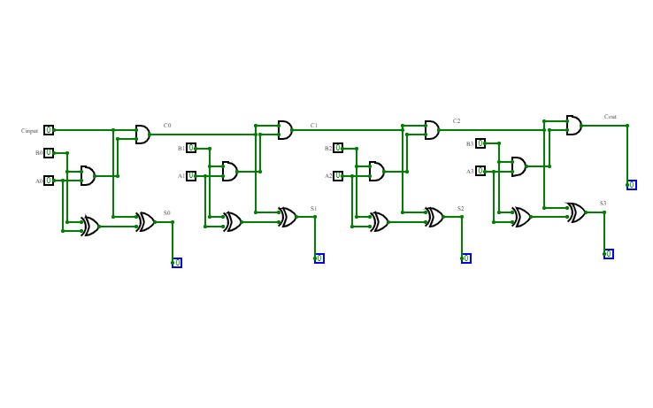
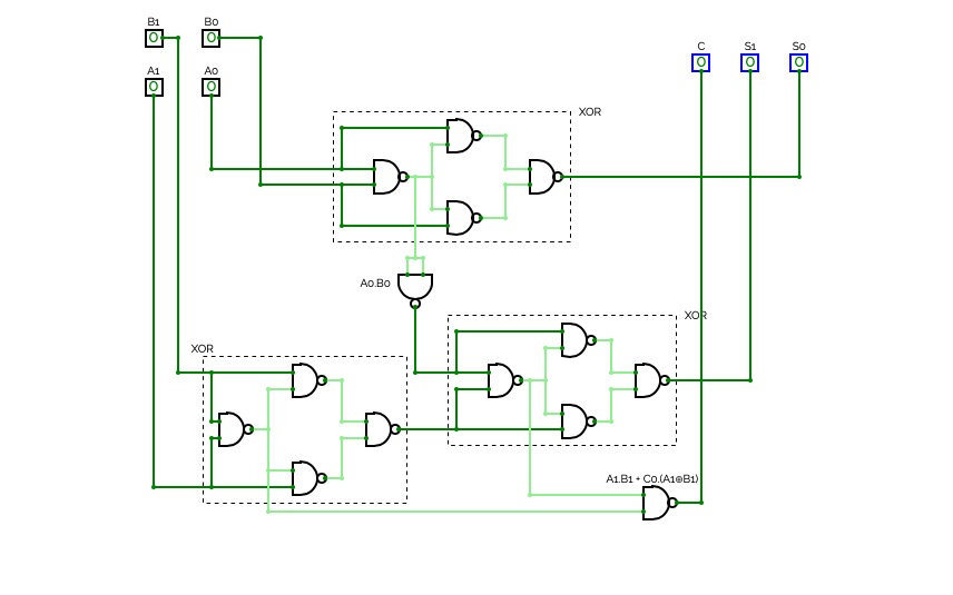
Half Subtractor Part 14-bit full adder
4-bit full addernand2tetrisPart1
nand2tetrisPart1Logic diagrams for nand2tetris part 1 (projects 1 to 6).
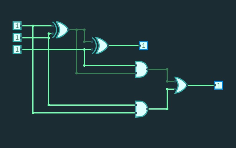
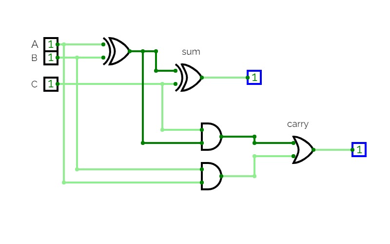
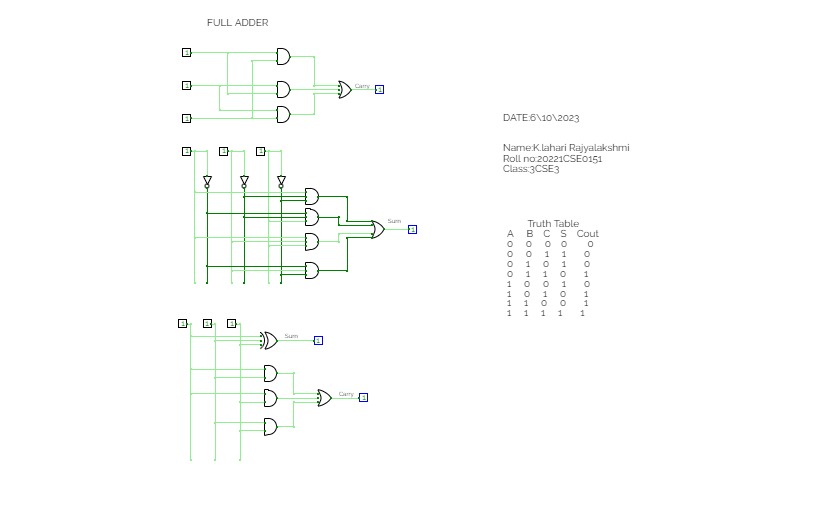
FUll Adder
FUll AdderFull adder using display
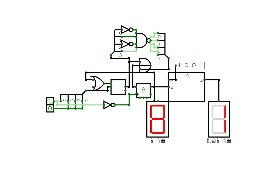
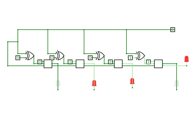
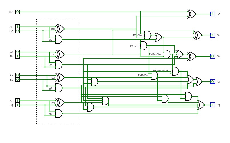
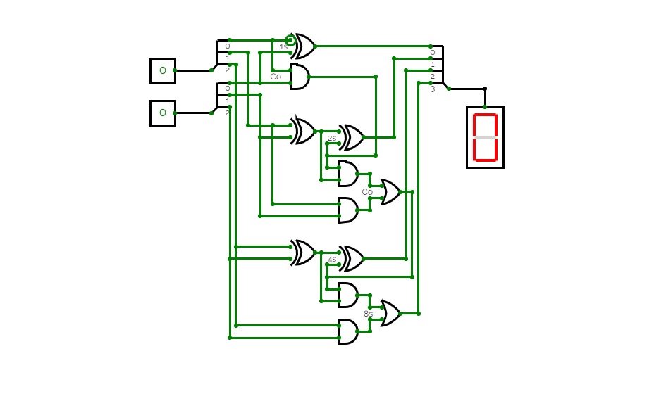
Full adder using displaythis is a four bit parallel adder. In this i used the technique of BCD adder to make this.
Since the seven segment displays are 3:8 encoders I used a custom encoder of 4:8 encoder where 4 are the sum bits and 8 are the seven segment display bits.
Making this project is very helpful in understanding the concepts of bit range overflow in the adding two binary numbers and BCD numbers.
full adder
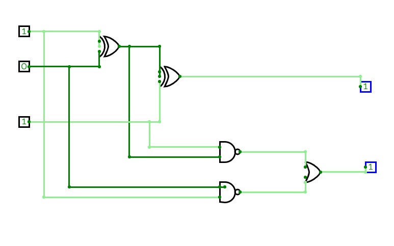
full adderFull Adder Using Basic Gates
Full Adder Using Basic GatesFull adder
Full adderExp. no. 2
Exp. no. 2full adder
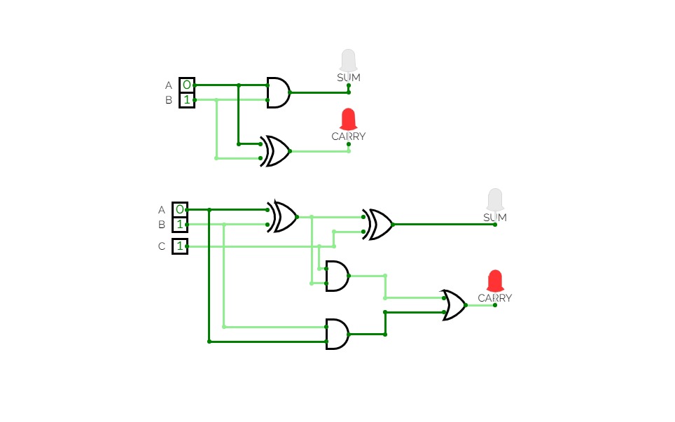
full adderfull ader and half adder
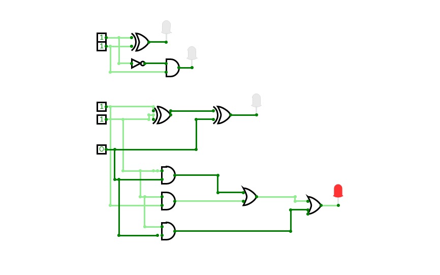
full ader and half adderFull Adder
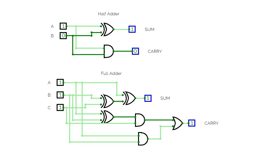
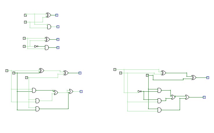
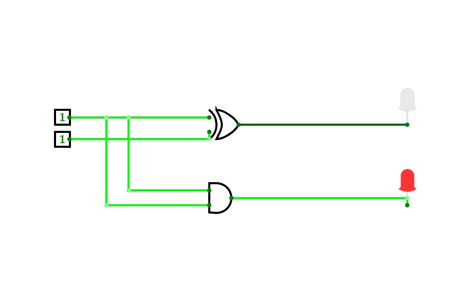
Full Adderhalf adder
half adderfull adder using logic gates
full adder using logic gatesFull adder using basic gates
Full adder using basic gatesfull adder,logic gates
full adder
full adderfa
fa9-30-20 Full Adder
9-30-20 Full AdderFull Adder
lab_1
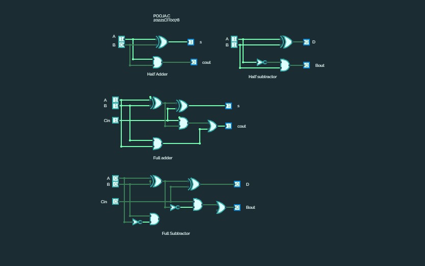
lab_1Half Subtractor and Full Subtractor
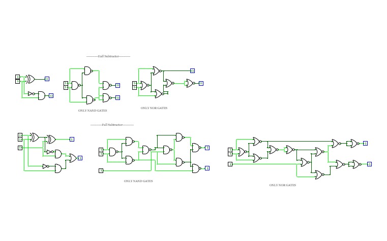
Half Subtractor and Full SubtractorConstructed Circuits using Normal gates and Universal Gates
lab 2
lab 2full adder
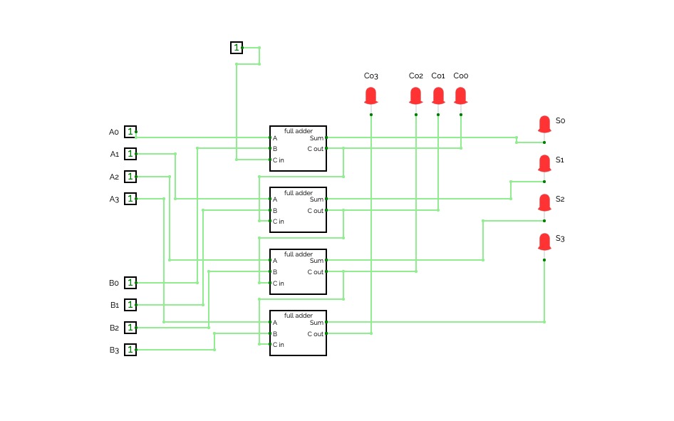
full adder4 bit full adder with carry input
4 bit full adder with carry inputstudying purpose
full adder
full adderFULL ADDER
FULL ADDERAdder Circuit
Adder CircuitPROJECT 1
PROJECT 1full adder
project 2
project 2Untitled
UntitledHalf and Fulll Adder
Half and Fulll AdderFull Adder
Full AdderFull Adder
Adder Subtractor Composit Circuit
Adder Subtractor Composit Circuitlogic gates
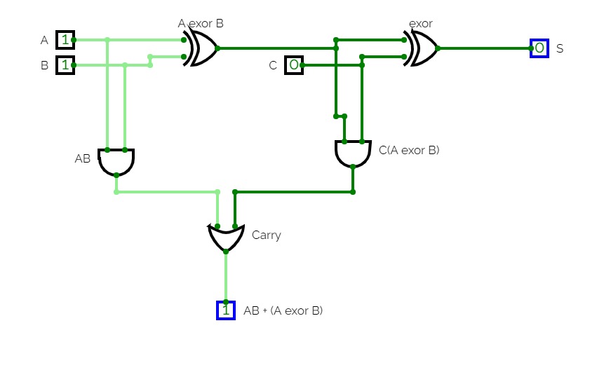
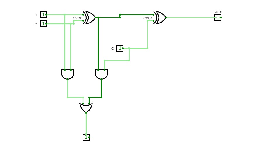
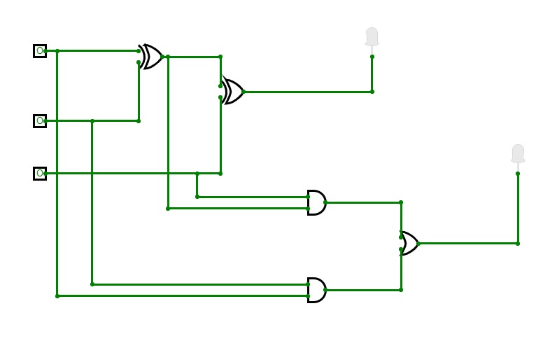
logic gatesfull adder using basic gates
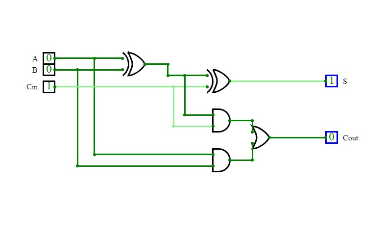
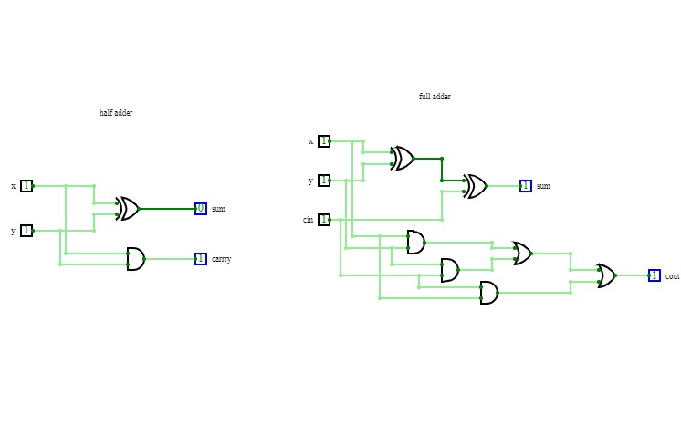
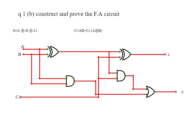
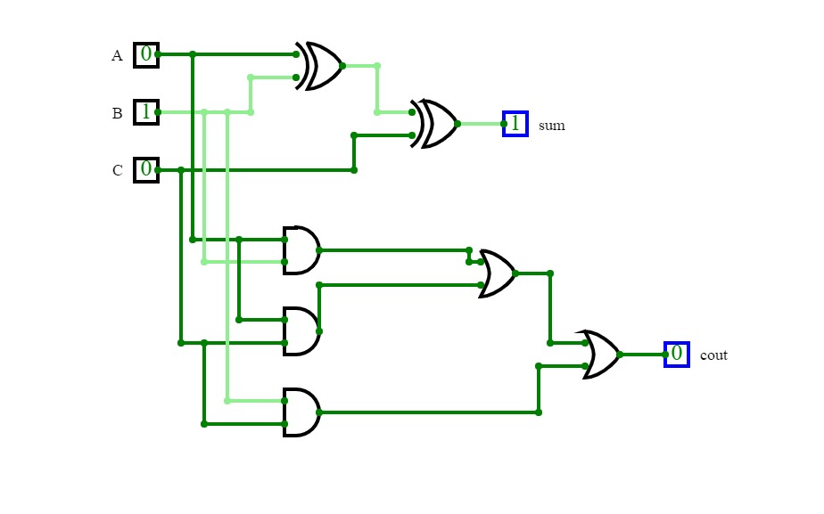
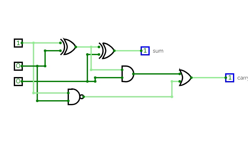
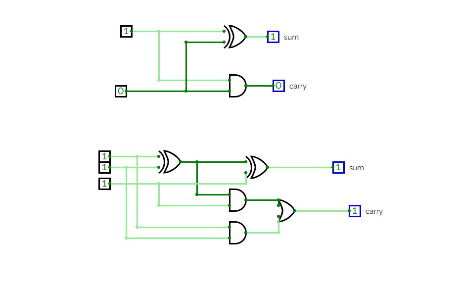
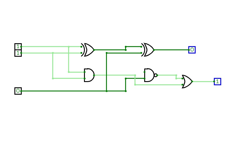
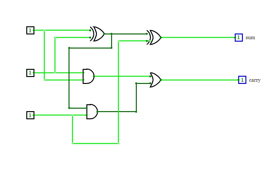
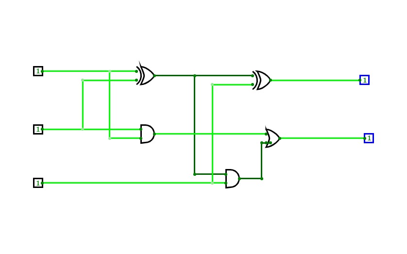
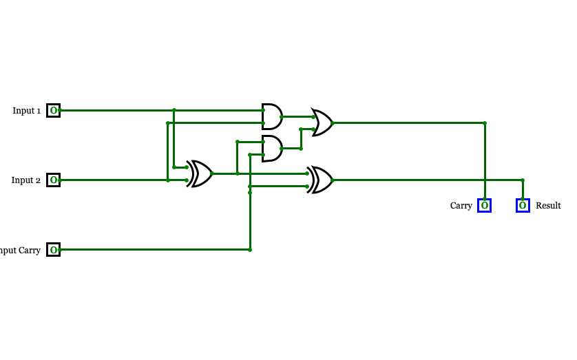
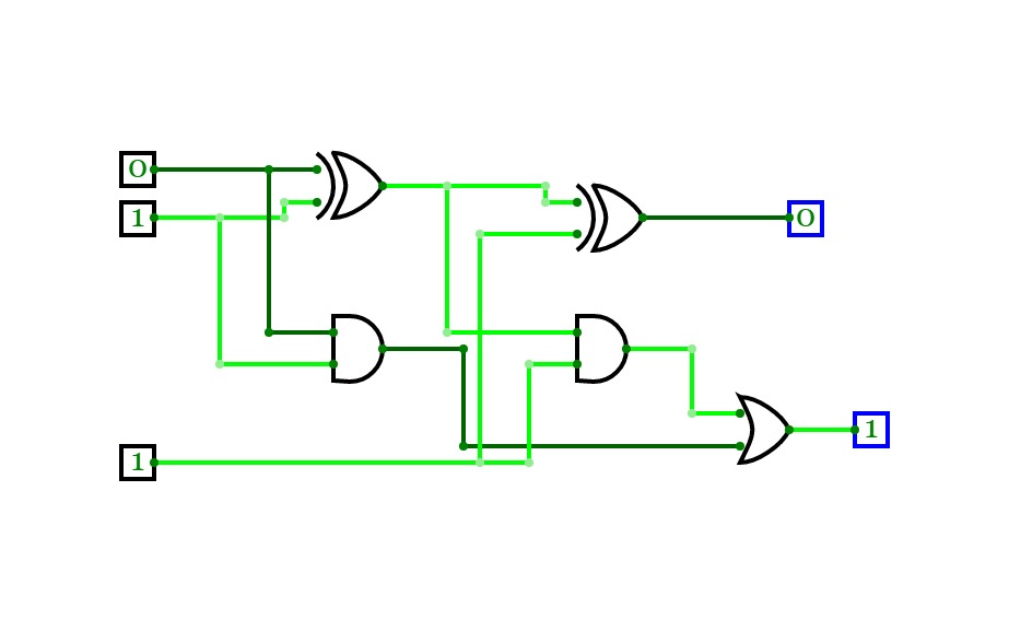
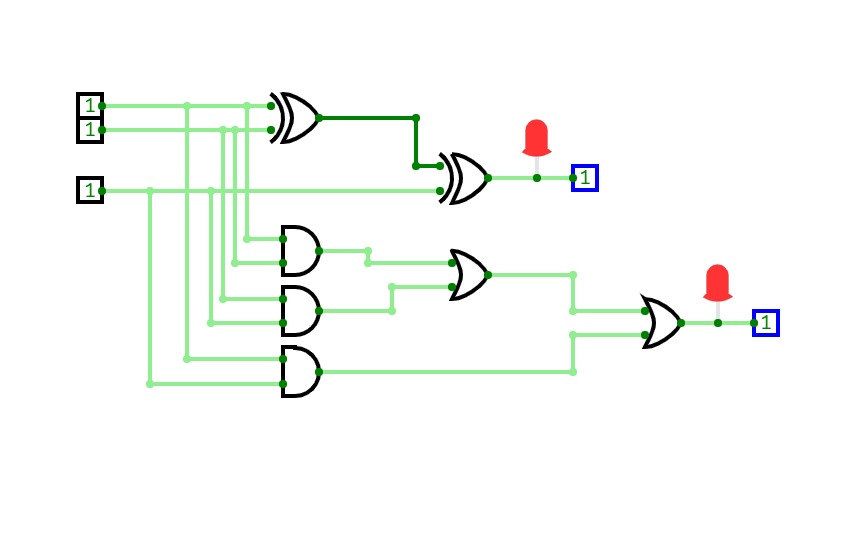
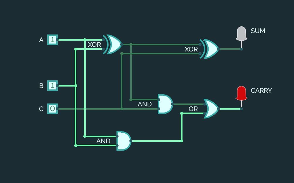
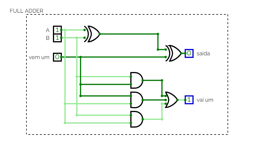
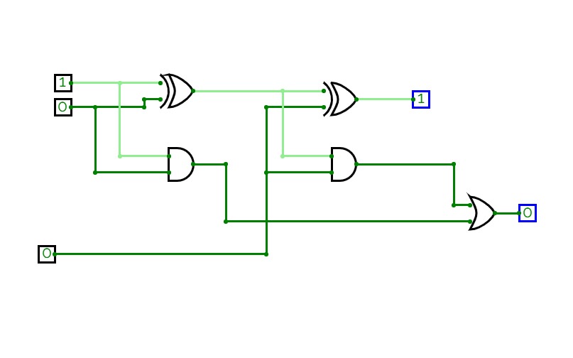
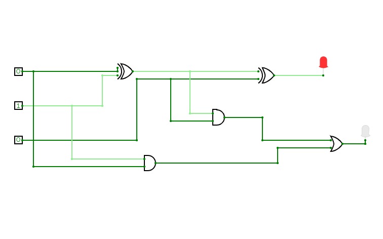
full adder using basic gatesThis is a full adder circuit using or,and gates.
Full Adder
Full AdderTwo 3-bit number Adder
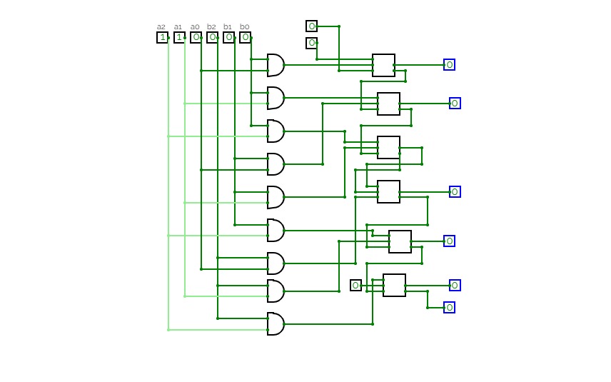
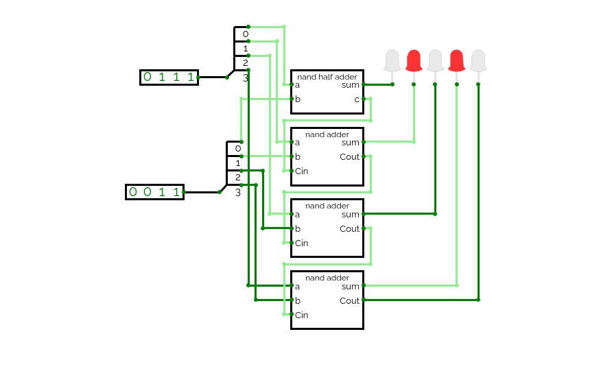
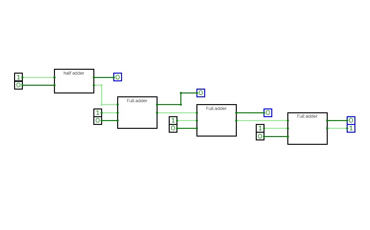
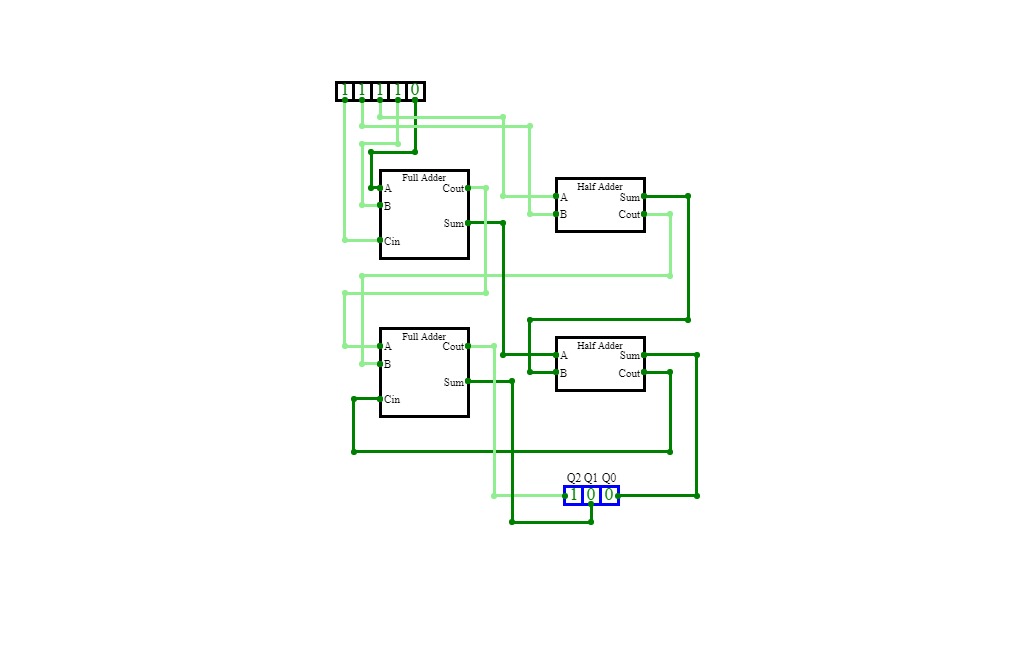
Two 3-bit number AdderA circuit that adds two 3-bit numbers using a half-adder and a full-adder.
A circuit that takes two decimal numbers A and B as input and then splits in into their corresponding three bits using a splitter and then calculates their summation using XOR, AND and OR gates. This generates 4 output lines for 4 bits of the summation, and a reversed splitter is finally used to join the output lines to produce a 4-bit output and displayed using a Hex-Display.
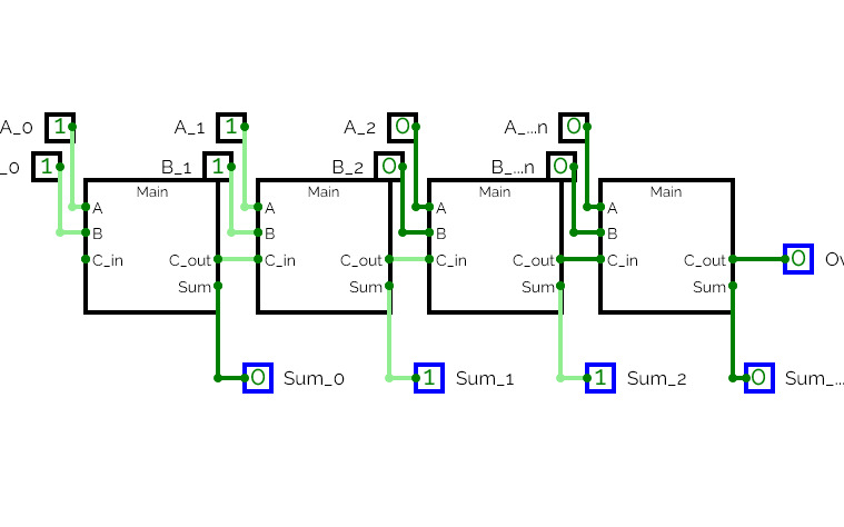
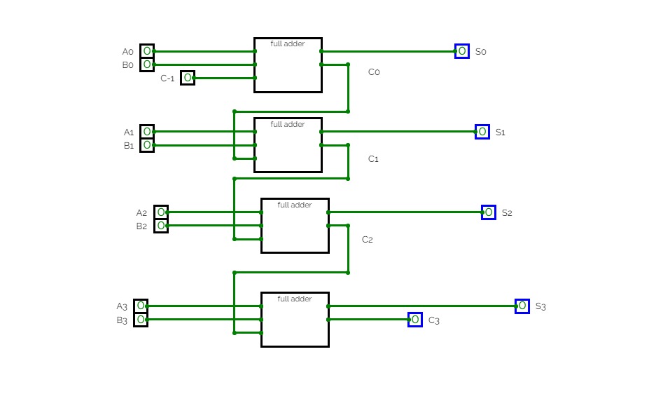
This is a ripple-carry adder.
adder circuits
adder circuitsfull adder circuit simulation
full adder circuit simulationfull adder
full adderfull adder
full adderFull Adder
Full AdderUntitled
Untitled科技應用專題109-2
科技應用專題109-2full adder
full adderfull adder using mux
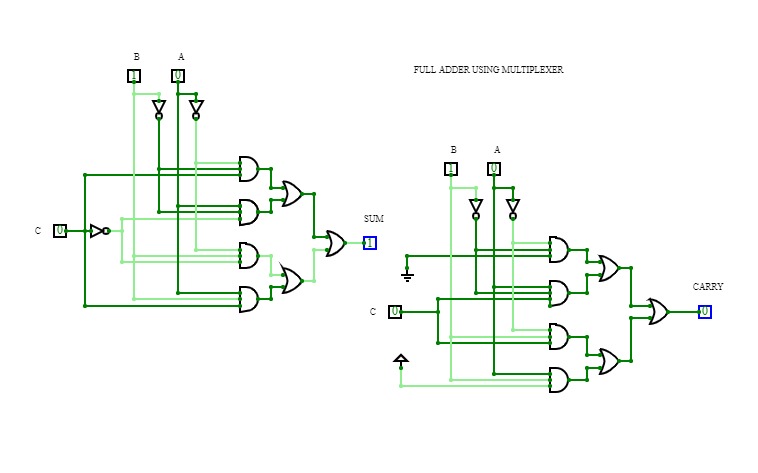
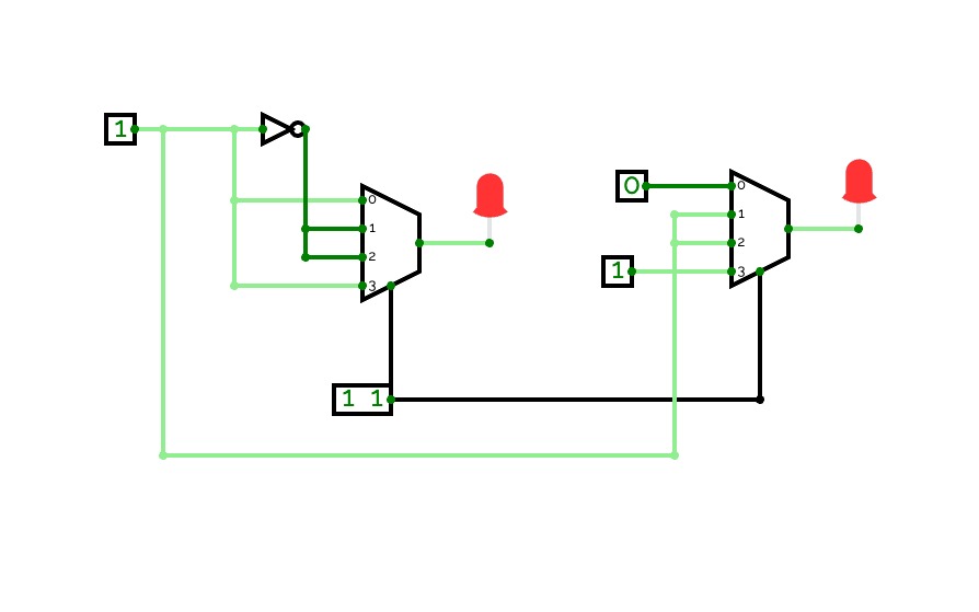
full adder using muxIt is a full adder circuit made using multiplexer from basic gates.
PRIYA
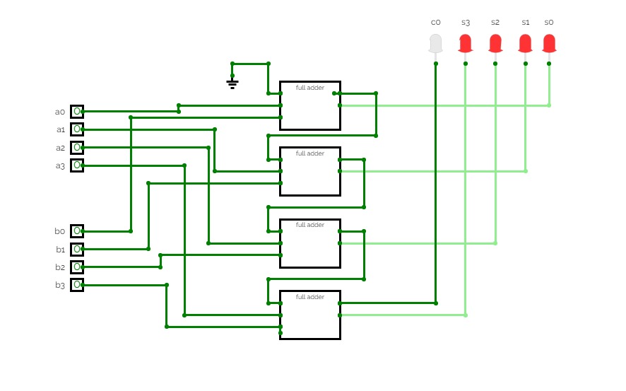
PRIYA4-bit full adder
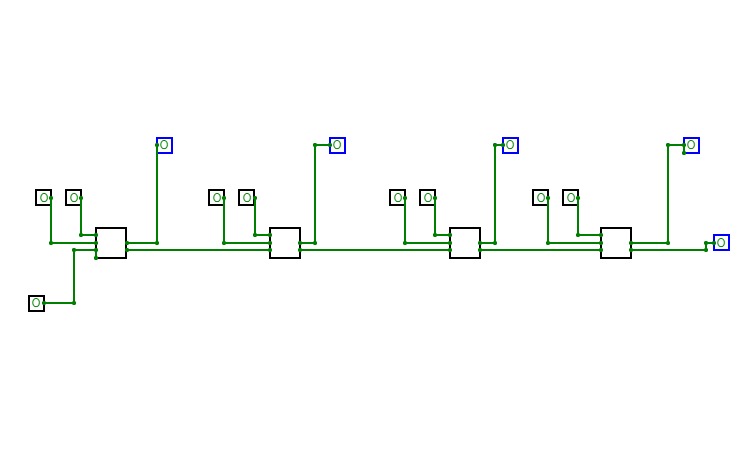
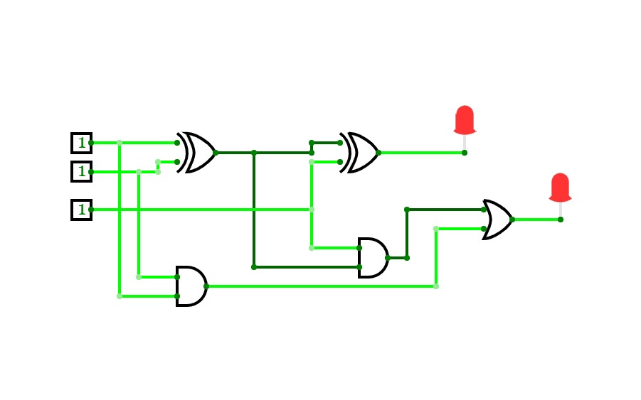
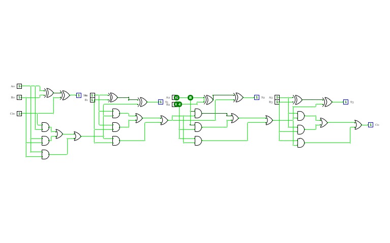
4-bit full adderI'm a beginner, and this is my first circuit. it is 4-bit full adder, which is used to add 3 4-bit input and producing 4-bit or 5-bit output. it is implemented by using XOR gate, AND gate, and OR gate.
Full adder
Full addershubhankar
shubhankarLab 4
Lab 4LAB2
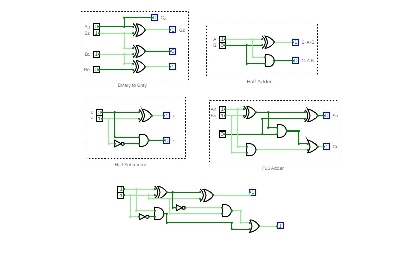
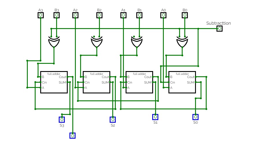
LAB2binary to gray/ adder subtractor
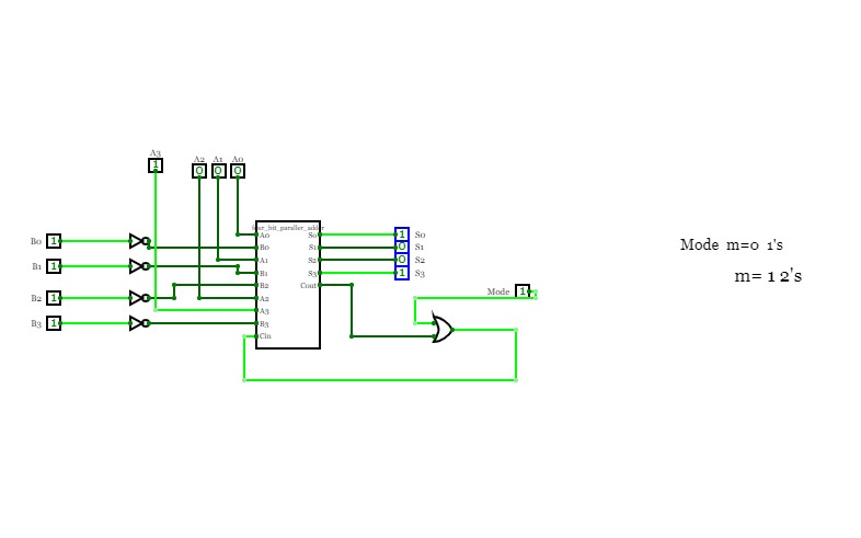
binary to gray/ adder subtractor4bit adder subtractor
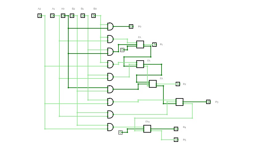
4bit adder subtractorbinary multiplier
binary multiplierbinary multiplier
binary multiplierhalf adder and full adder
half adder and full adder.
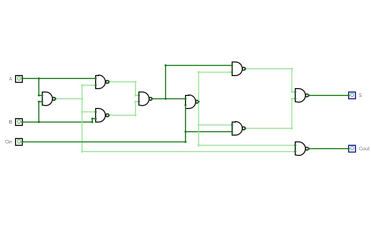
Full adder (NAND gate)
Full adder (NAND gate)Q1 (B)
Q1 (B)full adder
full adderfull adder
full adderfull adder
half adder and full adder
half adder and full adder21bds0194
21bds0194bittaraj roy
bittaraj royshiv full adder
shiv full adderproject2
project2PROJECT 2
PROJECT 2full adder madhur
full adder madhurfull adder
full adderfull adder
full adderdigital electronic lab
digital electronic labnand adder
nand adderproject 2
project 2Full adder using half adder
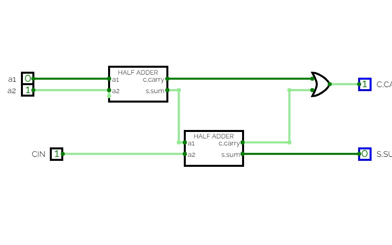
Full adder using half adderThis is full adder using half adder. Here even truth table is given for your conveniency.
Program 2 - Half and Full adder
Program 2 - Half and Full adderHalf adder and full adder circuit
full adder
full adderfull adder
full adder
full adderfull adder
Qasim (bscs22f020)
Qasim (bscs22f020)experiment 2 level2
experiment 2 level2experiment 2 level3
experiment 2 level3project 1.gates
project 1.gates0675 FULL ADDER
0675 FULL ADDERSanket Londhe
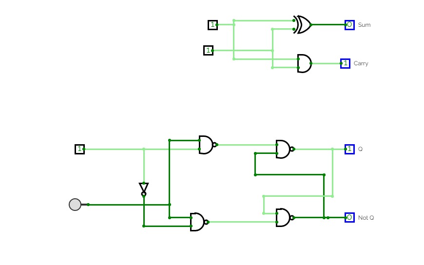
Sanket LondheHALF ADDER using logic gates
HALF ADDER using logic gatesfull adder
full adderexp-2_2200290110060.pdf
exp-2_2200290110060.pdffull adder logic gate
full adder logic gateshubham verma
shubham vermaUntitled
Untitledteam baka
team bakafull adder
full adderUntitled
Untitled
Untitled
UntitledHritik
HritikHritik
HritikUntitled
Untitledn bit paraller adder
n bit paraller adderCount 1s
Count 1sBased of full adder and half adder circuit, build a circuit that count 1s of input.
DE Project 4:1 MUX adder
DE Project 4:1 MUX adderhalf and full adder
half and full addermy projects
my projectsfull adder
full adderSubCircuits
SubCircuitsUntitled
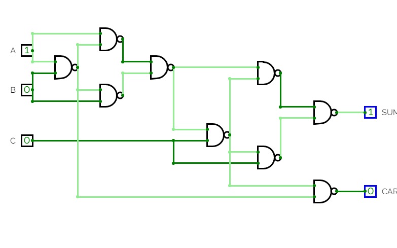
UntitledFull adder using nand gate
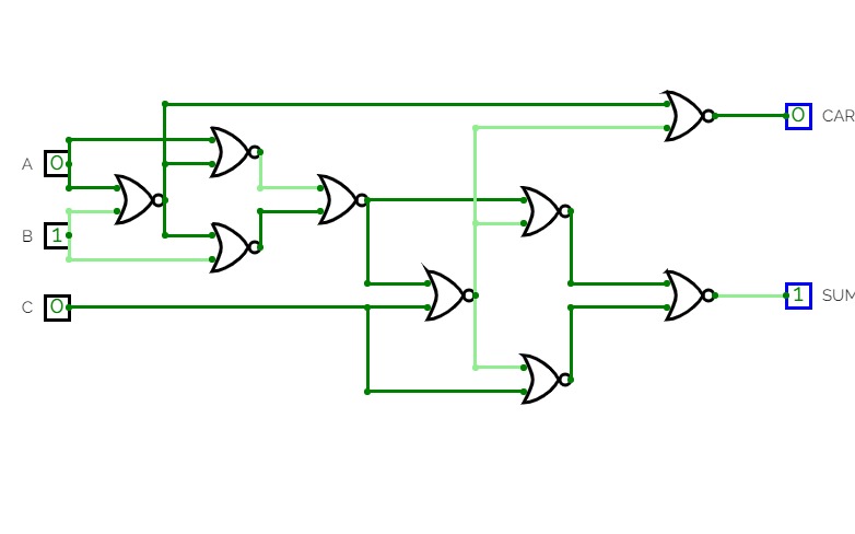
Full adder using nand gateFull adder using NOR gate.
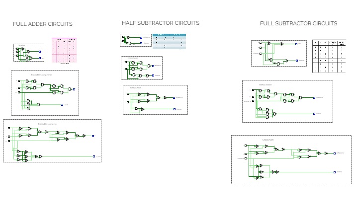
Full adder using NOR gate.full adder , half subtractor , full subtractor using nand and nor
full adder , half subtractor , full subtractor using nand and norRoom 7
Room 7Untitled
UntitledAdders
Addersexp 4
exp 4trinadh done by project





.png)
