

Half Adder
Half AdderHalf Subtractor Part 1
Half Subtractor Part 1khushi gupta IIT2019141
khushi gupta IIT2019141nand2tetrisPart1
nand2tetrisPart1Logic diagrams for nand2tetris part 1 (projects 1 to 6).
Half Adder
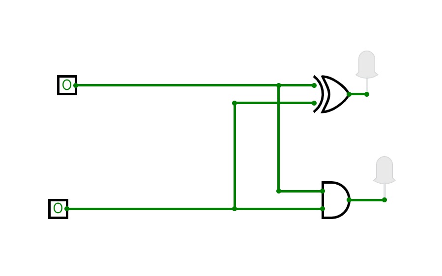
Half AdderThis is a test project to understand how the combinational analysis tool works.
half adder
half adderhalf adder using basic gates
half adder using basic gateslab 1
lab 1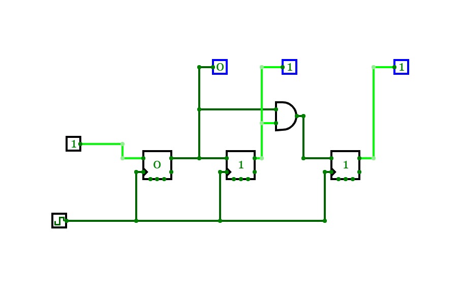
practical2
practical2half adder useing xor and nand gate
Exp. no. 2
Exp. no. 2
half adder
half adder
experiment 2
experiment 2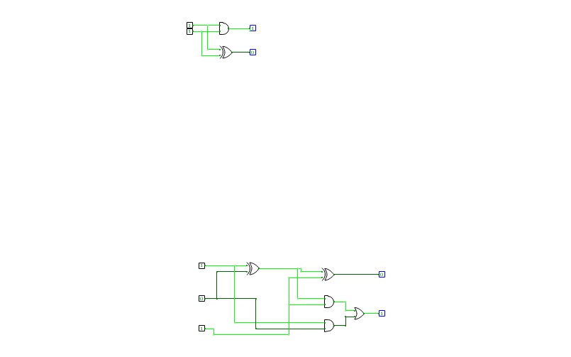
full ader and half adder
full ader and half adder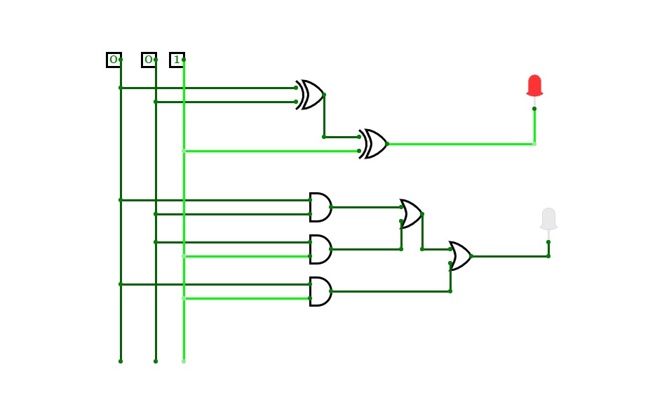
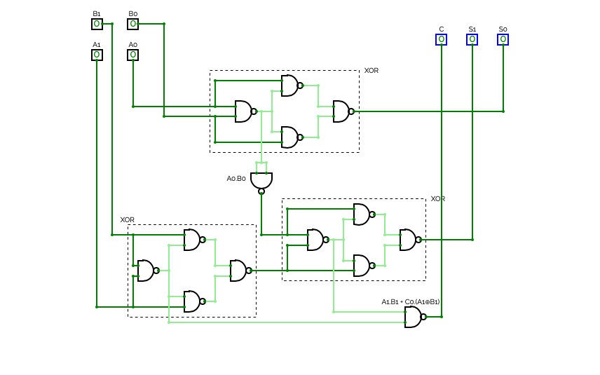
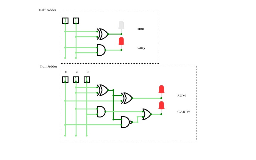
Full Adder
Full Adder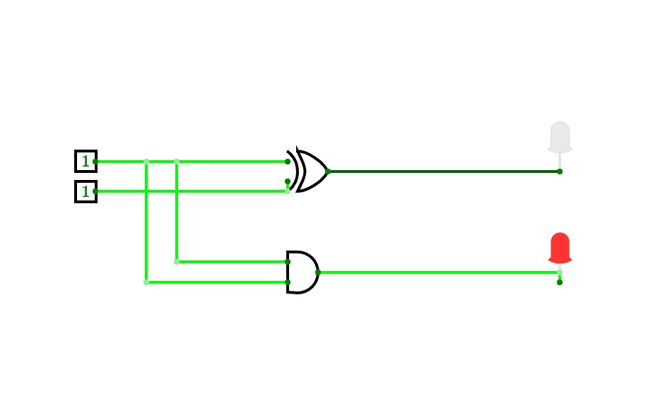
half adder
half adder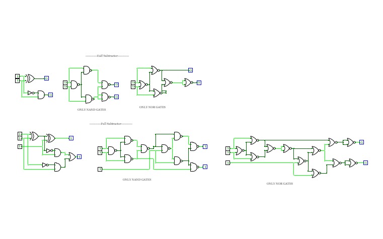
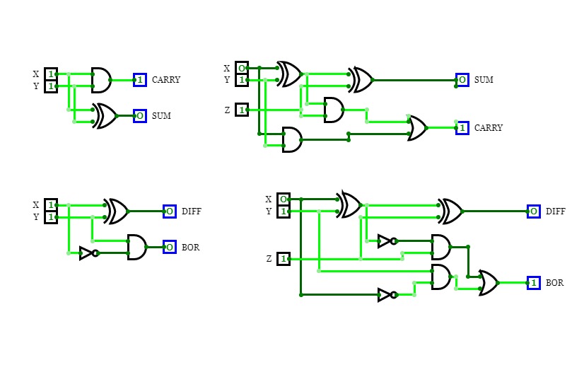
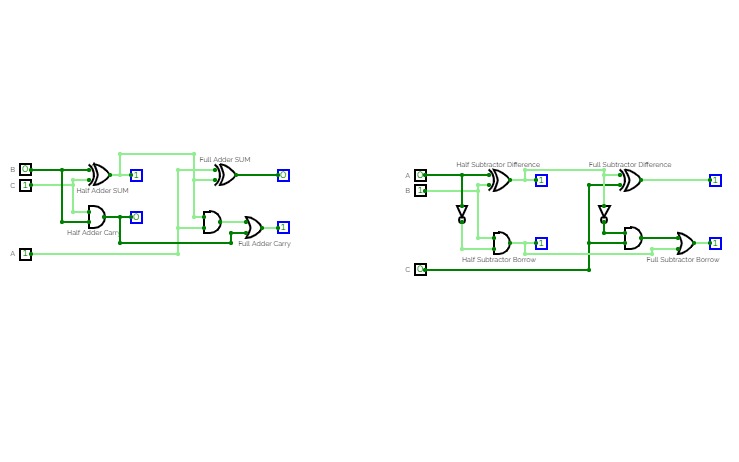
Half Subtractor and Full Subtractor
Half Subtractor and Full SubtractorConstructed Circuits using Normal gates and Universal Gates
Adder Circuit
Adder Circuit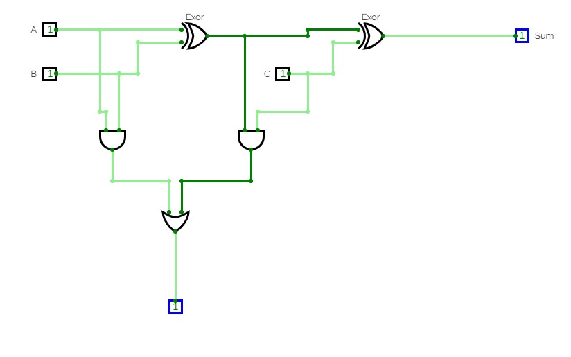
Project-1
Project-1halfadder
full adder
full adder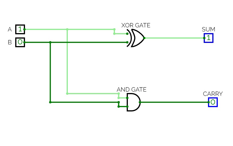

project 2
project 2to varify half adder
Project-1
Project-1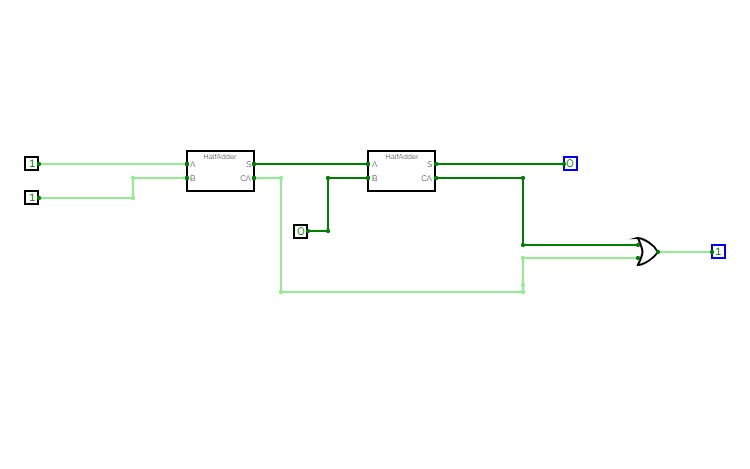
MCALab
MCALabHalf adder

Adder and Subtractor
Adder and Subtractor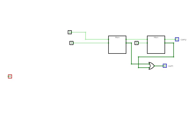
mca 2020 to 2022
mca 2020 to 2022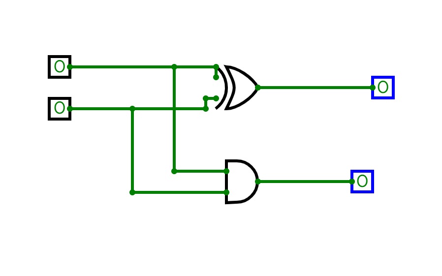
mca 1
mca 1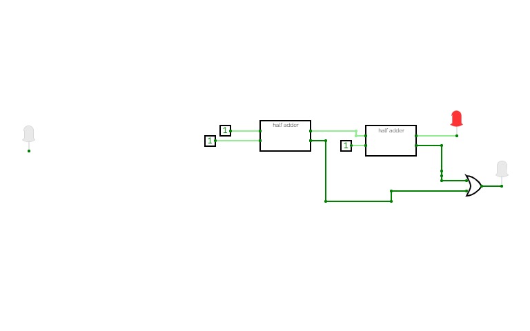
mca1
mca1circuit is half adder
mca 1
mca 1this gate is half adder
Half and Fulll Adder
Half and Fulll Adder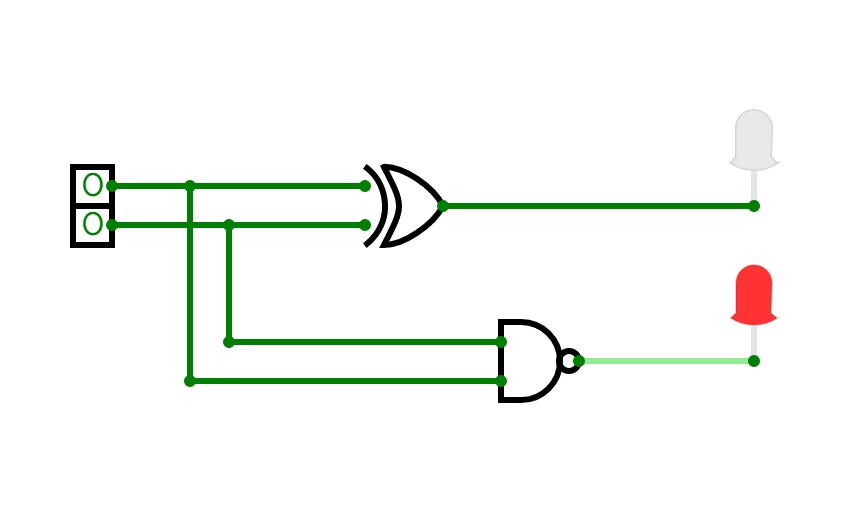
half adder
half adder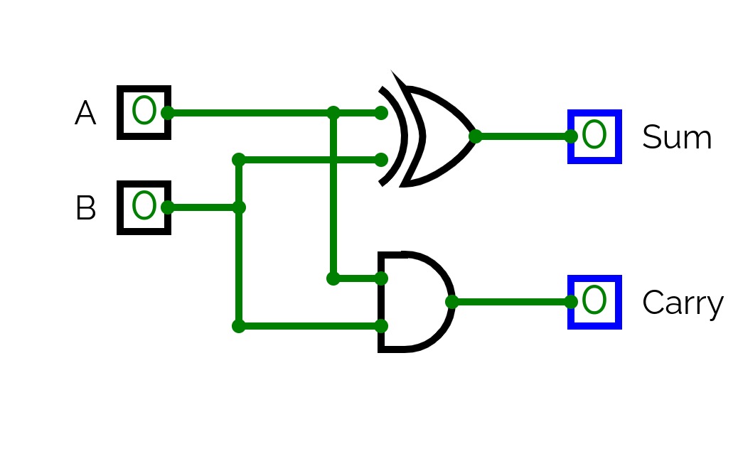
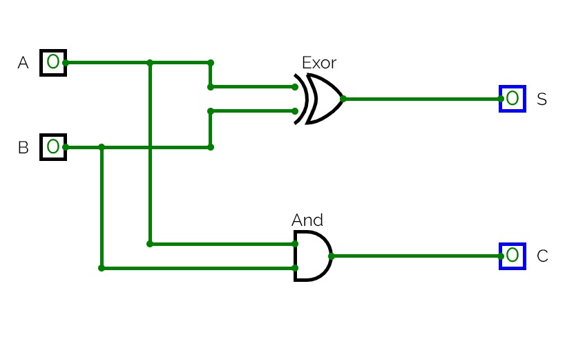
Adder circuits
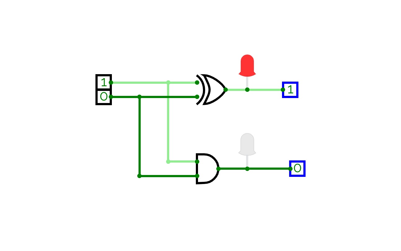
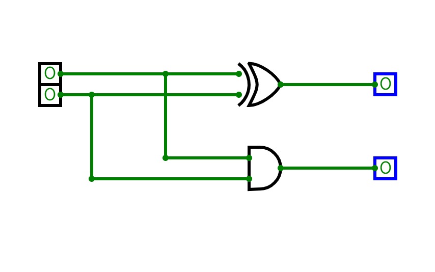
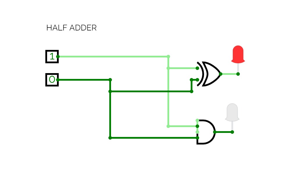
Adder circuitsThis is an half adder circuit, it takes two one bit binary digits and adds them to produce a sum bit and a carry bit, however this circuit is incapable of adding more than one bit binary digit hence it is known as the binary half adder
Projects
Projects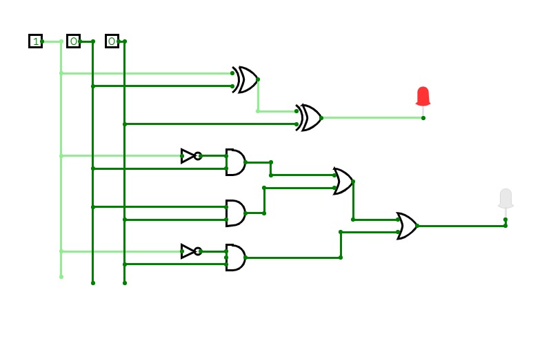
full adder
full adder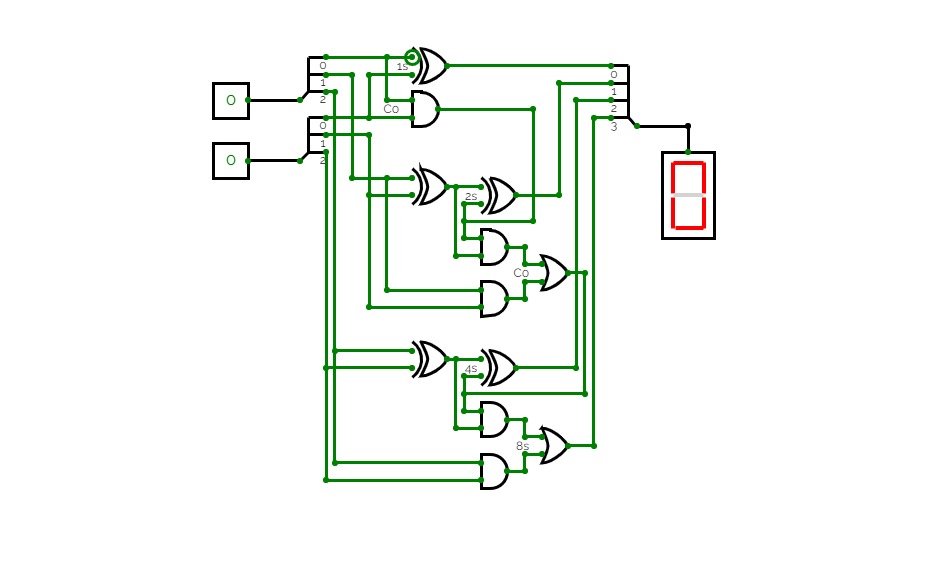
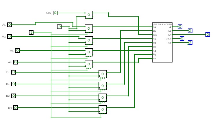
Two 3-bit number Adder
Two 3-bit number AdderA circuit that adds two 3-bit numbers using a half-adder and a full-adder.
A circuit that takes two decimal numbers A and B as input and then splits in into their corresponding three bits using a splitter and then calculates their summation using XOR, AND and OR gates. This generates 4 output lines for 4 bits of the summation, and a reversed splitter is finally used to join the output lines to produce a 4-bit output and displayed using a Hex-Display.
This is a ripple-carry adder.
Adder circuits
Adder circuits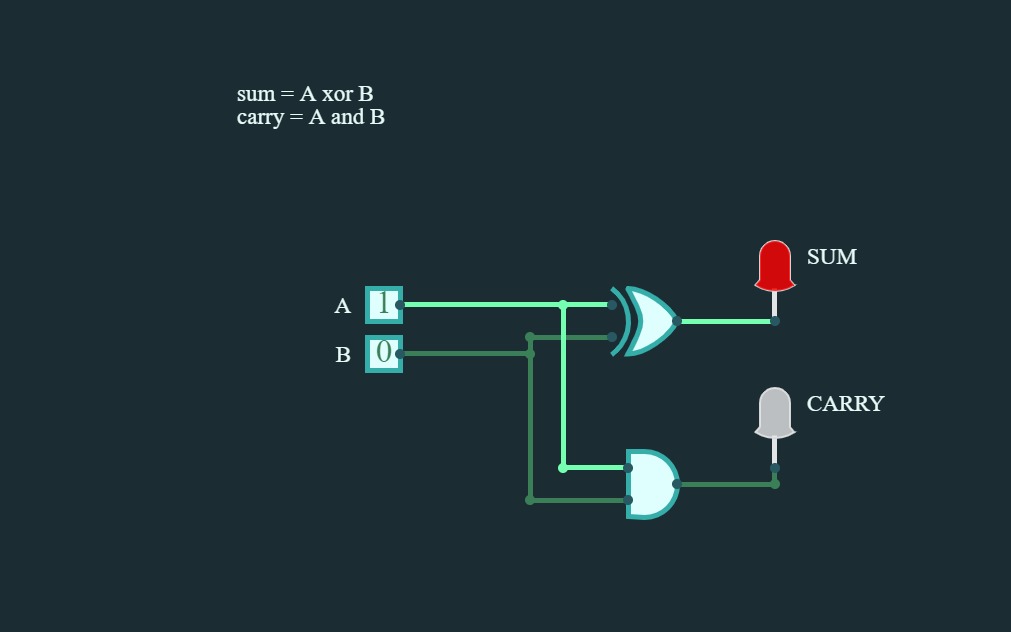
half_adder
half_adder
Digital gtes
Digital gtes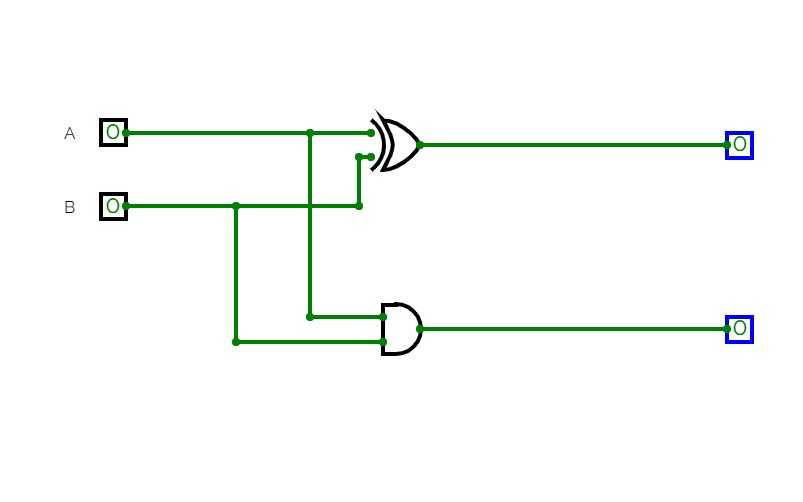
digital gates
digital gates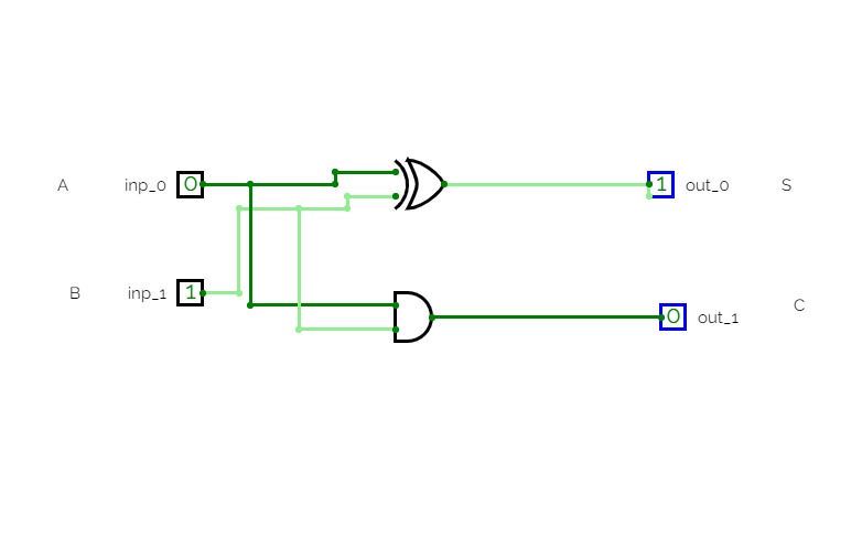
digital_gates
digital_gates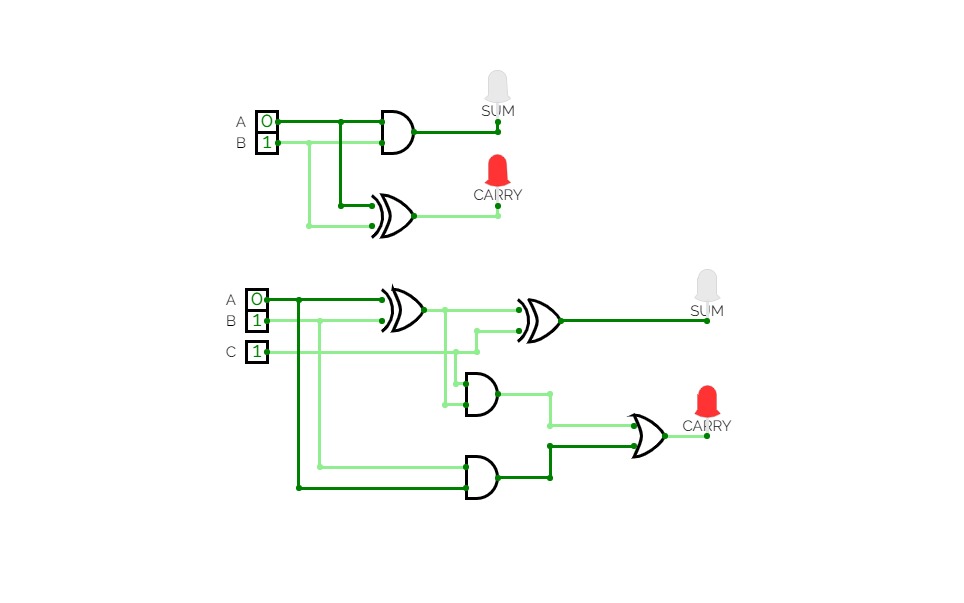
full adder
full adder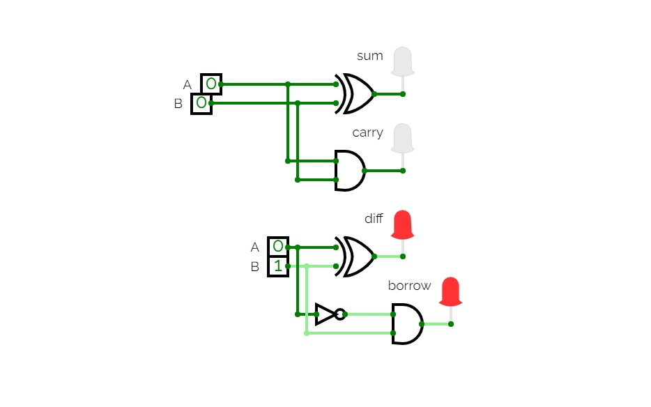
adder,subtractor
adder,subtractor
PRIYA
PRIYA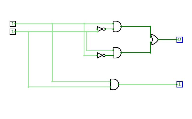
half adder
half adder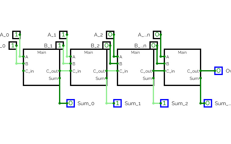
Lab 4
Lab 4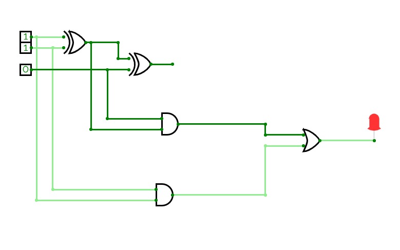
half adder
half adder
half adder
half adder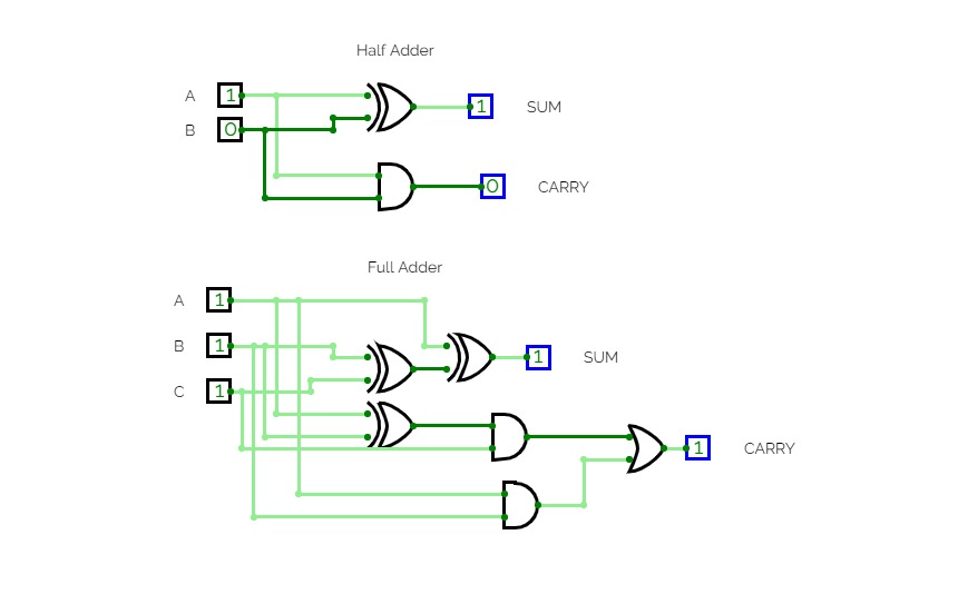
LAB2
LAB2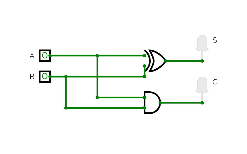
HALF ADDER
HALF ADDER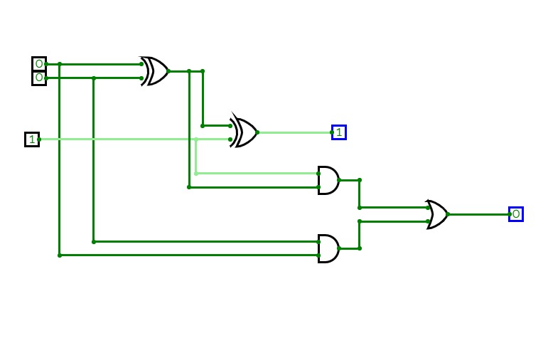
full adder
full adder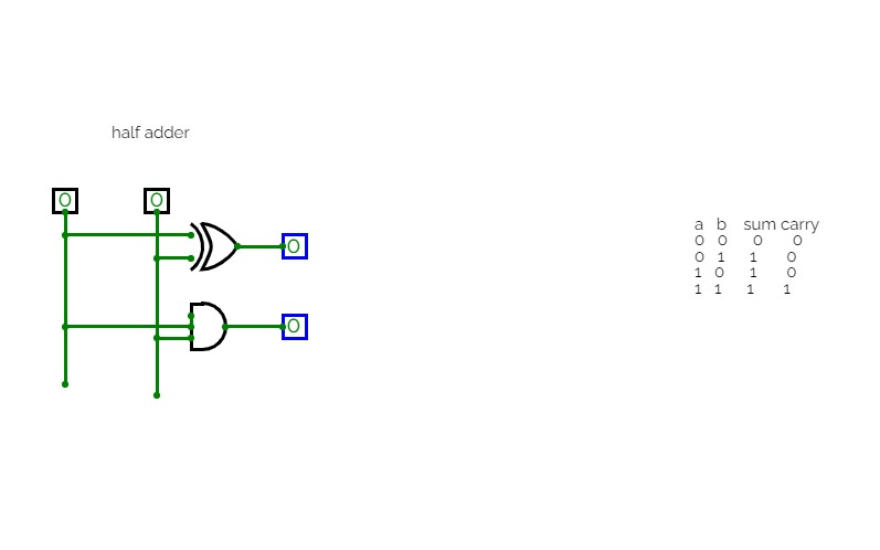
digital ele hilf adder
digital ele hilf adder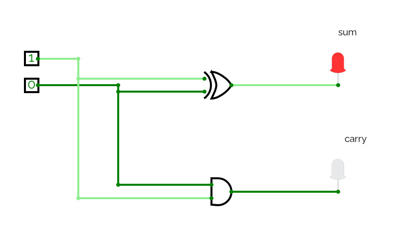
HalfAdder
HalfAdderadding 2 numbers
half adder and full adder
half adder and full adder.
Rohit project
Rohit project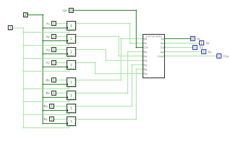
Bipin kushwaha
Bipin kushwaha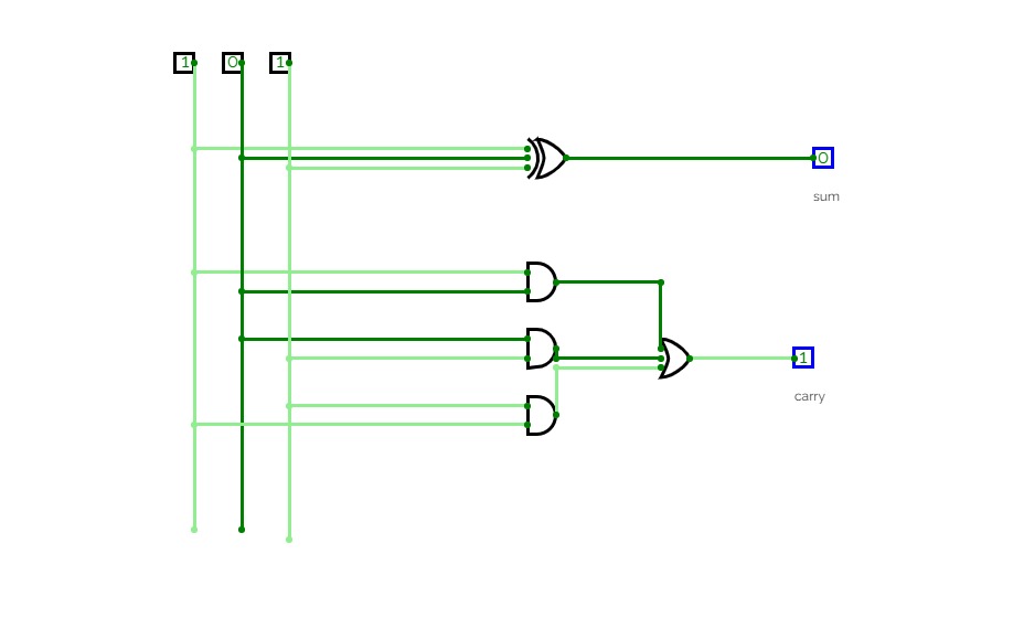
half adder and full adder
half adder and full adder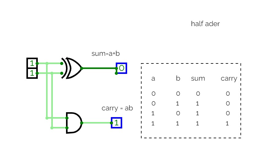
lab1exp6
lab1exp6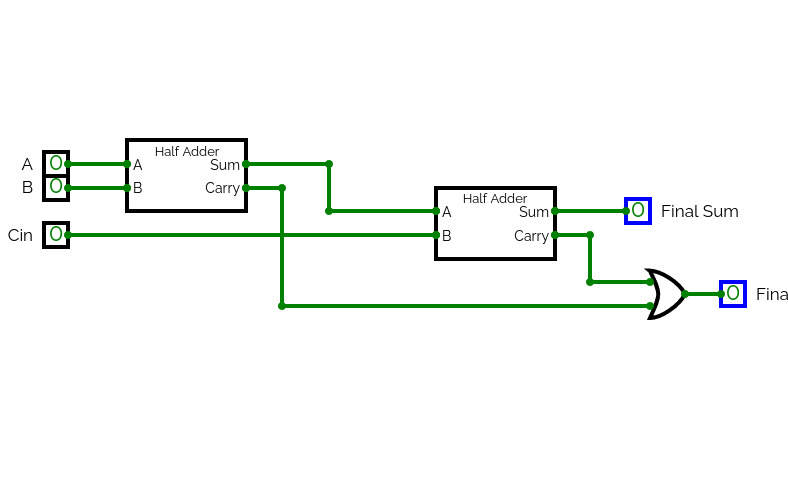
21bds0194
21bds0194
bittaraj roy
bittaraj roy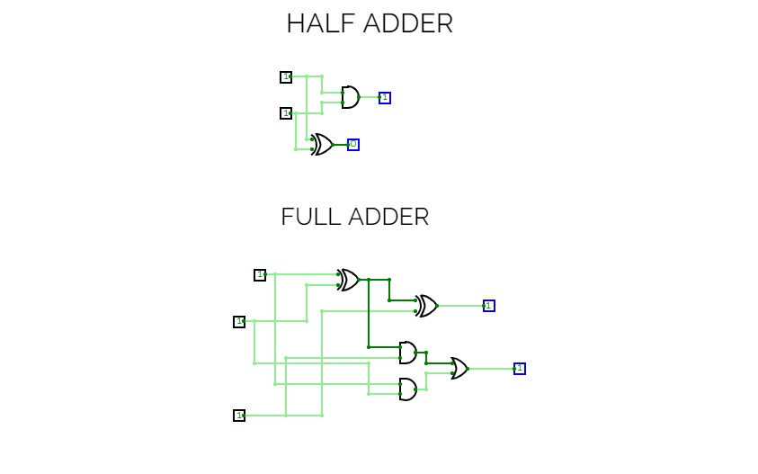
PROJECT 2
PROJECT 2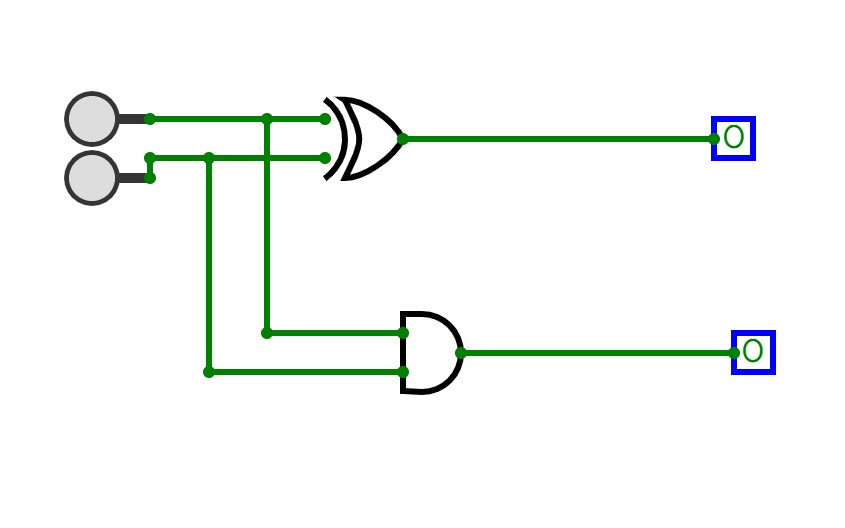
harsh
harsh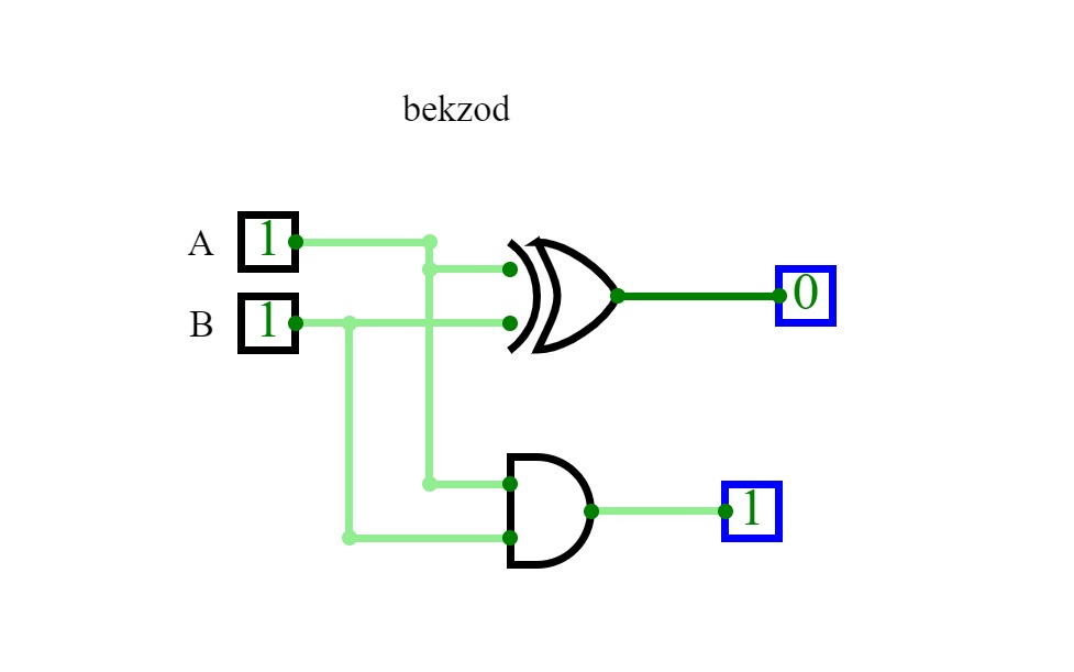
Half adder Full adder Paralell
Half adder Full adder Paralell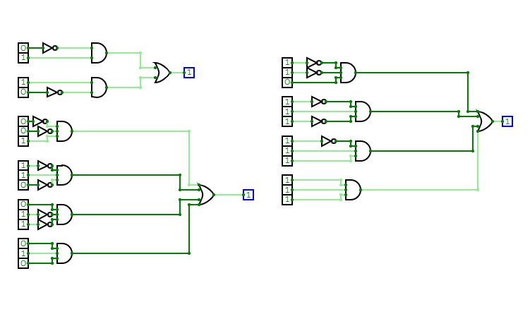
half adder
half adder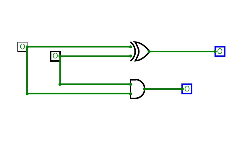
half adder t1
half adder t1half adder with 0,0 input
Half adder
Half adder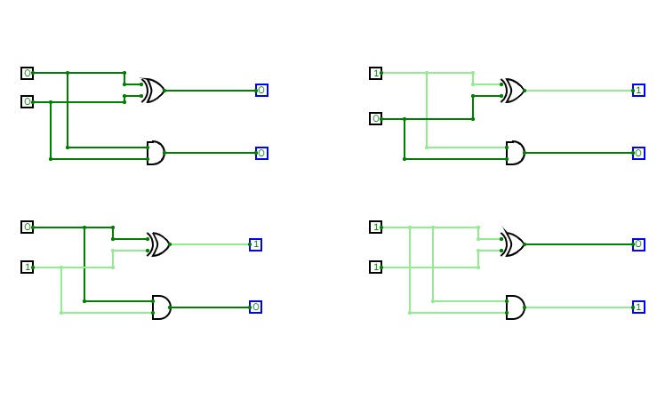
half adder(project 2)
half adder(project 2)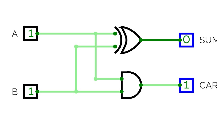
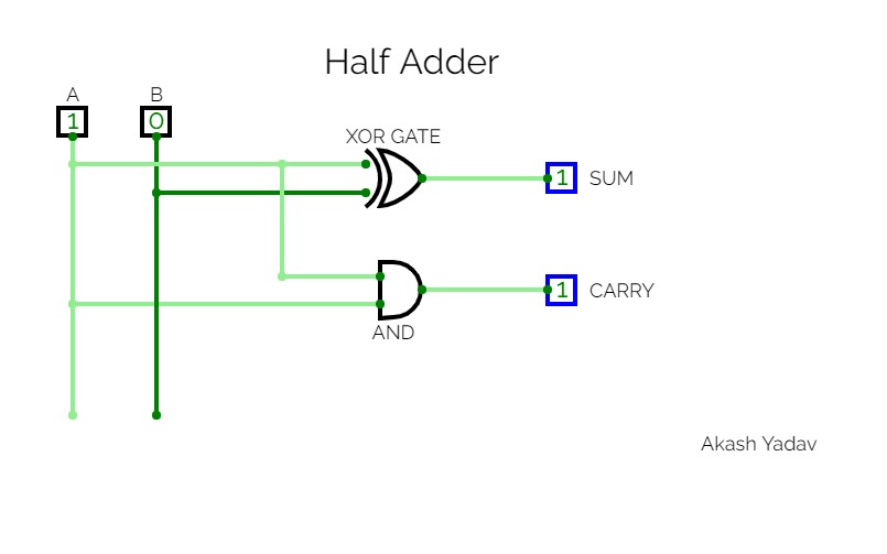
Half Adder
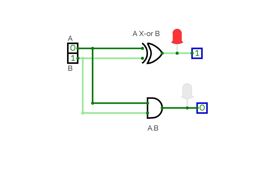
Half AdderHalf adder is a combinational logic circuit with two inputs and two outputs. The half adder circuit is designed to add two single bit binary number A and B. It is the basic building block for the addition of two single-bit numbers. This circuit has two outputs carry and sum.
ece project
ece project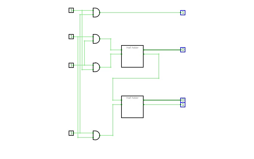

2*2 Binary Multiplier
2*2 Binary MultiplierFunction of 2*2 binary multiplier
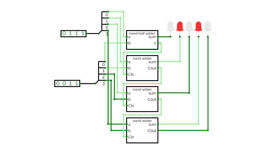
nand adder
nand adder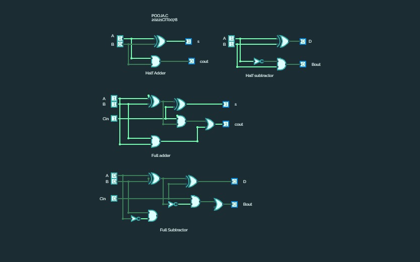
project 2
project 2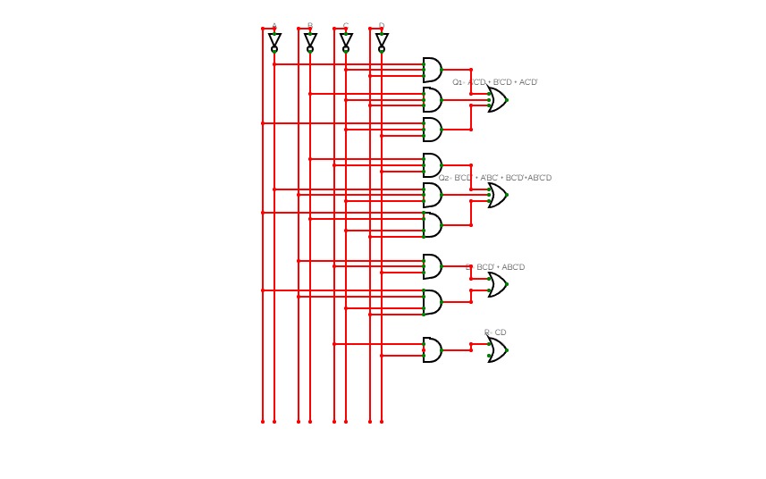
D FLIP FLOP CIRCUIT
D FLIP FLOP CIRCUIT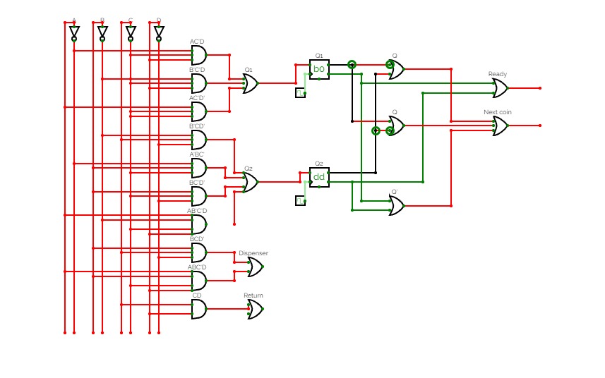
D FLIP FLOP CIRCUIT
D FLIP FLOP CIRCUIT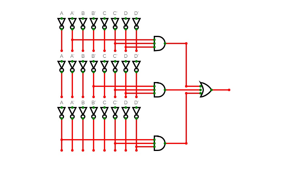
logic expressions
logic expressions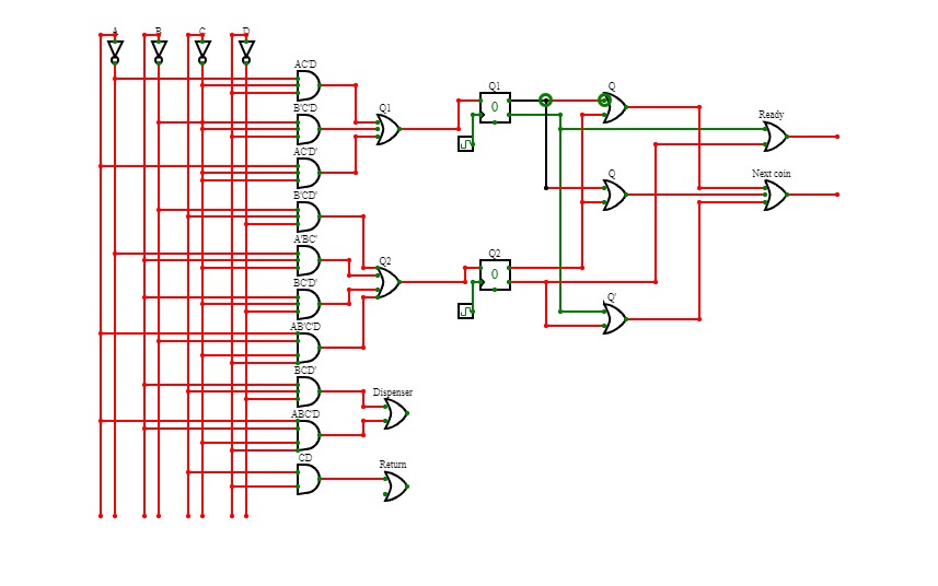
D FLIP FLOP CIRCUIT
D FLIP FLOP CIRCUIT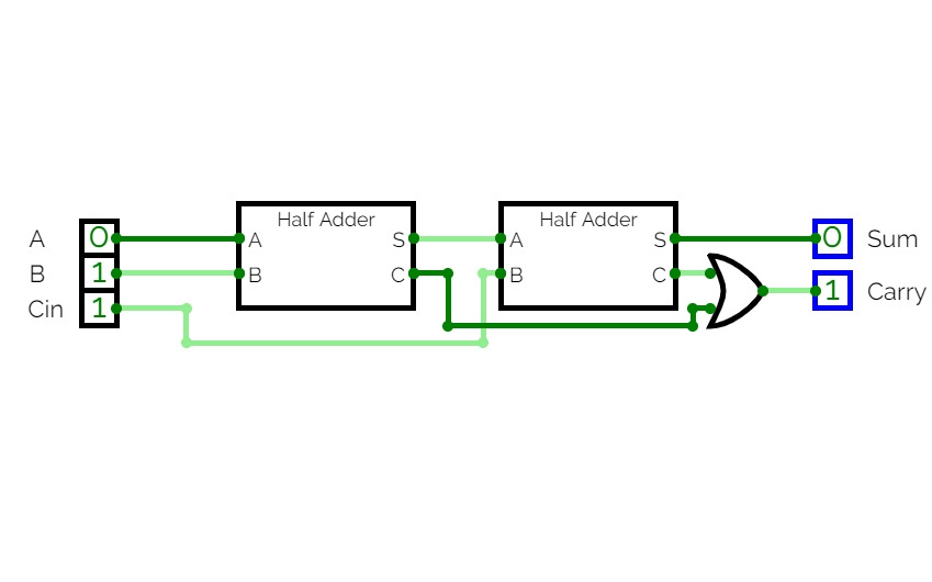
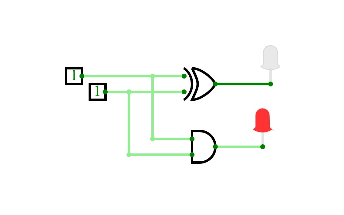
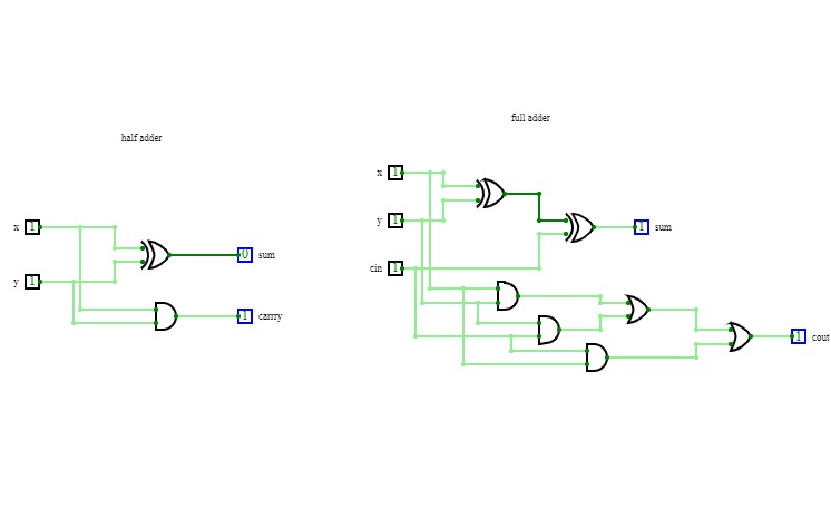
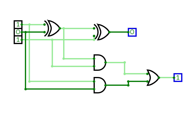
Full adder using half adder
Full adder using half adderThis is full adder using half adder. Here even truth table is given for your conveniency.
Adders
Adders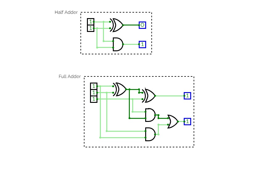
Program 2 - Half and Full adder
Program 2 - Half and Full adderHalf adder and full adder circuit
half adder
half adderhalf adder
MULTIPLIXER
MULTIPLIXER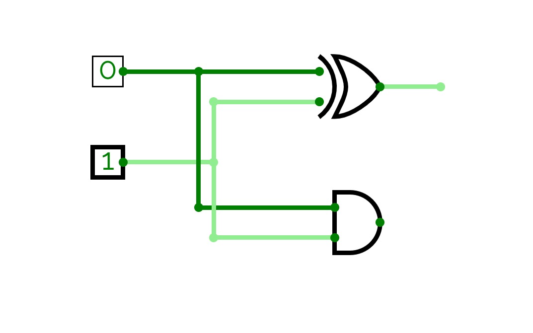
Half Adder DLD Assignment
Half Adder DLD Assignmentgroup members :
M. Usman Tayyab
First 5 questions
Tehreem Zafar
Second 5 assignments questions
M. Waleed
third 5 assignments questions
Aqib Yaseen
Fourth 5 assignments questions
Zeeshan Abid
Fifth 5 assignments questions
Ahmad Raza
Sixth 5 assignments questions

HALF ADDER
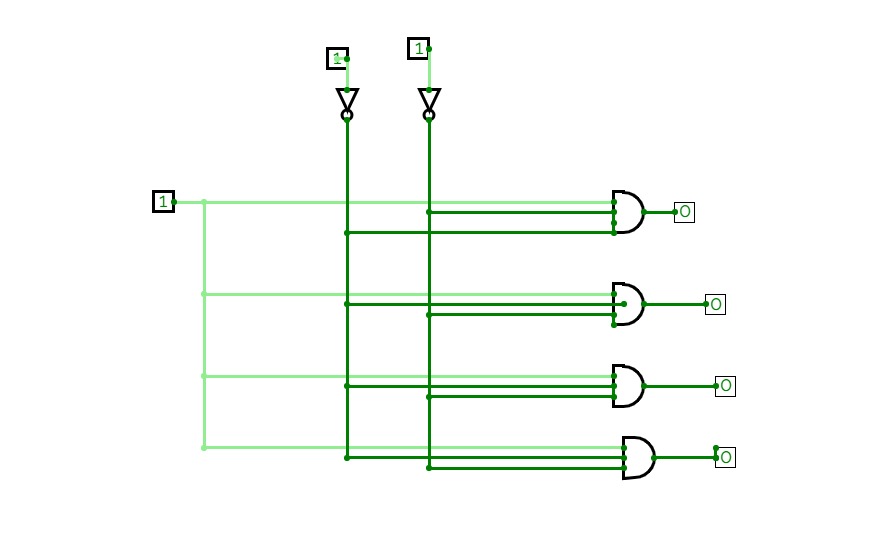
HALF ADDERCircuit of Half Adder with a circuit diagram of decoder

Qasim
Qasim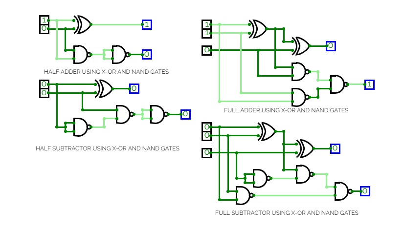
experiment 2 level2
experiment 2 level2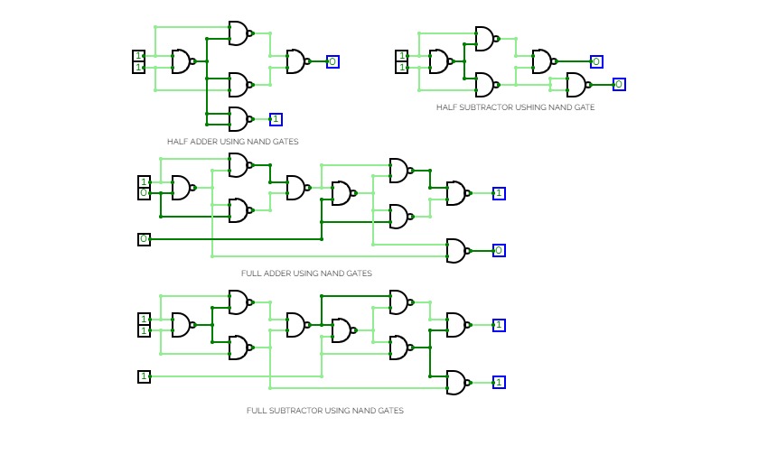
experiment 2 level3
experiment 2 level3
S.jwalitha
S.jwalitha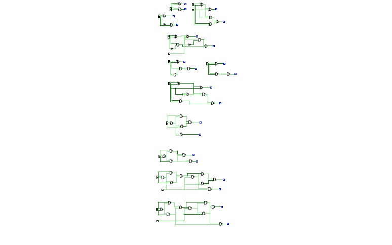
Varshini
Varshini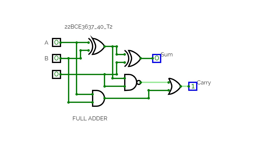
T2_22BCE3637_40
T2_22BCE3637_40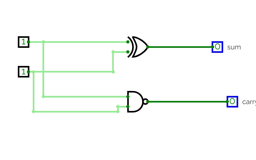
0675
0675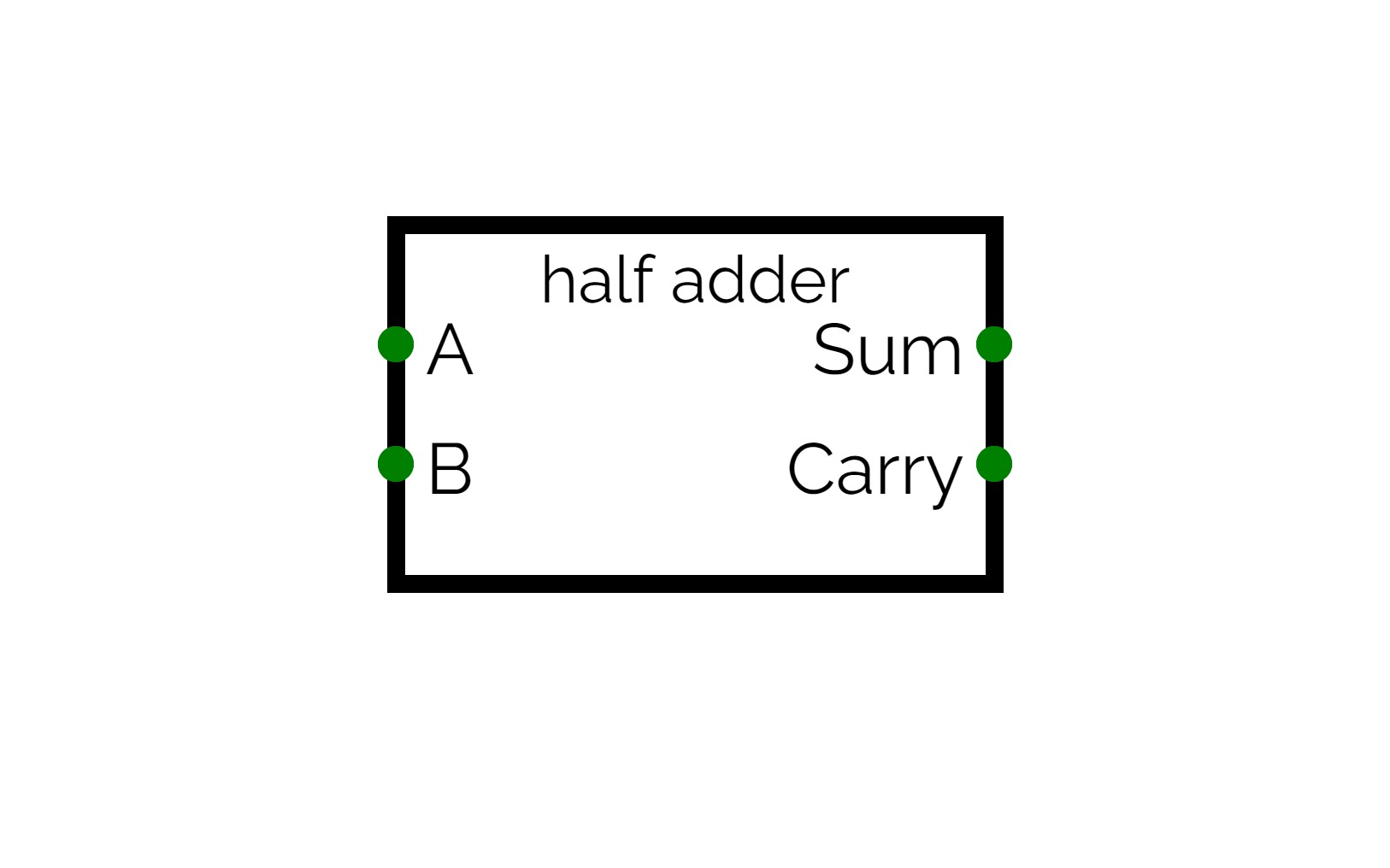
half adder
half adder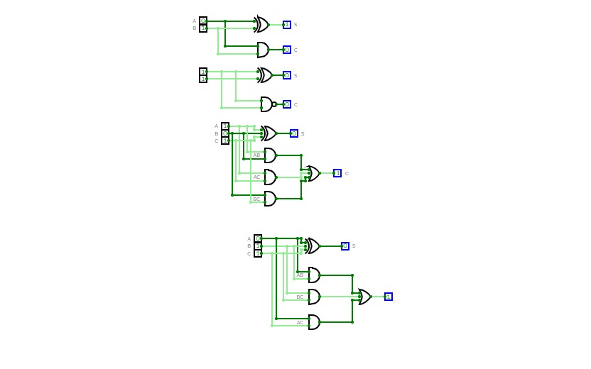
exp-2_2200290110060.pdf
exp-2_2200290110060.pdf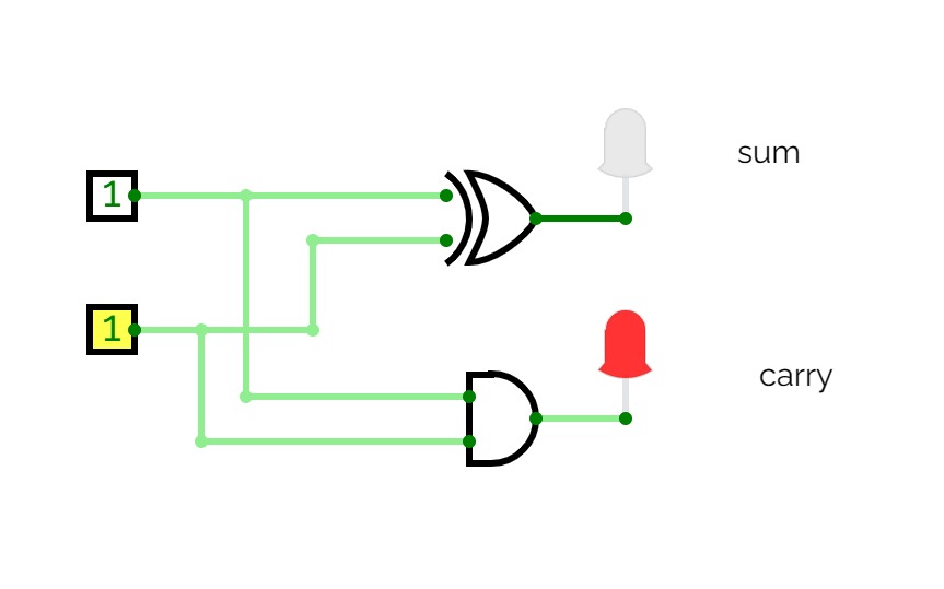
Untitled
Untitled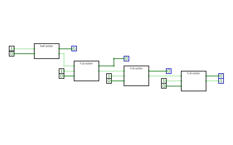
Untitled
Untitled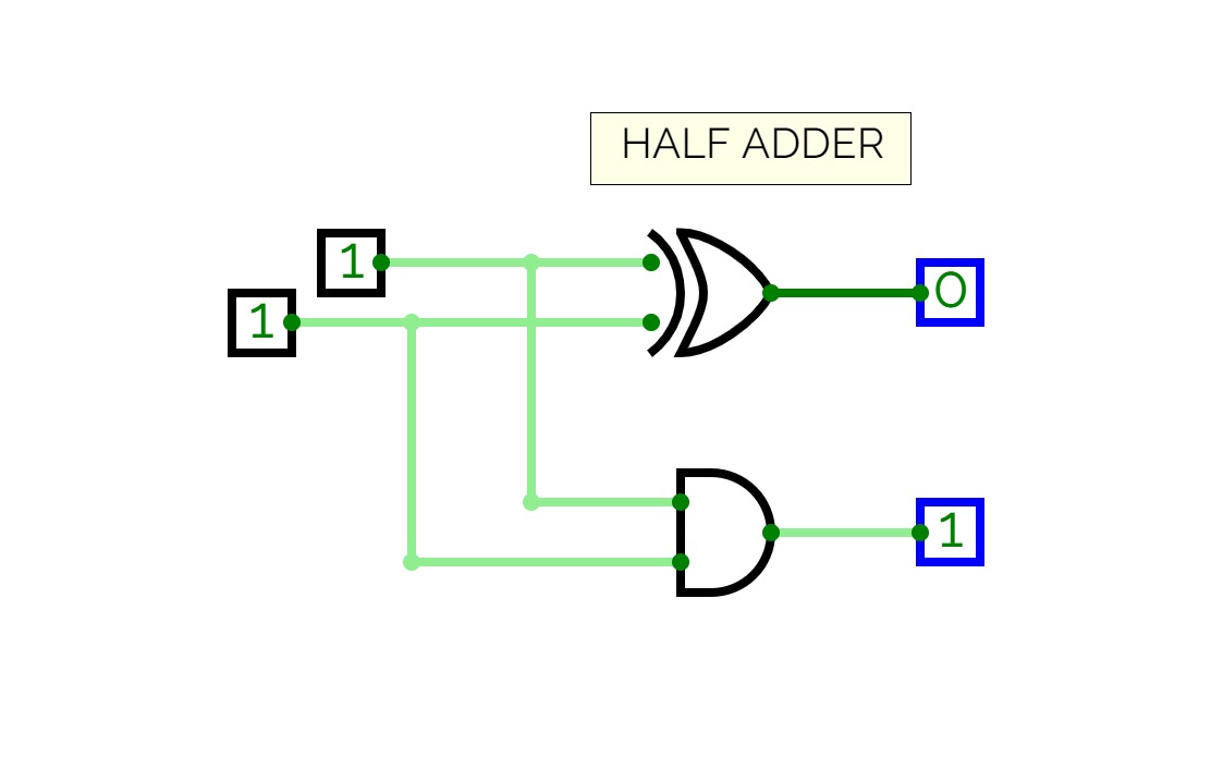
half adder
half adderhalf adder
team baka
team baka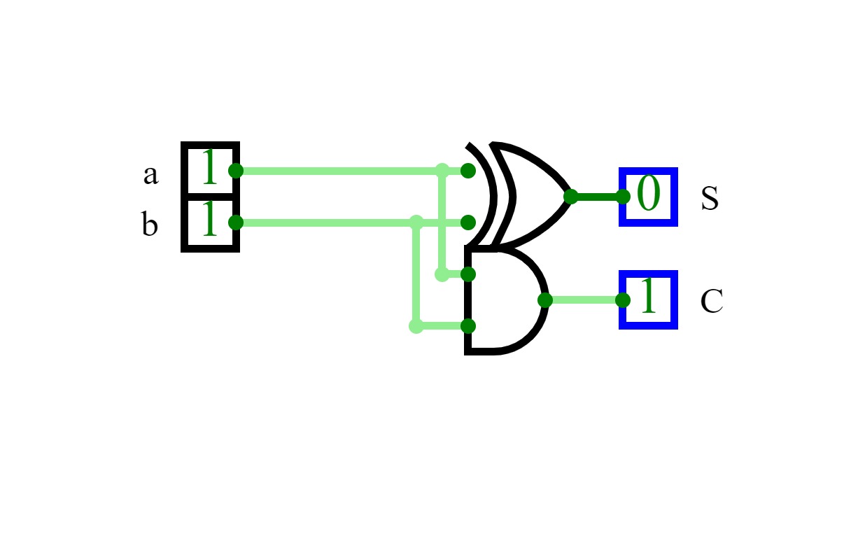
24060132140184,Minggu ke 3
24060132140184,Minggu ke 3Membuat rangkaian dari half adder, full adder, dan 2x half adder
Untitled
Untitled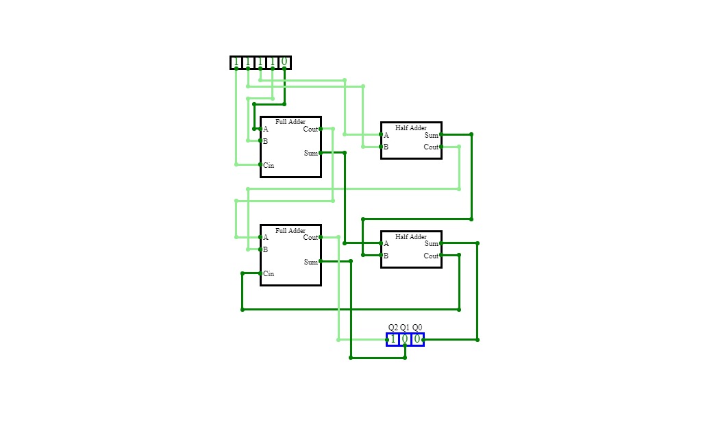
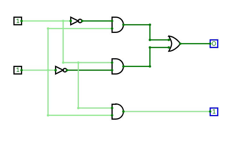
Count 1s
Count 1sBased of full adder and half adder circuit, build a circuit that count 1s of input.
harsh
harsh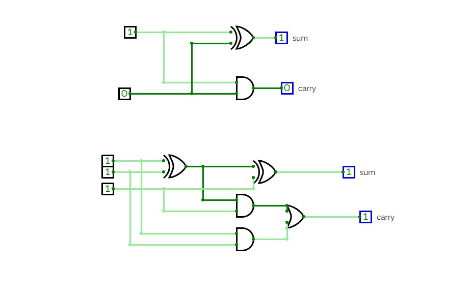
half and full adder
half and full adder
Rahul kumar
Rahul kumar
Untitled
Untitled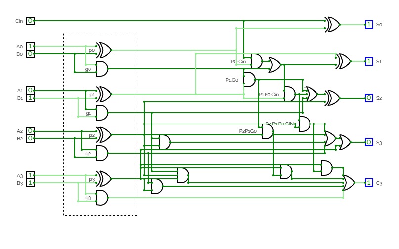
SubCircuits
SubCircuits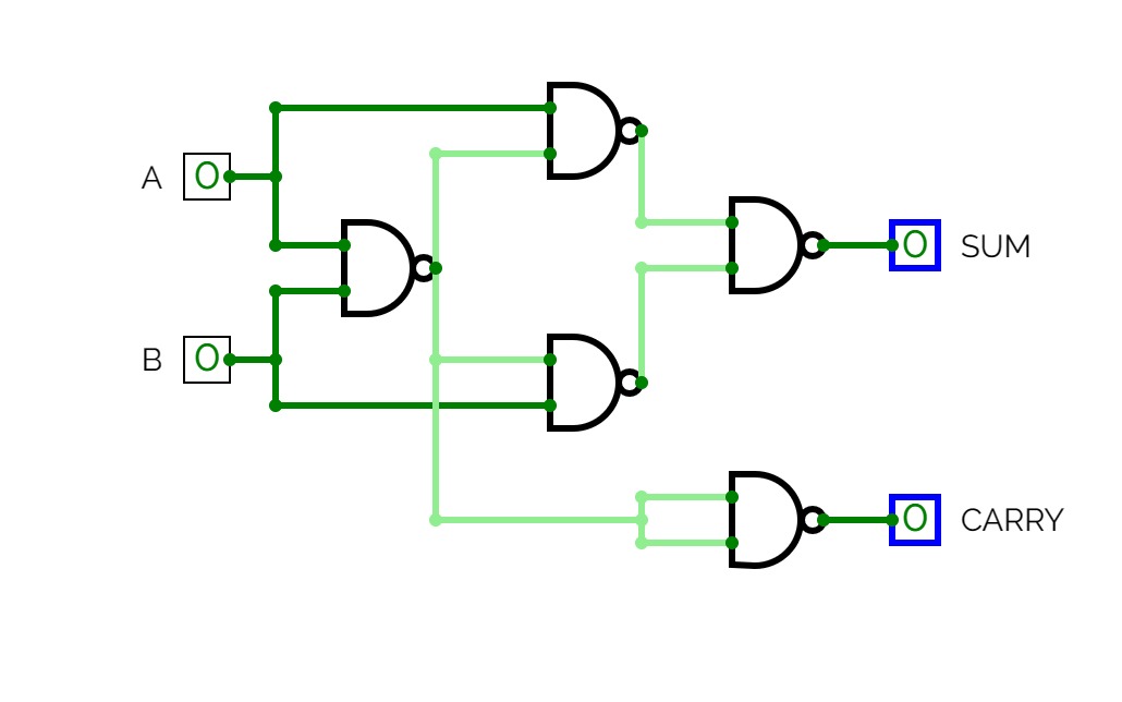
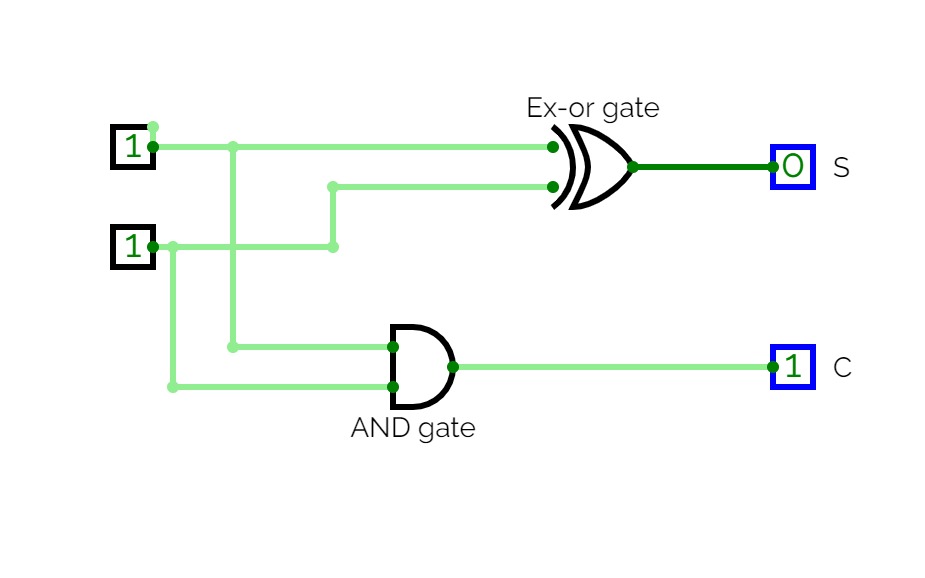
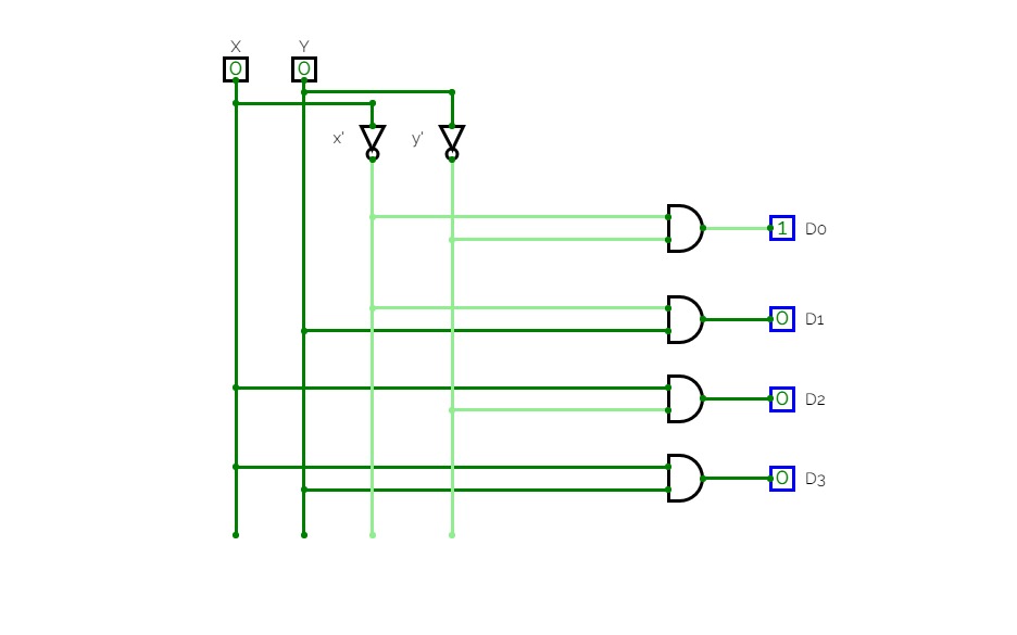
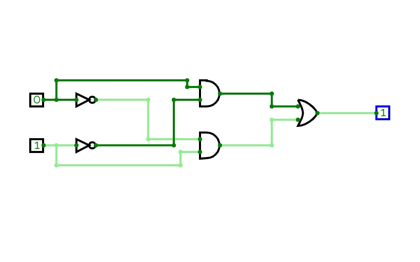
Half adder using NAND gate
Half adder using NAND gate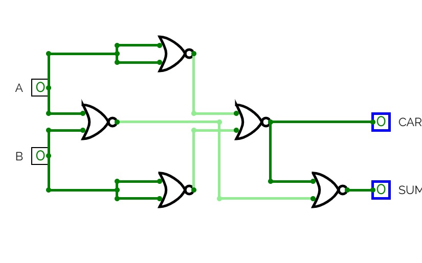
Half adder using NOR gate
Half adder using NOR gate
lab2 que2
lab2 que2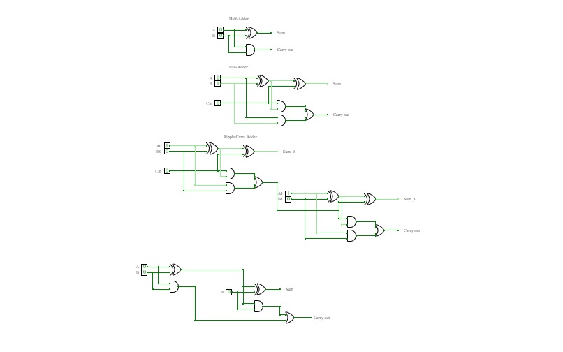
Half and Full Adders
Half and Full Adders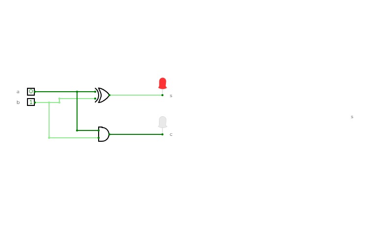

experiment-4
experiment-4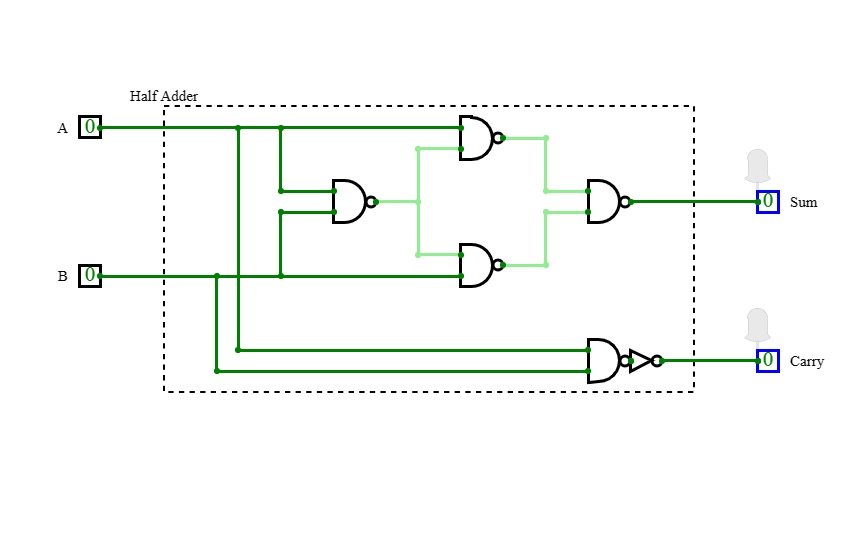
Adders
Adders
exp 4
exp 4trinadh done by project

Adder
Adder
half adder
half adder
ADDER CIRCUIT
ADDER CIRCUIT
half adder
half adderthis is the half adder circuit


