

8 to 1 MuX
8 to 1 MuXMultiplexer
MultiplexerMultiplexers
Multiplexer
MultiplexerMultiplexer

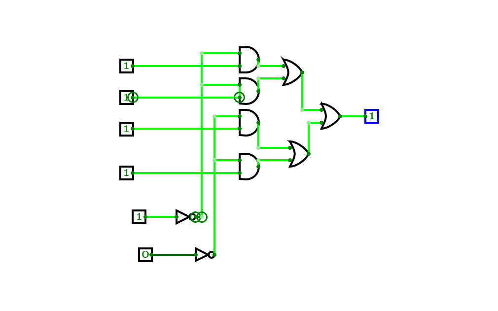
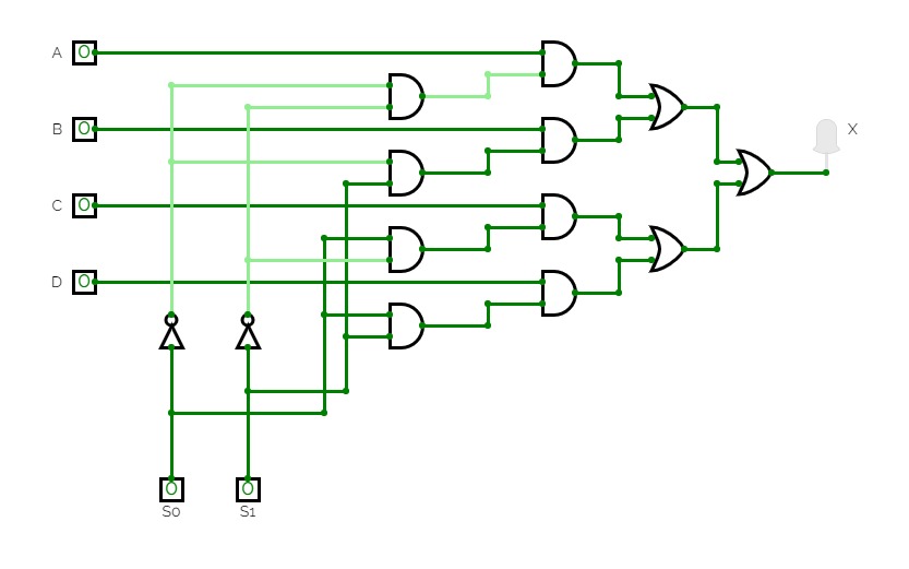
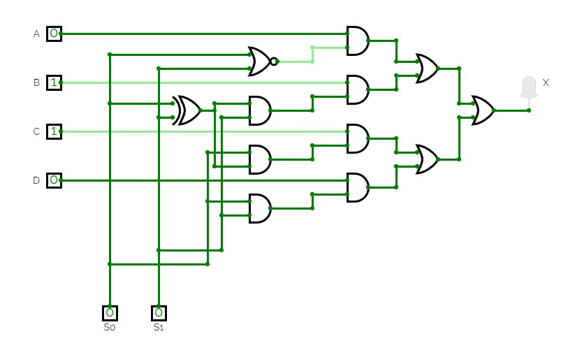
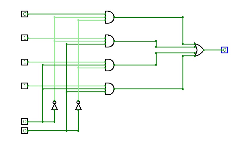
Boolean expression realization using single 4:1 MUX using LSB reduction
Boolean expression realization using single 4:1 MUX using LSB reduction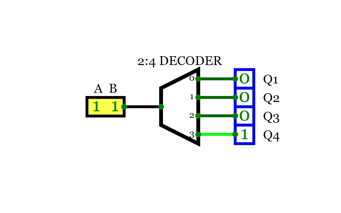
2:4 Decoder ( Binary Decoder)
2:4 Decoder ( Binary Decoder)For a decoder, If the input is a N bit binary number, then the output will be one the lines of the 2^N output lines.
So, for a 2-bit binary input, there will be 2^2 output lines and only one of the output lines will be active according to the binary combination of the inputs. This type of decoder is known as 2 to 4 decoder.
A
B
Q0
Q1
Q2
Q4
0
0
1
0
0
0
0
1
0
1
0
0
1
0
0
0
1
1
1
0
0
0
1
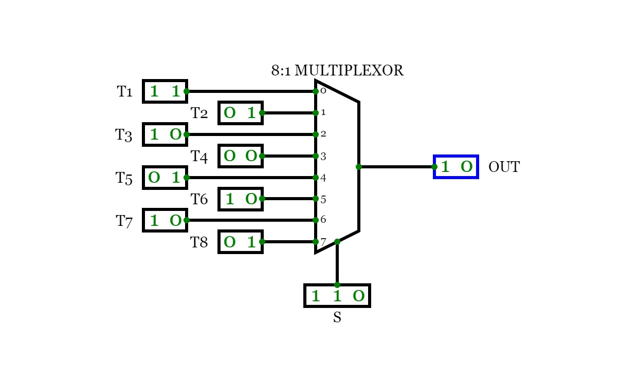
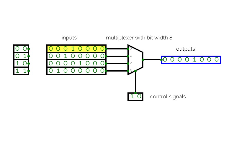
8:1 Multiplexer
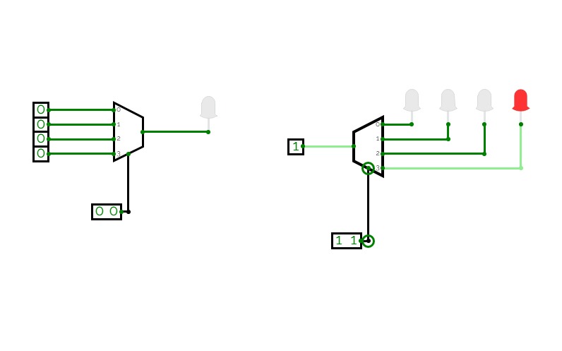
8:1 MultiplexerConsider a 8:1 multiplexer that takes 8 two-bit inputs (T8 to T1), three-bit control signal (S) and has an output (Out). This Type of multiplexer is known as a 8 to 1 multiplexer. The truth table is given below:
S2
S1
S0
OUT
0
0
0
T1
0
0
1
T2
0
1
0
T3
0
1
1
T4
1
0
0
T5
1
0
1
T6
1
1
0
T7
1
1
1
T8
ALU
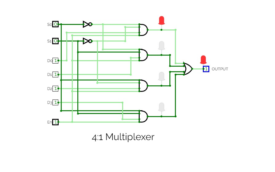
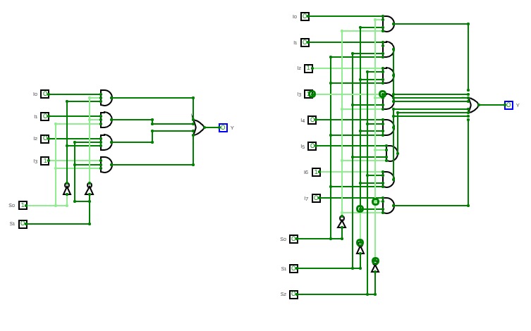
ALUThis is a circuit design for 4:1 Multiplexer
Simple 4x1 MUX
Simple 4x1 MUXCoursework for CPE111 course.
Fork the project to test the circuit.
Alternative 4x1 MUX
Alternative 4x1 MUXCoursework for CPE111.
Fork the project to test the circuit.
Multiplexer
Multiplexer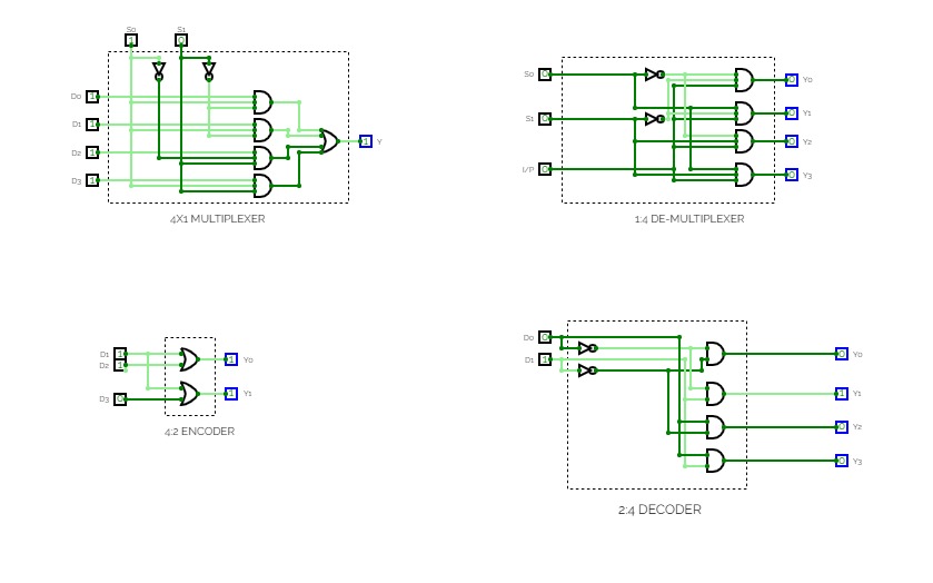
Experiment 2
Experiment 2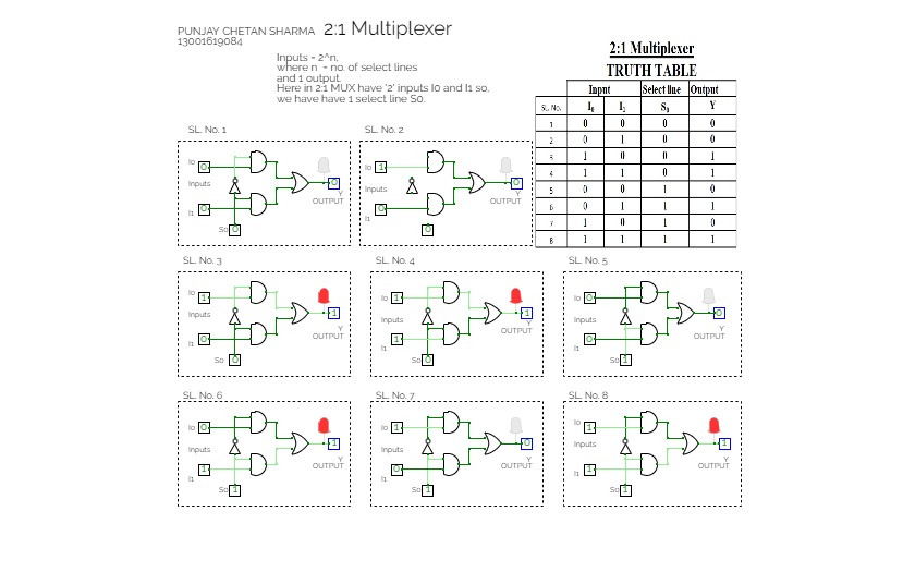
Multiplexer
Multiplexer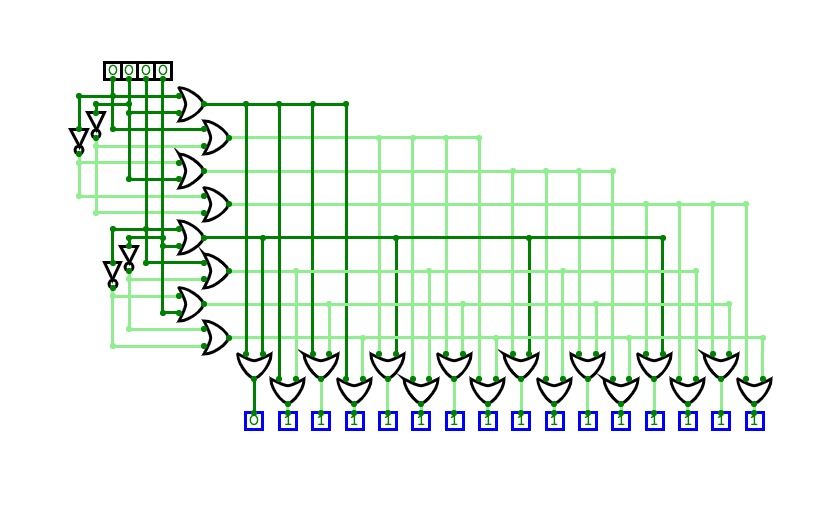

Multiplexer
MultiplexerMultiplexer made from NOT and 2-Input OR gates
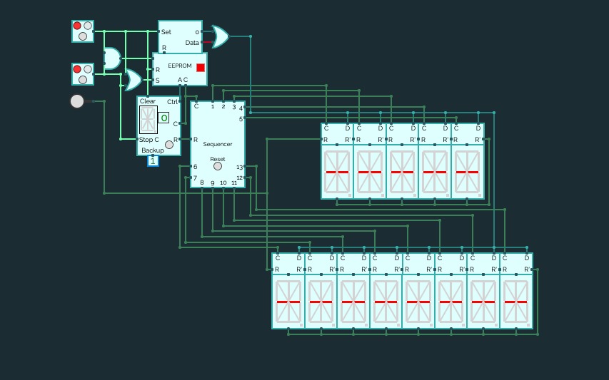

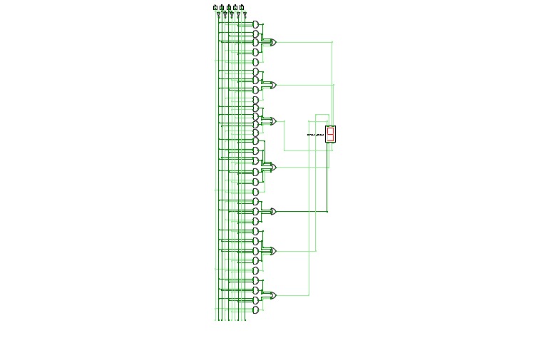
Asynchronous 16 - Segment Array
Asynchronous 16 - Segment ArrayInstructions
Set both buttons to off (RED). Now reset the sequencer and turn on button 1 and 2 (set to GREEN).
Button 1 controls the data fed to the displays.
OFF = Clear all displays ON = Programmed message
Button 2 controls the clock.
To change the message, dump the core or reset the EEPROM and rewrite the suitable data for the 16-Segment Displays. If the new message contains lesser or more letters/numbers to show, make suitable changes to the Sequencer and change the number of displays used.
4:1 Multiplexer by Souvik Ghosh
4:1 Multiplexer by Souvik Ghosh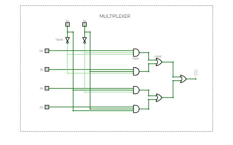
Experiment 7
Experiment 7Abdul Muthalib
Roll no: 2
Reg no: 20919002
4 x 1 MUX
4 x 1 MUX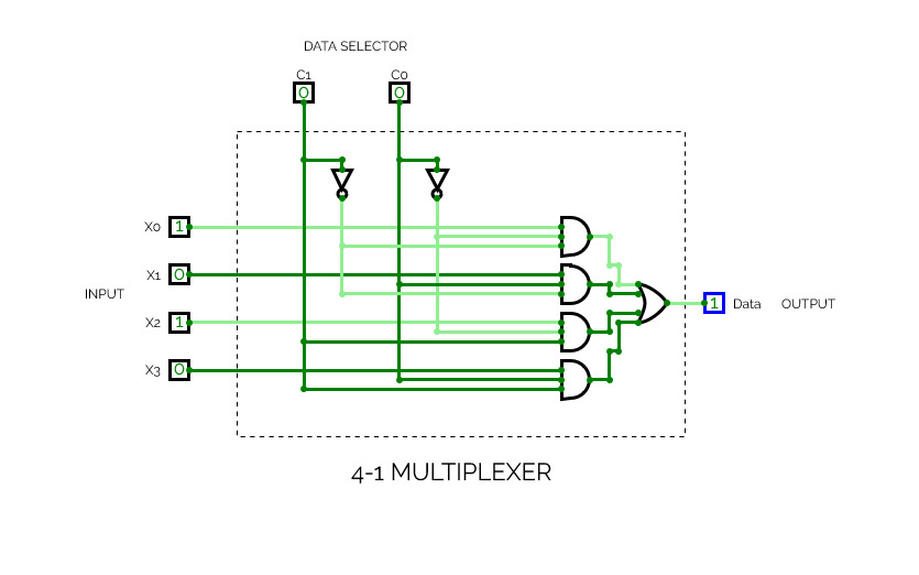

4-1 Multiplexer
4-1 Multiplexer4-1 Multiplexer
4-input
2-data selector
1-data channel (output)
MUX DEMUX
MUX DEMUX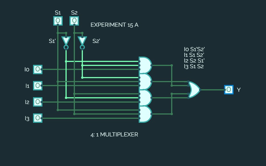

EXPERIMENT 15A
EXPERIMENT 15AImplementation of a MUX using Basic Gates
Untitled
UntitledClassification of Combinational circuit
2 Channel Multiplexer
2 Channel Multiplexer
4 Channel Multiplexer
4 Channel Multiplexer
8 Channel Multiplexer
8 Channel Multiplexer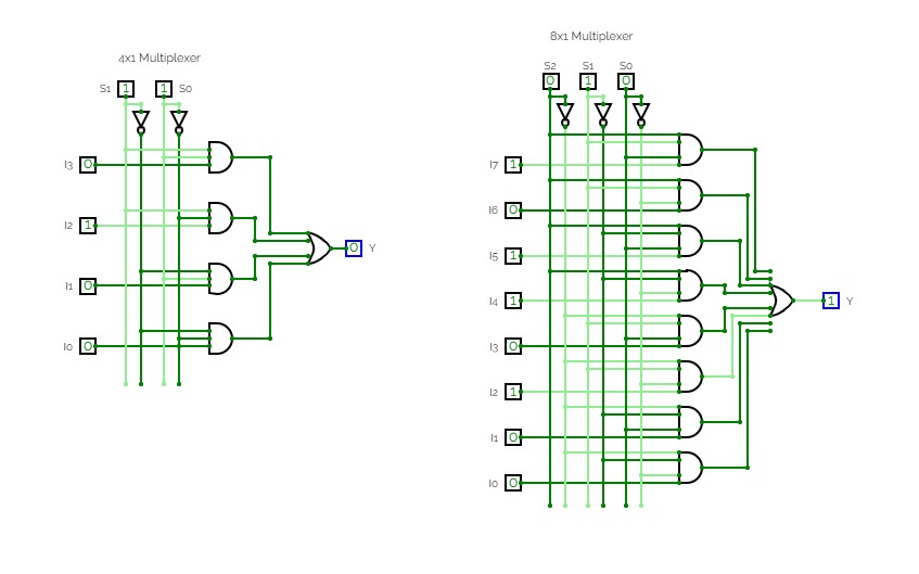
Implement 4x1 and 8x1 multiplexer.
Implement 4x1 and 8x1 multiplexer.Multiplexer - It is a combinational digital circuit that forward data from one of the 2n input lines to a single output line on the base of n selection lines.

Multiplexer 4*1
Multiplexer 4*1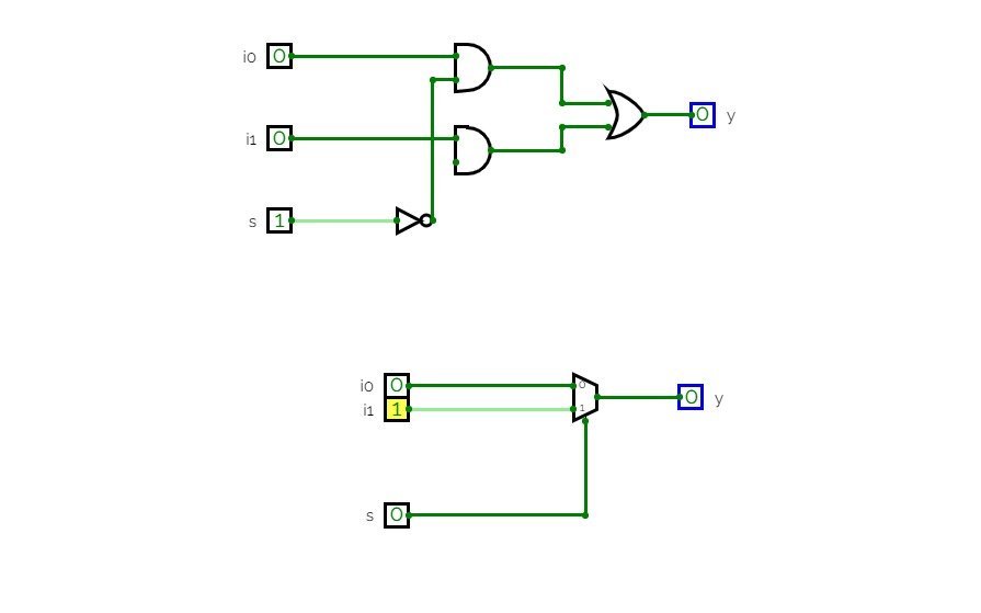

experiment 03(d)
experiment 03(d)D.L.F experiment 03(d)
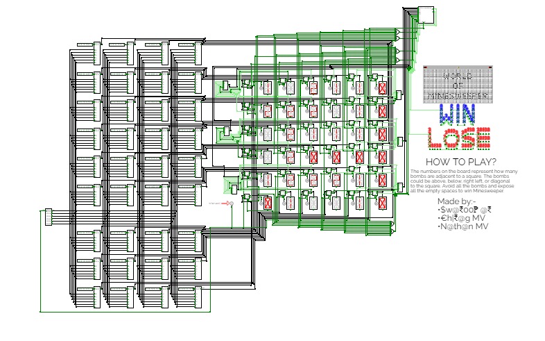
MineSweeper
MineSweeperMinesweeper: The game
Multiplexer example
Multiplexer example
3 Bit Multiplexer
3 Bit Multiplexer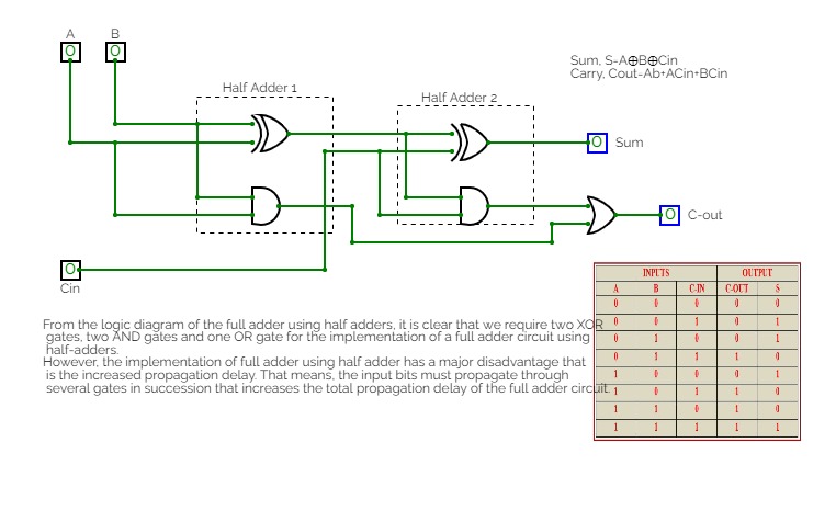

LAB PROJECT
LAB PROJECTClass lab project
Untitled
Untitled4:1 MUX

Dhairya Gupta
Dhairya Gupta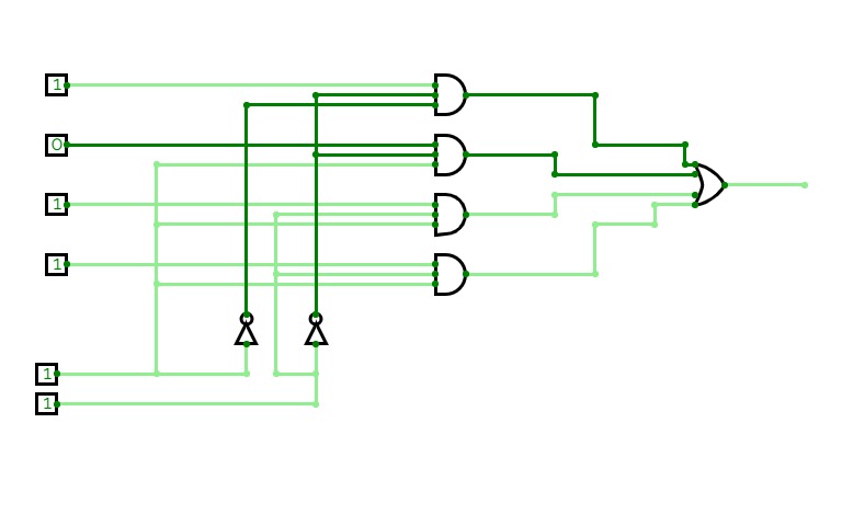
Coa
Coa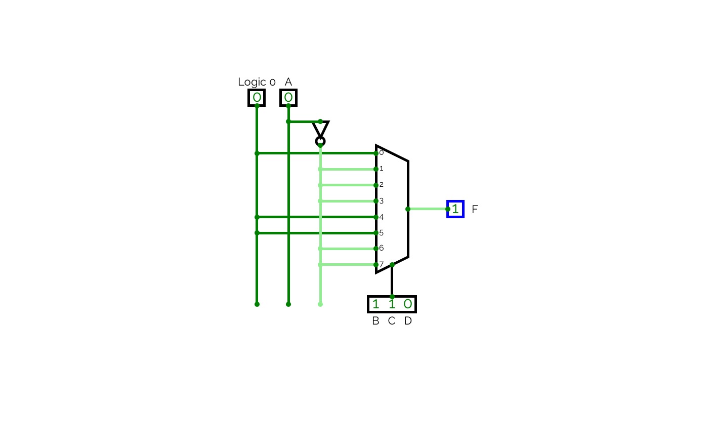

SBA_2 - Statement 2
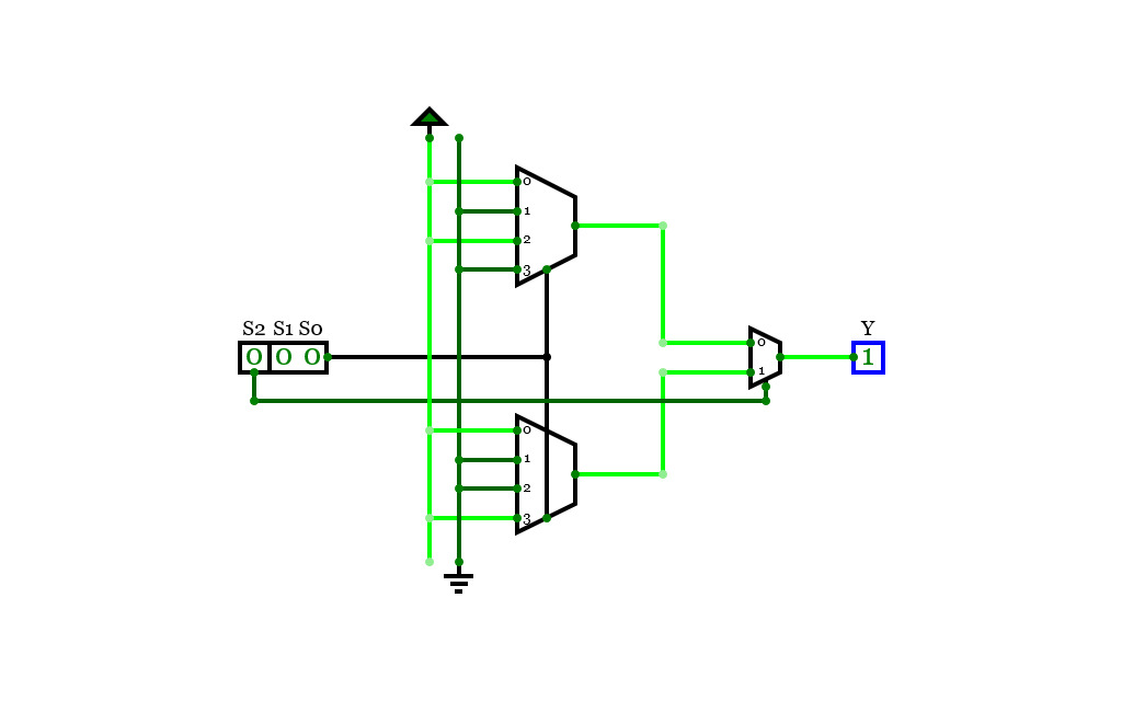
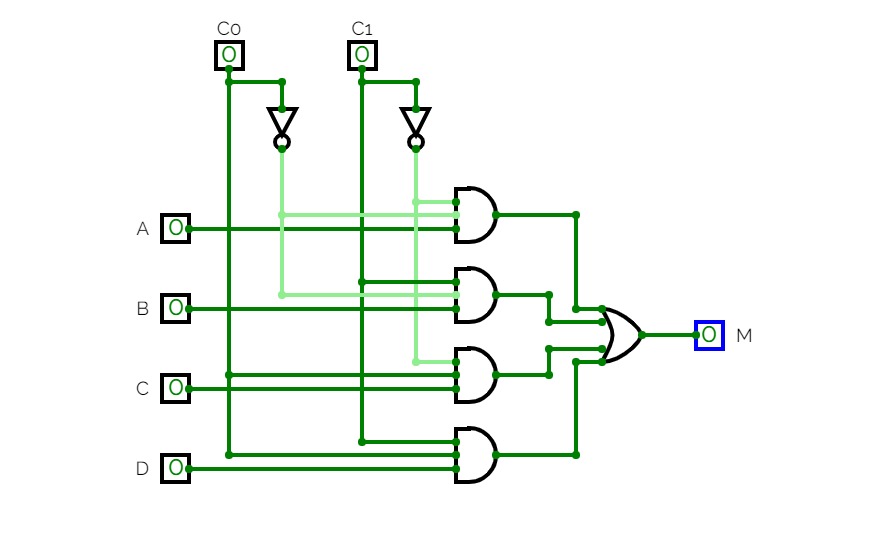
SBA_2 - Statement 2This circuit demonstrates a way to simplify the given boolean expression using multiplexers.
Multiplexer
Multiplexer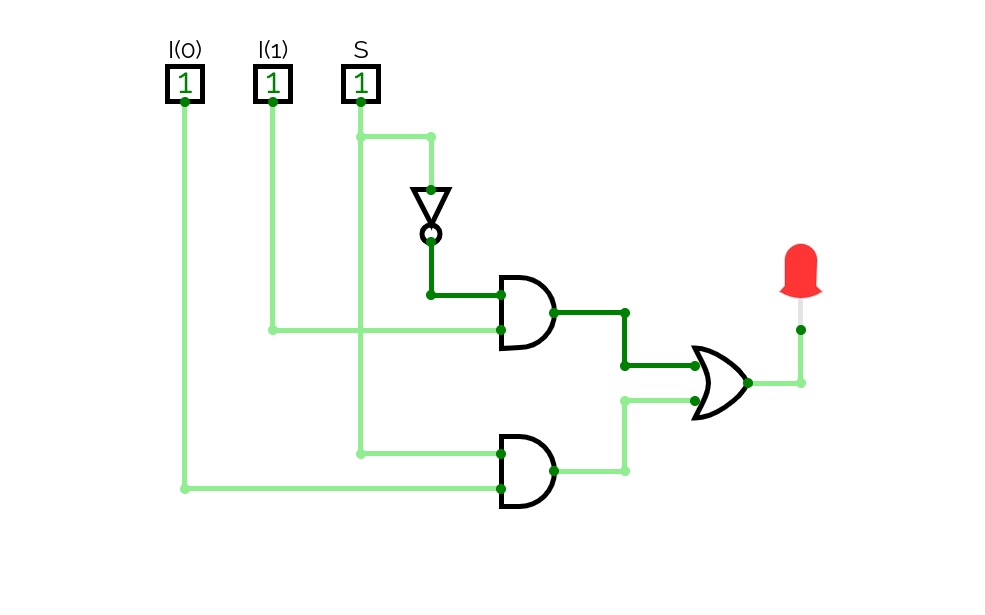
MUX 2:1
MUX 2:1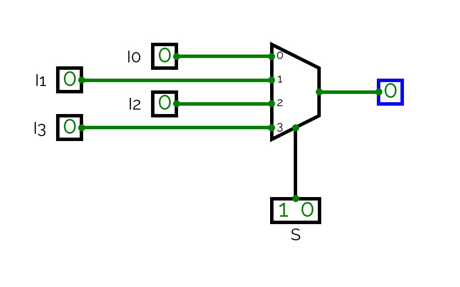
MUX 4:1
MUX 4:1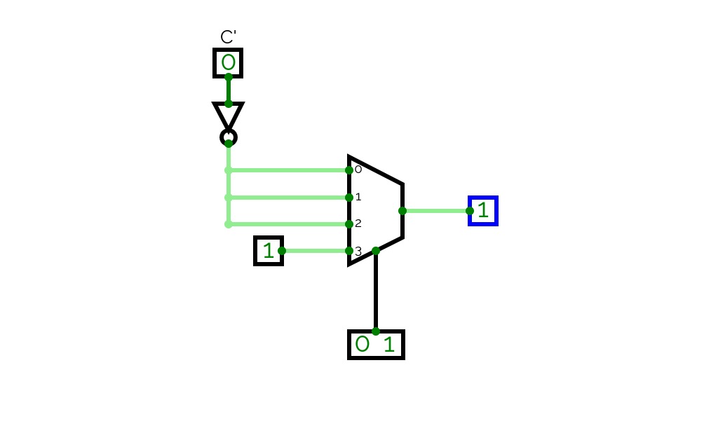
MUX 8:1 (0, 2, 4, 6,7)
MUX 8:1 (0, 2, 4, 6,7)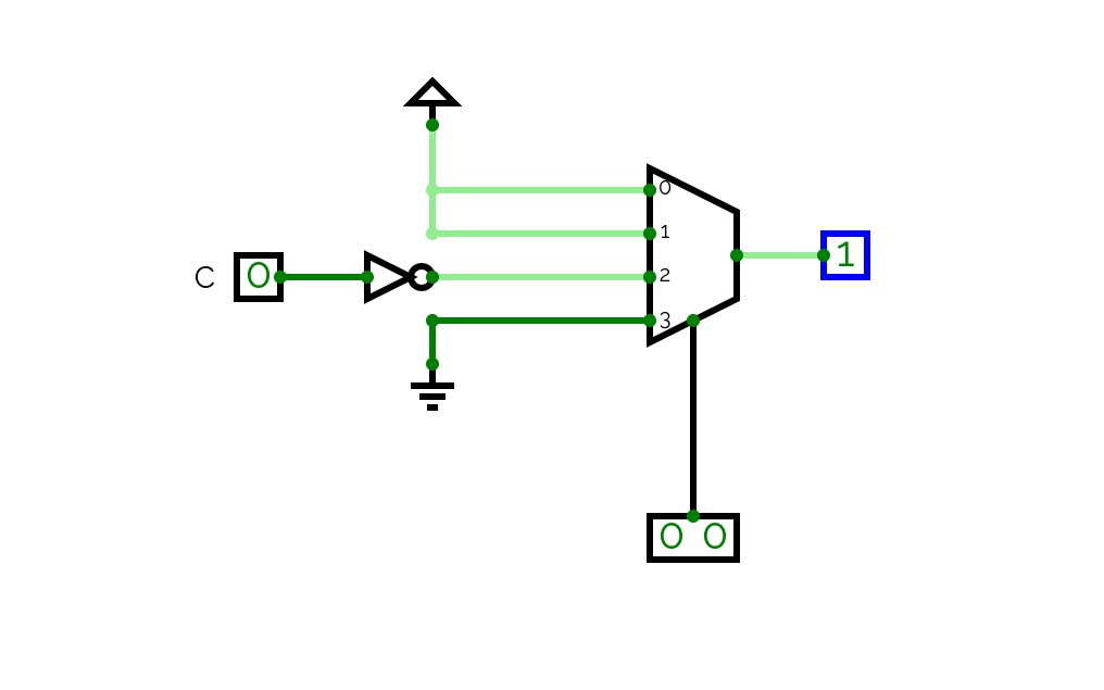
MUX (1,2,3,4)
MUX (1,2,3,4)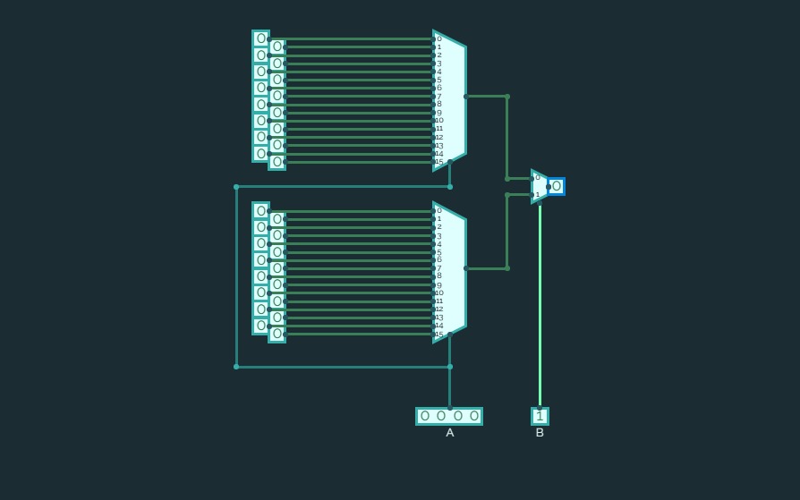
32 : 1 mux using 16 : 1 mux
32 : 1 mux using 16 : 1 mux
Mux/Demux
Mux/Demux

Computer Logic
Computer LogicA little experiment of mine where I have a crap ton of digital logic stuff. Below I'll just have the whole list
- Half & Full Adders
- Half & Full Subtractors
- 4 Bit Parallel Adders & Subtractors
- 1, 2, 4 & 8 bit comparators
- Encoders & Decoders
- Latches & Flip Flops
- Multiplexer
Implement function of your ID with Multiplexer.
Implement function of your ID with Multiplexer.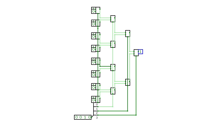

4-Bit Multiplexer
4-Bit MultiplexerMultiplexer lol
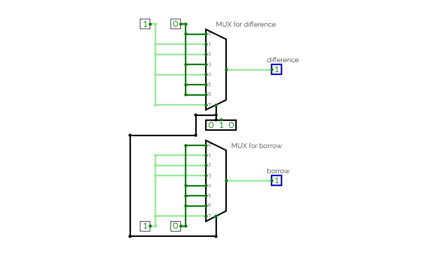
8 bit Subtractor circuit using MUX
8 bit Subtractor circuit using MUX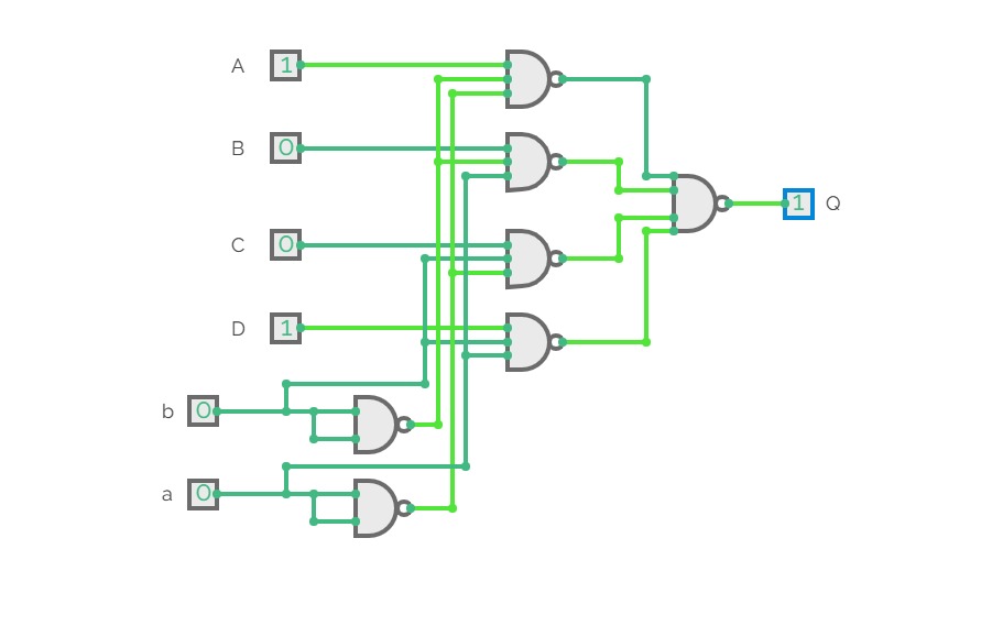
4-bit Multiplexer NAND Implementation
4-bit Multiplexer NAND Implementation4-bit Multiplexer implemented in NAND gates (both 3-input and 2-input)
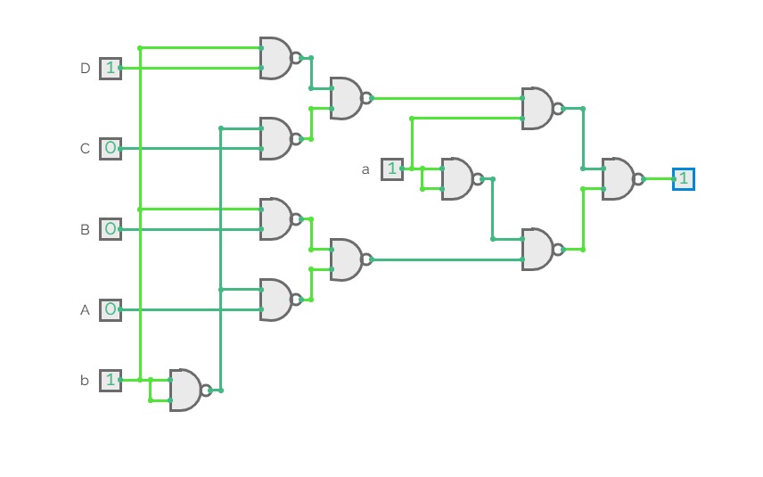
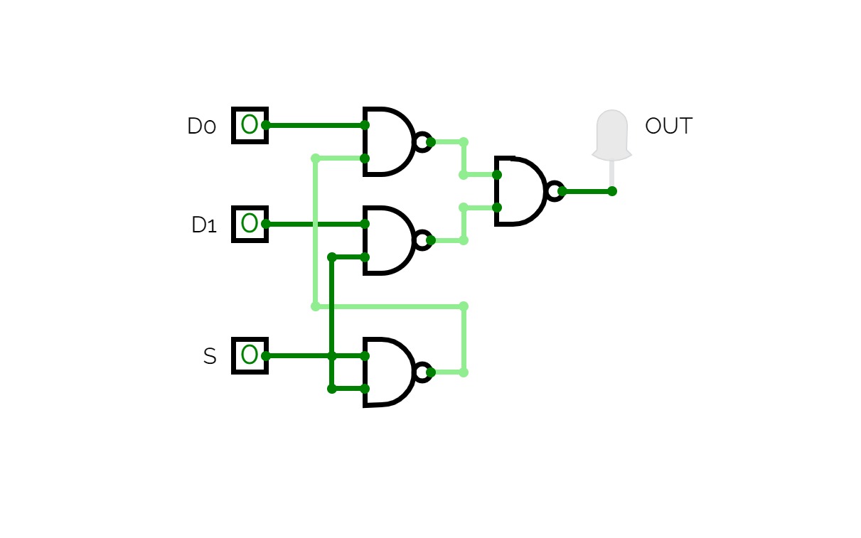
4-bit Multiplexer in 2-input NAND
4-bit Multiplexer in 2-input NAND4-bit Multiplexer implemented in 2-input NAND gates.

Expt 6
Expt 6
Multiplexer
Multiplexer
LAB MANUAL
LAB MANUAL
Mux and Demux
Mux and Demux
2:1 Multiplexer
2:1 Multiplexer
Encoder, Decoder, Multiplexer, Demultiplexer
Encoder, Decoder, Multiplexer, Demultiplexer
Aron Sorimuda Johanes Pasaribu_24060124130086
Aron Sorimuda Johanes Pasaribu_24060124130086Praktikum 4 Dasar Sistem A1 Informatika 2024
Tugas: Membuat Encoder 4x2, Subcircuit Encoder, Priority Encoder, Decoder 2x4, Latihan nomor 4a, 4b, dan 5

4X1 Multiplexer
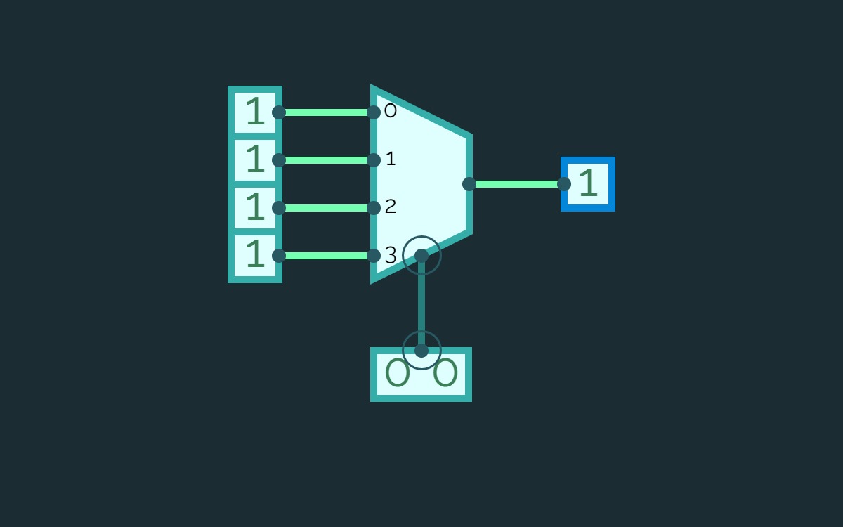
4X1 MultiplexerA 4x1 multiplexer is a device that selects one of four input signals to send to a single output.
It uses two select lines to choose which input to transmit.

EXP-7
EXP-7
2:1 Mux
2:1 Mux
Multiplexer
MultiplexerMultiplexer


