

Libed_Experiment1
Libed_Experiment1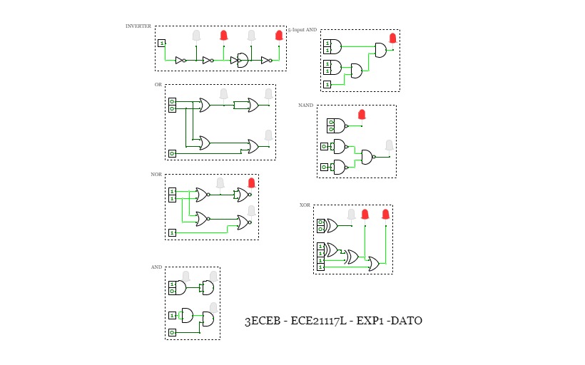
3ECEB-ECE21117L-EXP1-DATO
3ECEB-ECE21117L-EXP1-DATOExperiment 1:
Testing truth table values for logic gate combinations
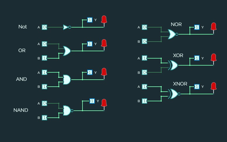
Fundamental Logic Gates
Fundamental Logic GatesFundamental Gates...
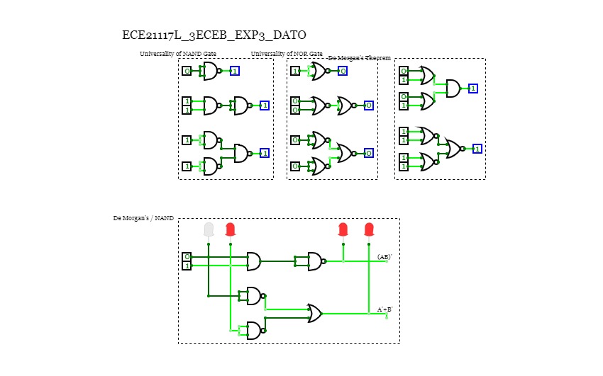
ECE21117L_3ECEB_EXP3_DATO
ECE21117L_3ECEB_EXP3_DATOExperiment 3
Universality of NOR and NAND Gates and the De Morgan's Theorem in action
Logic Gates
Logic Gates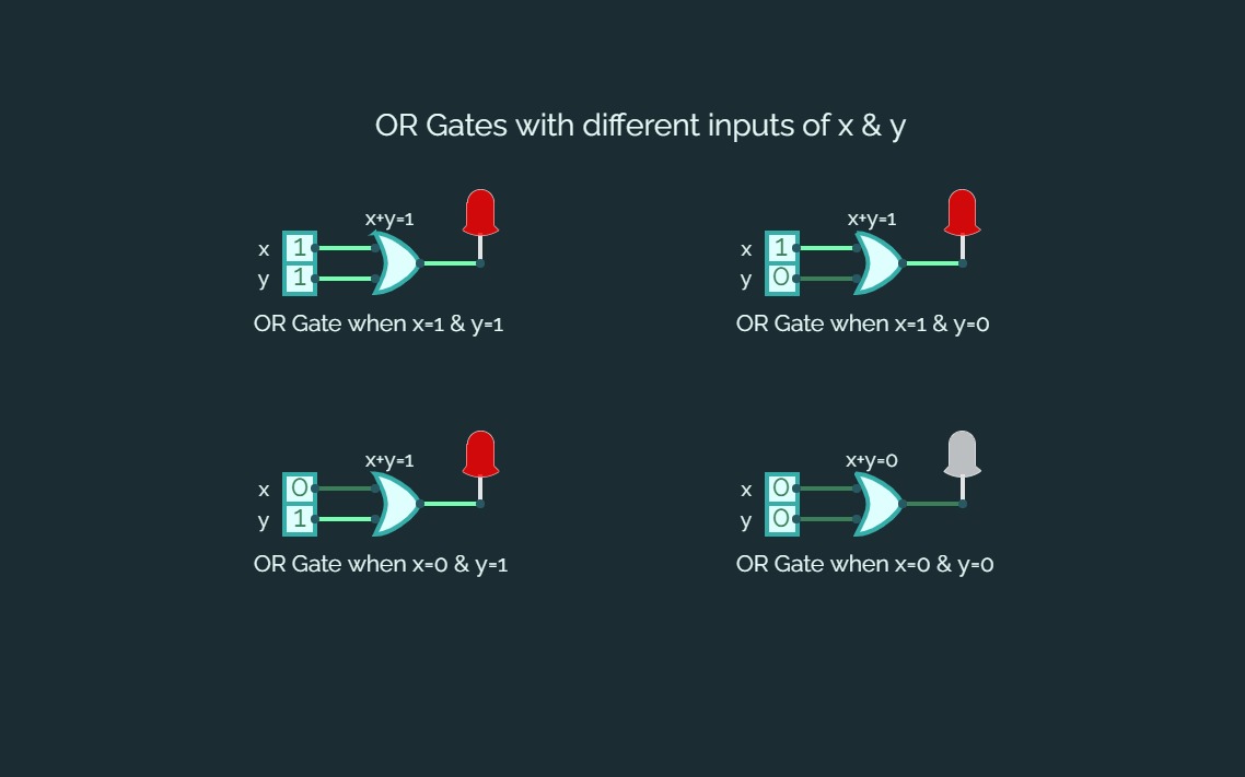
Practical 2
Practical 2Logic Gates :-
Logic gates are the basic building blocks of any digital system. It is an electronic circuit having one or more than one input and only one output. The relationship between the input and the output is based on a certain logic.
Logic gates are named as :
- AND Gate
- OR Gate
- NOR Gate
- NAND Gate
- XOR Gate
- XNOR Gate
- NOT Gate
ASSIGNMENT :
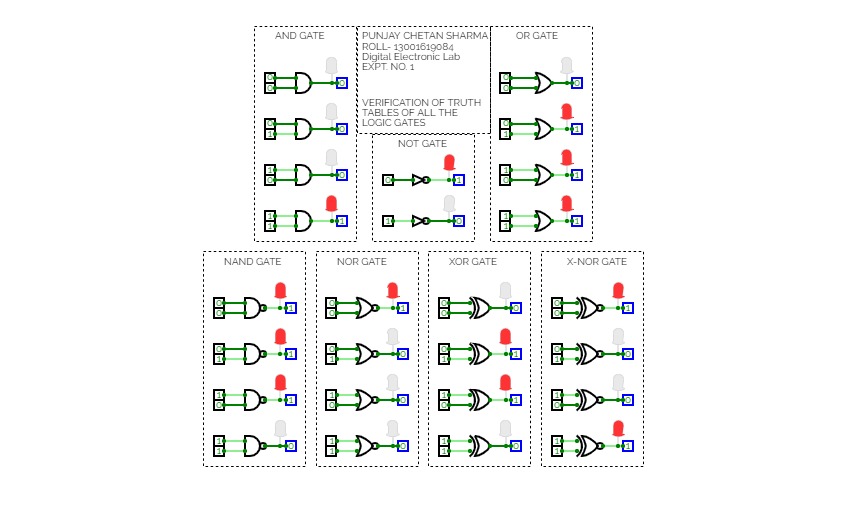
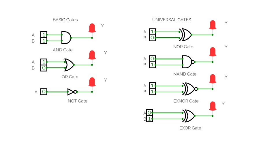
In the given assignment I have to verify all the logic gates and hence I had used digital led for it.
- Digital LED :
Digital LED is used for verification of circuit in digital electronics. It glows when circuit gives a true value and do not glows when the value is false.
In this assignment when the value will be true i.e., output will be 1 LED will glow with red color and else it will be shown in a white transparent color.
- Truth table & verification images of different gates :-
- AND Gate :


2. OR Gate :


3. NOT Gate:


4. NAND Gate :


5. NOR Gate:


6. XOR Gate:


7. XNOR Gate:


** All the diagrams and truth tables I had used above is formed using tools provided in simulator.

Lab01
Lab01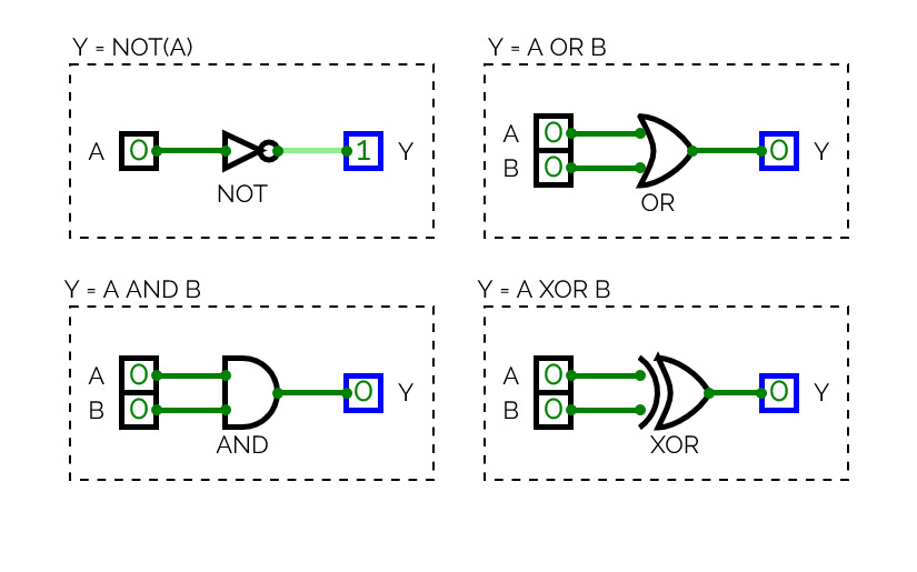
Verification of Truth Tables
Verification of Truth Tables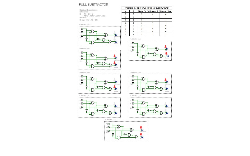
Full-Subtractor
Full-Subtractor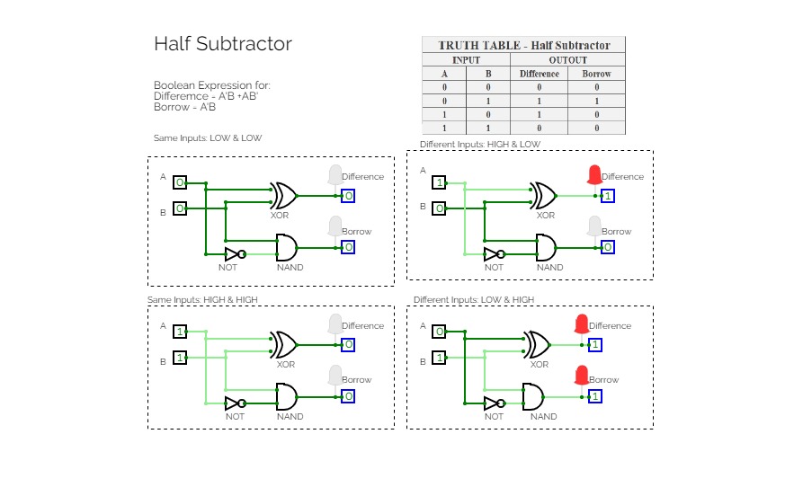
Subtractor
Subtractor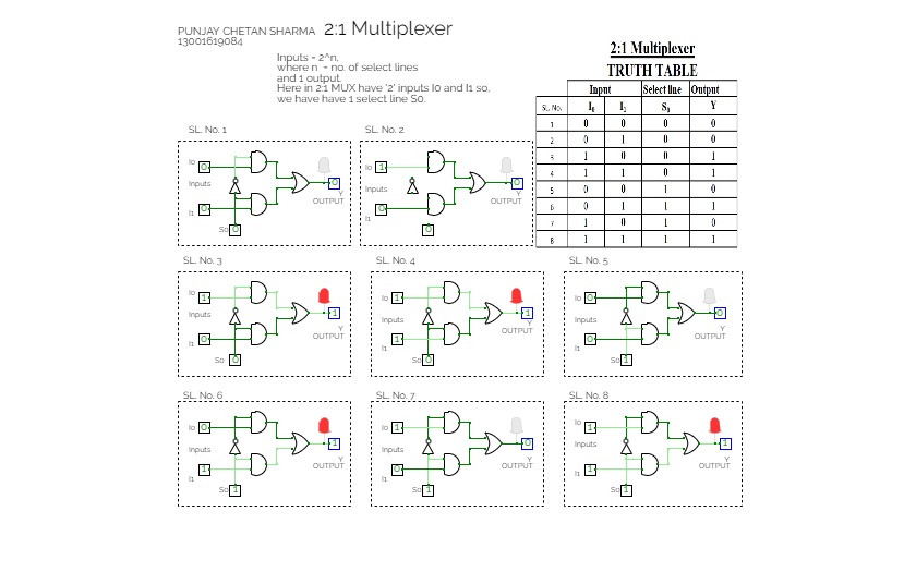
Multiplexer
Multiplexer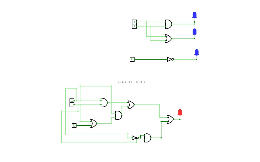
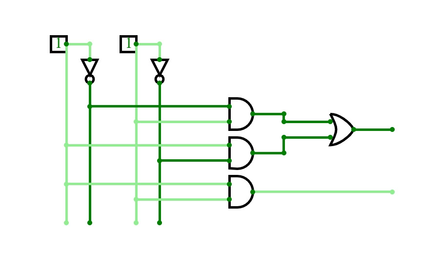
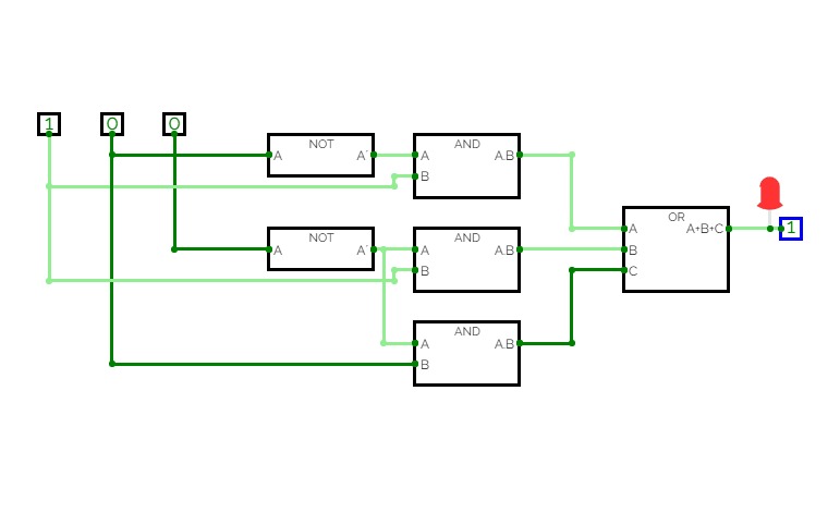
Y= AB + A(B+C) + A’B
Y= AB + A(B+C) + A’B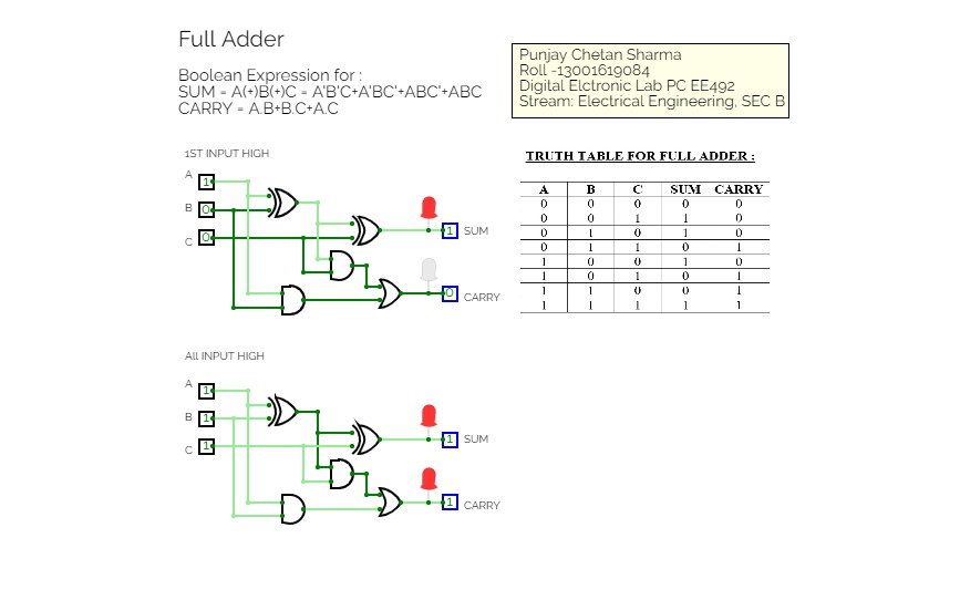
Test29.07.2021
Test29.07.2021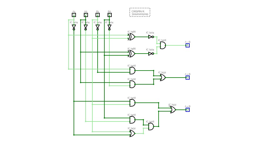
Logic Gates & Boolean Verification
Logic Gates & Boolean VerificationThis is a project for the verification of boolean laws or logic gates.
lab 2
lab 2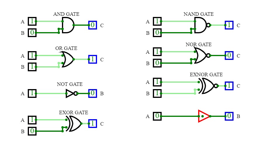
Logic Gates
Logic Gates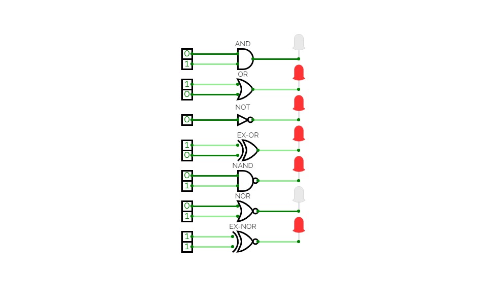
Test
Test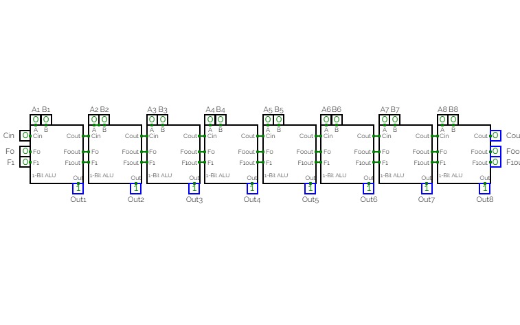
CPU ALU BUILD
CPU ALU BUILD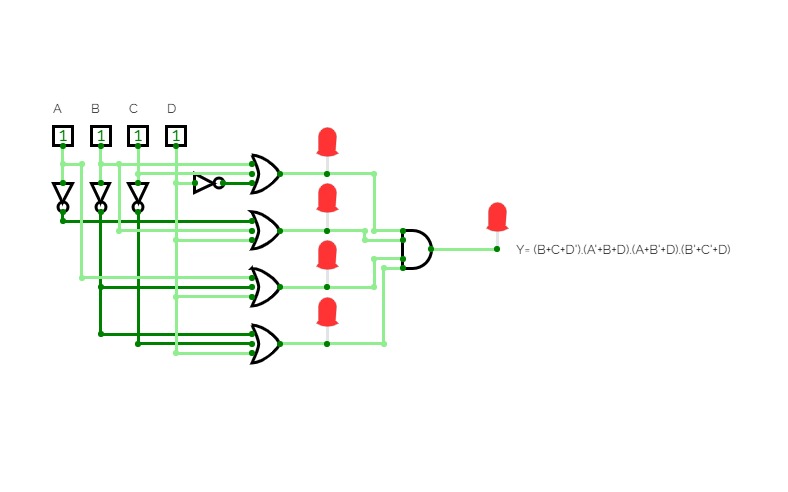
POS Eqution Circuit by Souvik Ghosh
POS Eqution Circuit by Souvik Ghosh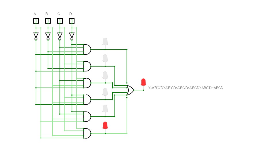
SOP Equition Circuit by Souvik Ghosh
SOP Equition Circuit by Souvik Ghosh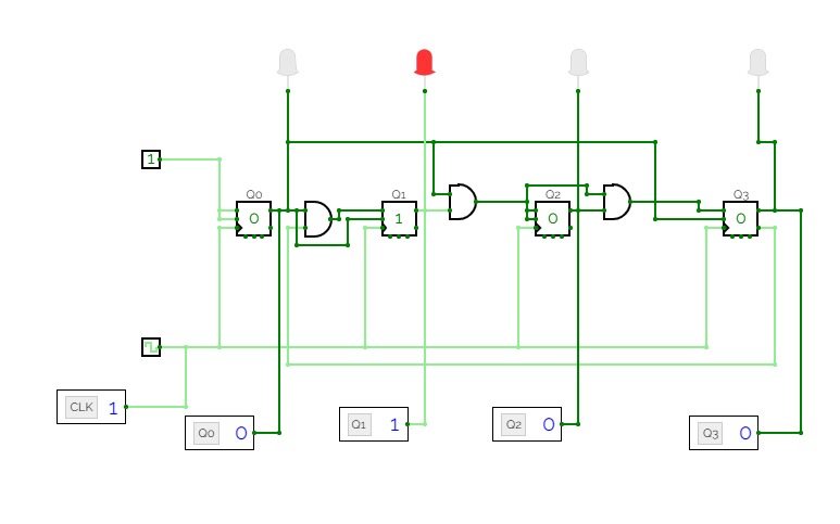
4-Bit Synchronous Decade Counter
4-Bit Synchronous Decade Counter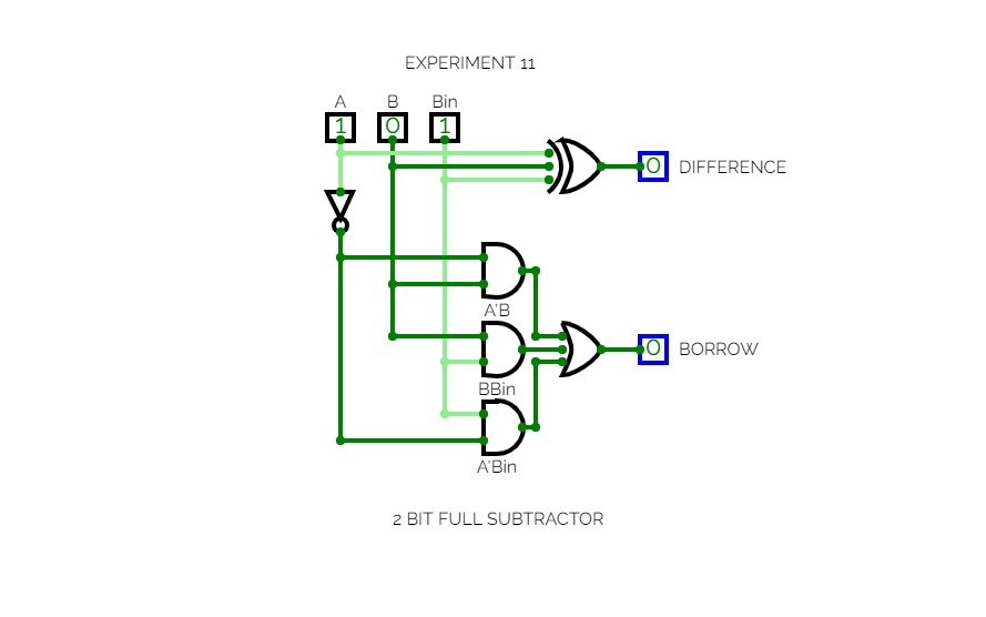

EXPERIMENT 11
EXPERIMENT 11Implementation of a Full subtractor using basic gates
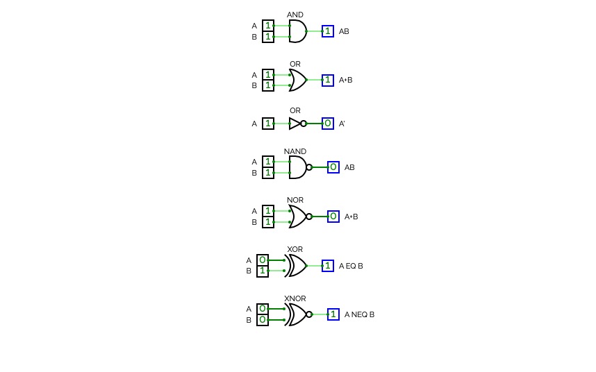
Basic Logic Gates
Basic Logic GatesLogic Gates and their Corresponding Truth Table

Experiment-3.1: De Morgan's Laws (1st Theorem) using the logic gates.
Experiment-3.1: De Morgan's Laws (1st Theorem) using the logic gates.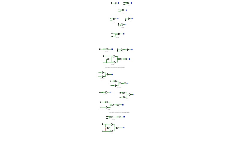

ECL Lab 1
ECL Lab 1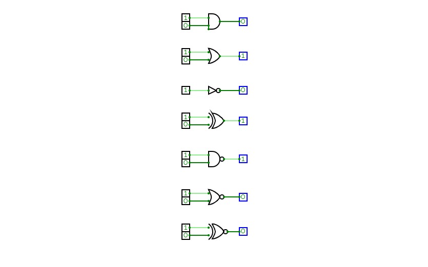
2100290130046_Experient1
2100290130046_Experient1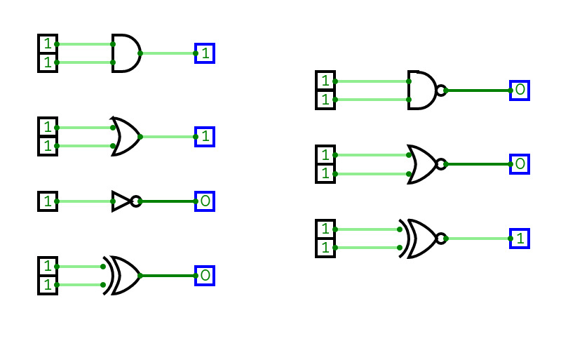

8/11/22
8/11/22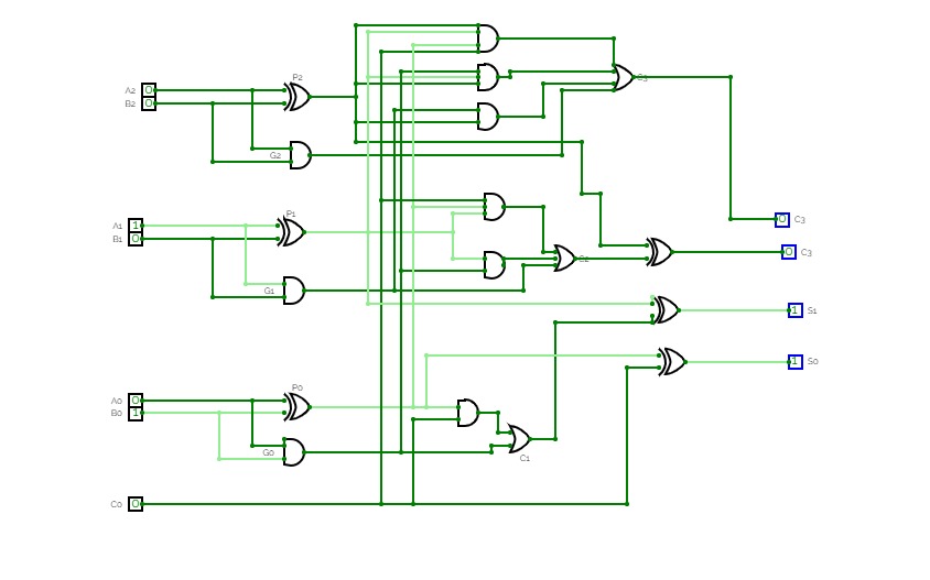

3 bit Carry Look Ahead Adder
3 bit Carry Look Ahead Addersample input
A2A1A0= 110
B2B1B0= 101
expected output
S2S1S0 = 011, C3= 1
HALF ADDER
HALF ADDER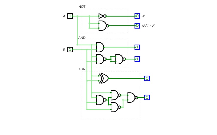

Logic Gates
Logic GatesLogic Gates
Untitled
Untitled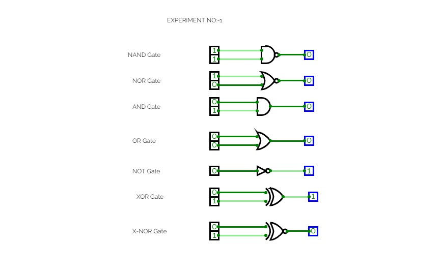
Gates Experiment 1
Gates Experiment 1
Juvenytte Pearson
Juvenytte Pearson
Untitled
Untitled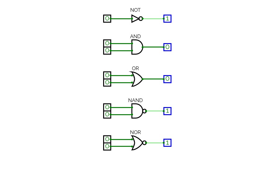

[CSCA] Logic Gates
[CSCA] Logic GatesLogic gates as discussed in the Computer Science and Computer Architectures [CSCA] course at the University of Applied Sciences CAMPUS 02, Graz, Austria.
The project features the following circuits:
- Basic Logic Gates - demonstrates behavior of the five basic logic gates. [learn more]
- Controlling Gates - demonstrates how signal propagation can be controlled by "opening" and "closing" the gates.
- Combining Gates - demonstrates how logic gates can be combined to implement an arbitrary boolean function. [learn more]
- 2-Bit Comparator - developed based on it's truth table by using the NOT, AND, and OR Gates.
- 2x2-Bit Comparator - developed by using the 2-Bit Comparator.
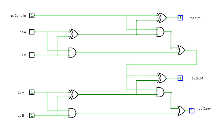
- 2-Bit Adder - developed by using the 2-Bit Comparator and basic logic gates. [learn more]
2 Full Adder
2 Full AdderMultiple Adder Gates- Pratheesh P
suchitra
suchitra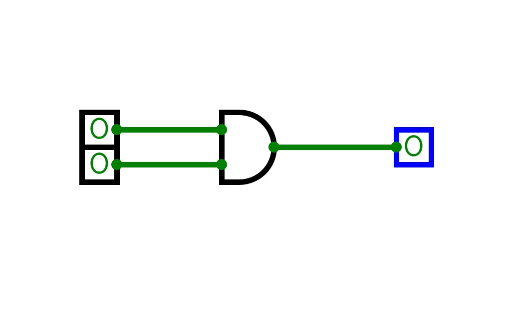
Untitled
Untitled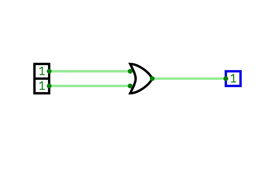
Untitled
Untitled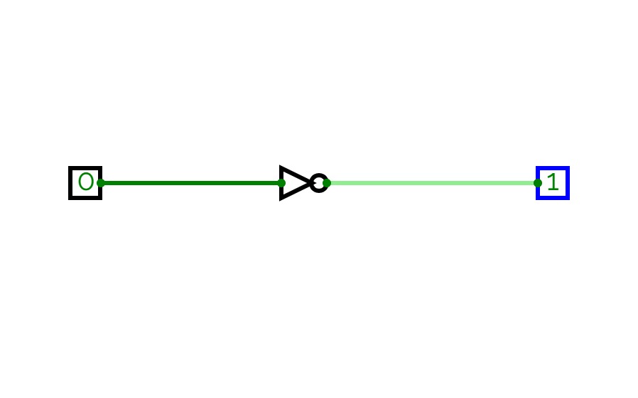
Untitled
Untitled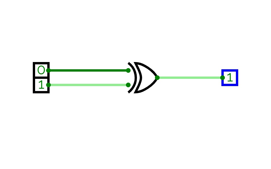
Untitled
Untitled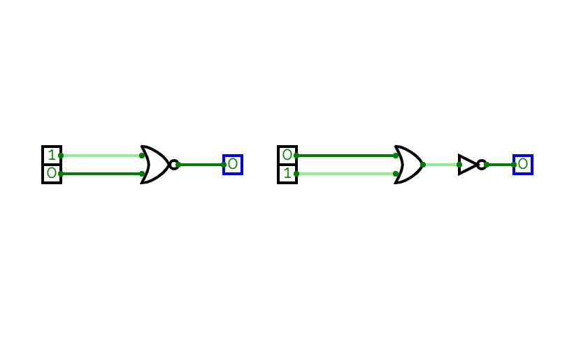
Untitled
Untitled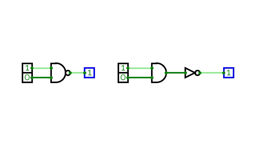
Untitled
Untitled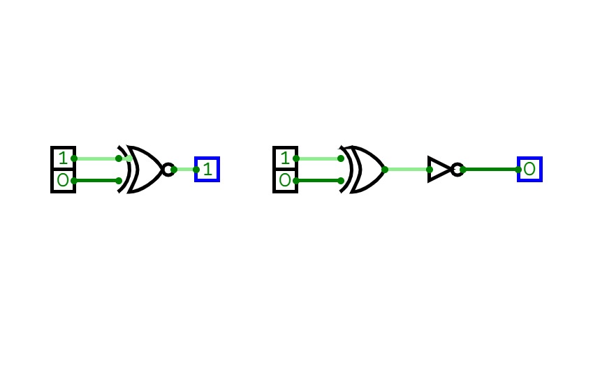
Untitled
Untitled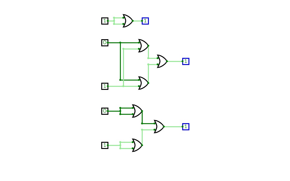
Untitled
Untitled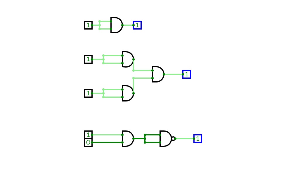
Untitled
Untitled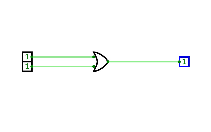
Untitled
Untitled
Untitled
Untitled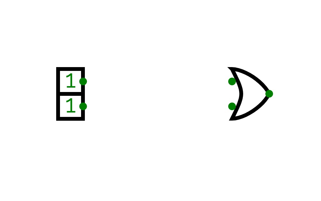
Untitled
Untitled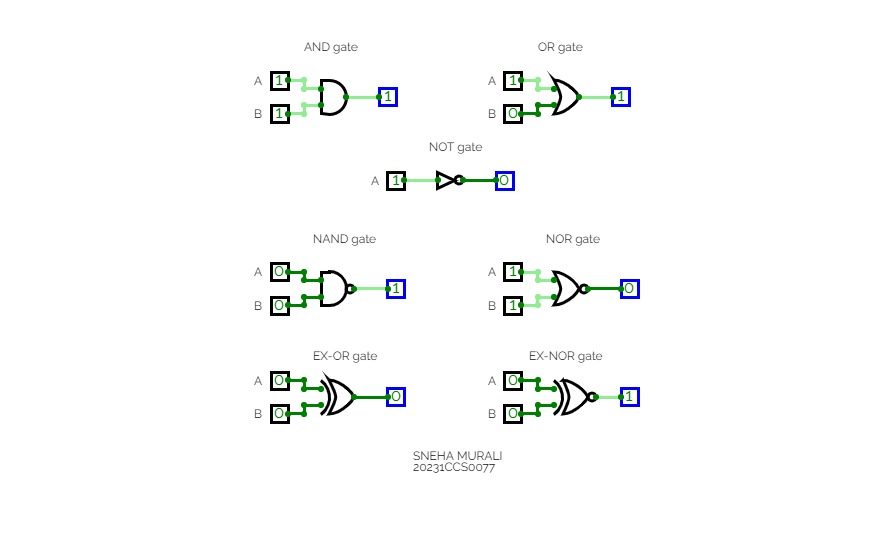
Logic gates
Logic gates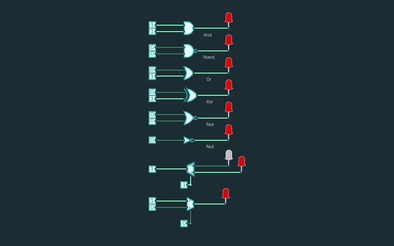
Untitled
Untitled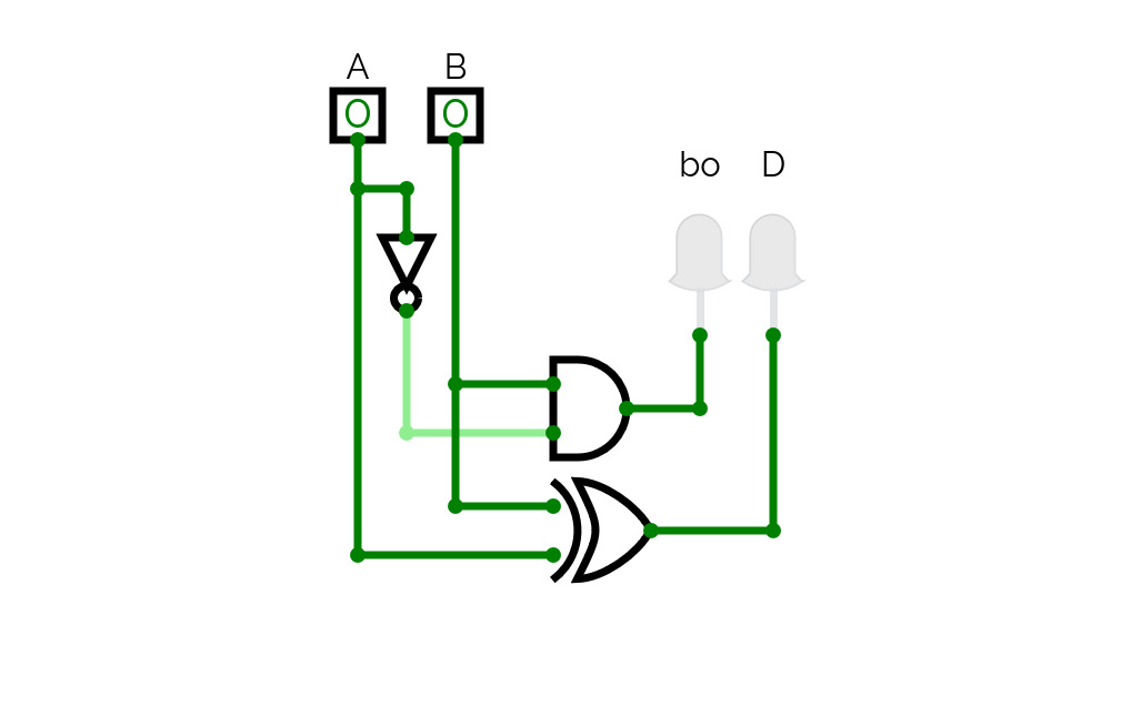

HalfSubstractor
HalfSubstractor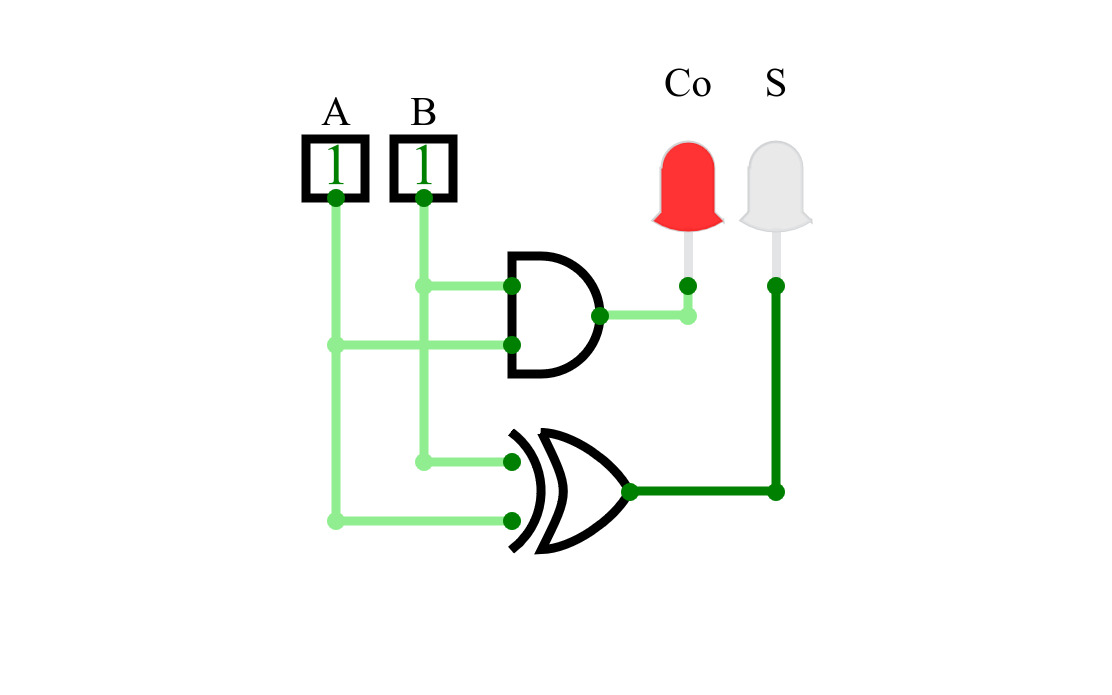
HalfAdder
HalfAdder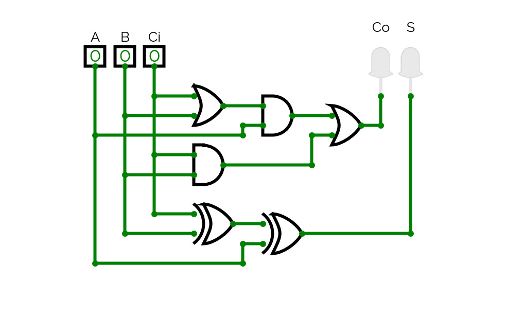
Full Adder
Full Adder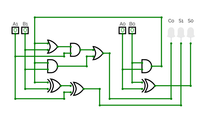
4BitsAdder
4BitsAdder
4_Bits_Adder
4_Bits_Adder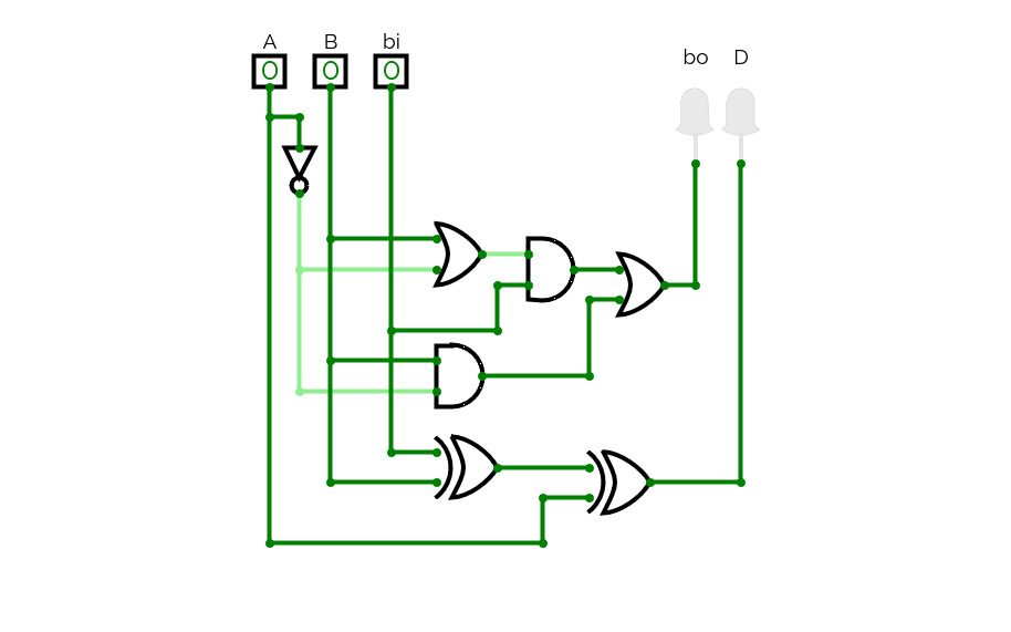
FullSubstractor
FullSubstractor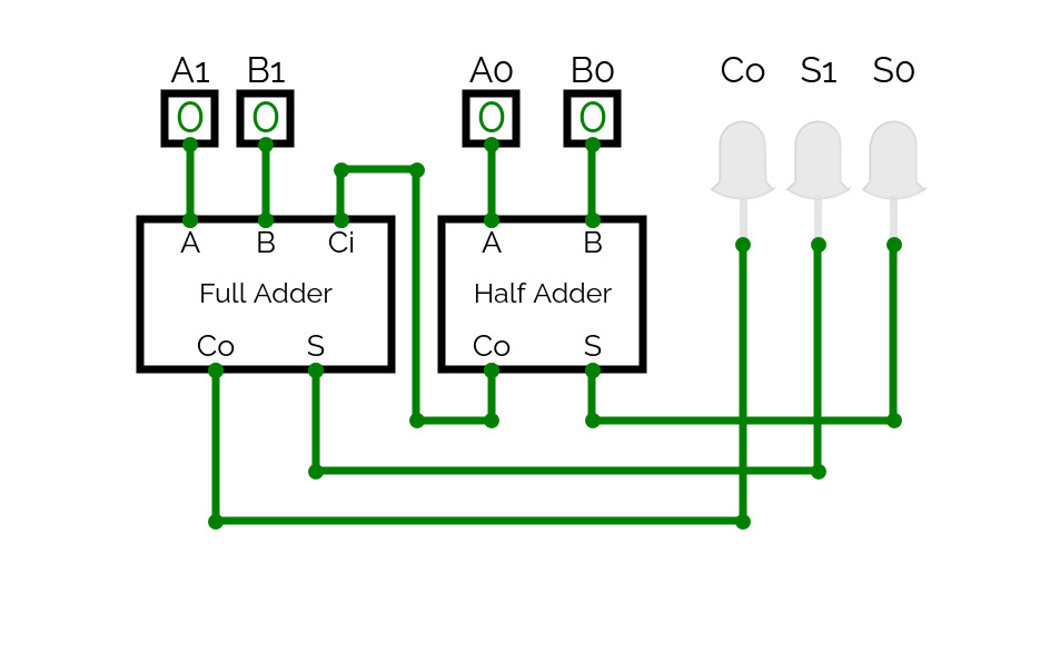
2 Bits Adder
2 Bits Adder
2 Bits Adder
2 Bits Adder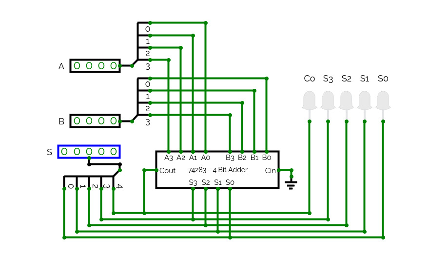
74283
74283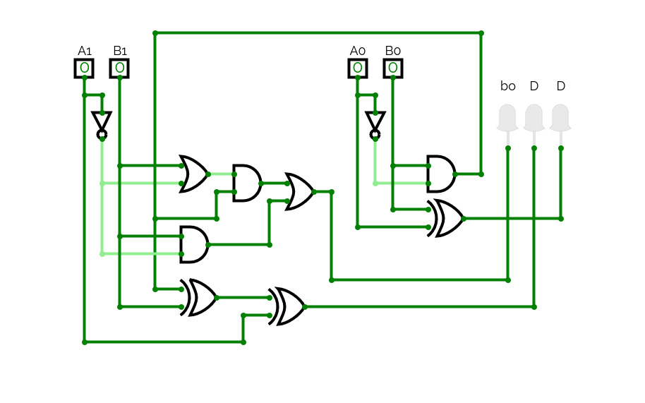
2Bits-Substractor
2Bits-Substractor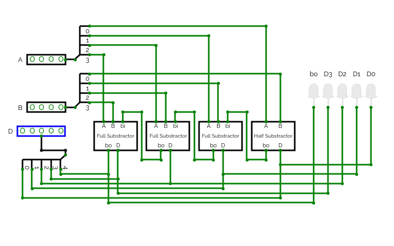
4-Bits Substractor
4-Bits Substractor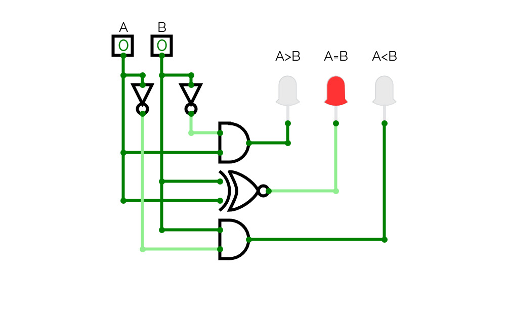
Comparador
Comparador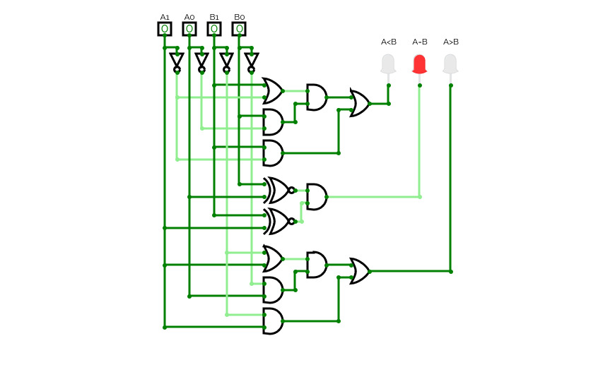
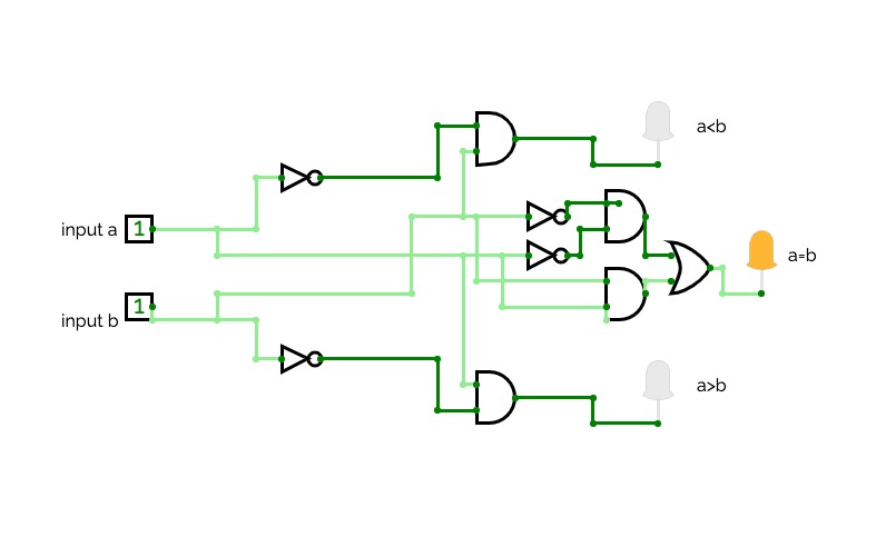
2Bits Comparator
2Bits Comparator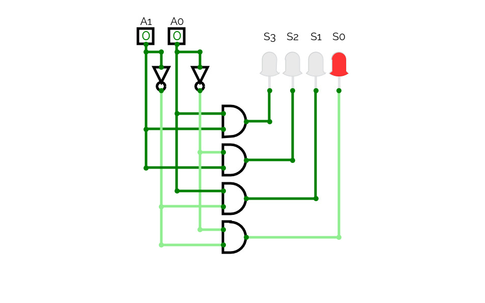
2-4 Decoder
2-4 Decoder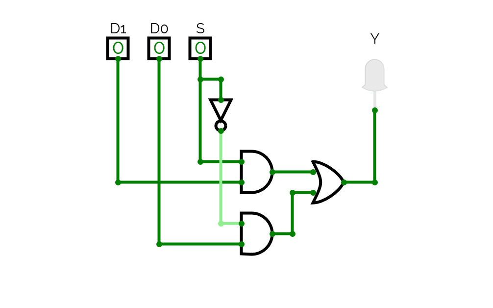
Mux 2-1
Mux 2-1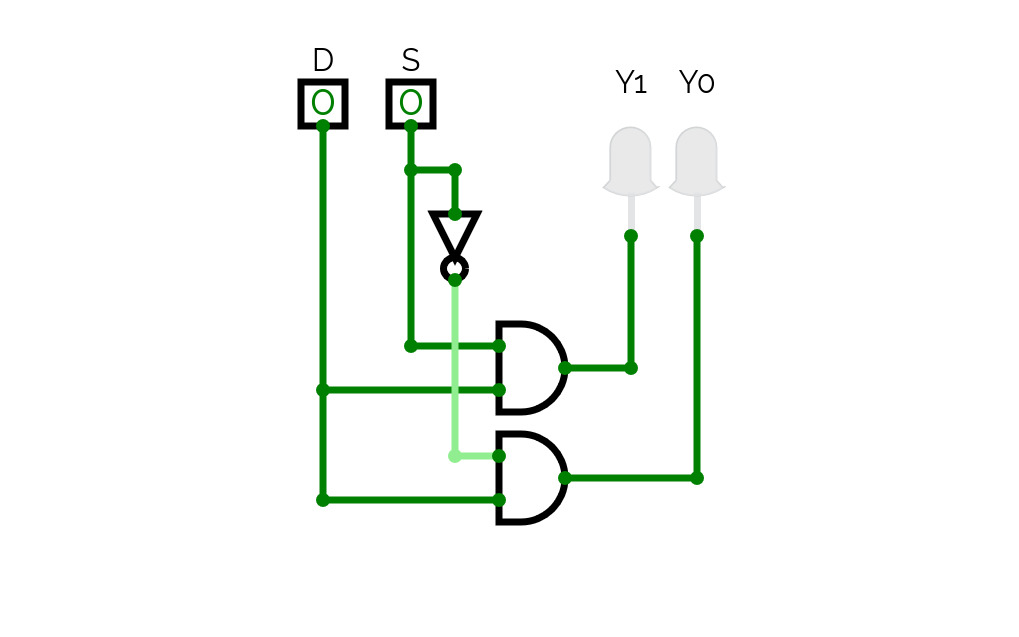
Demux 1:2
Demux 1:2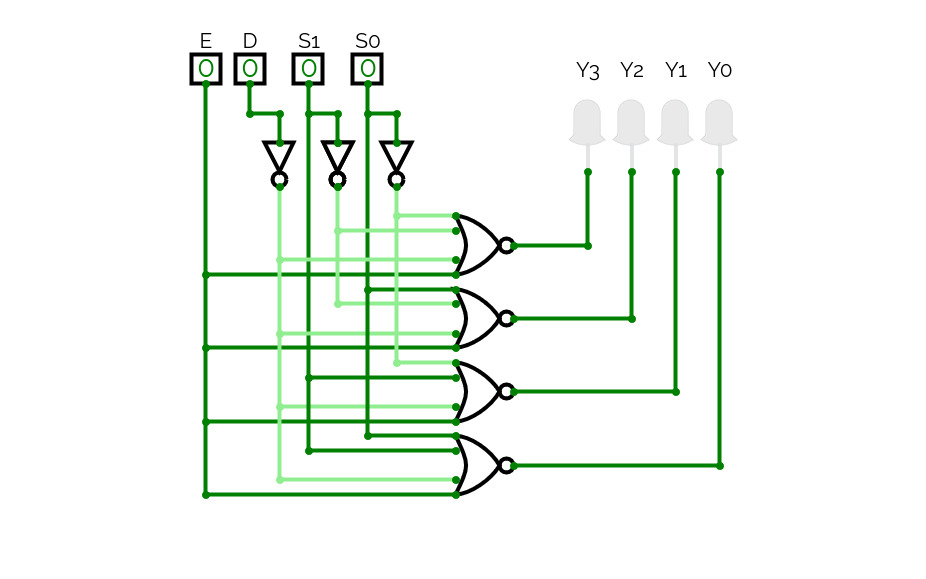
Demux 1-4
Demux 1-4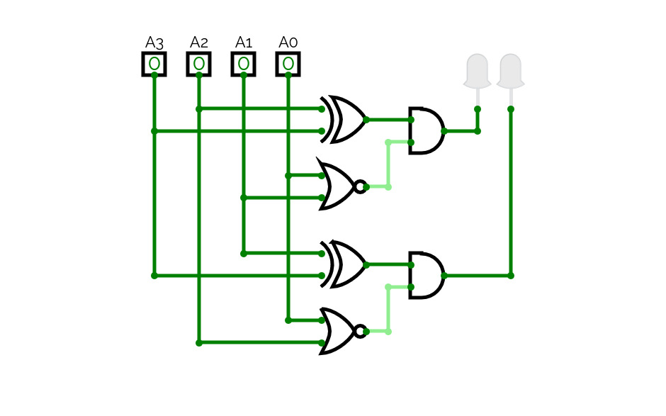
4-2 Coder
4-2 Coder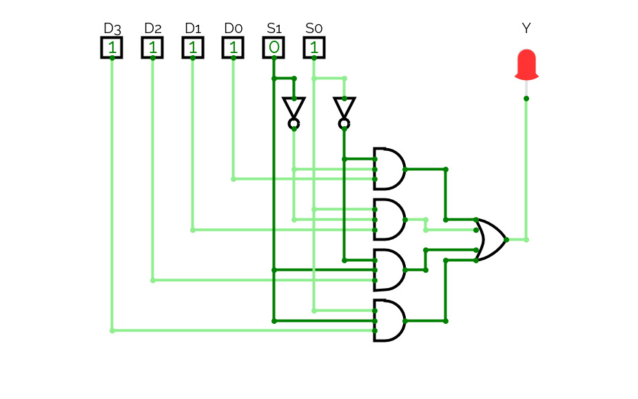
Mux 4-1
Mux 4-1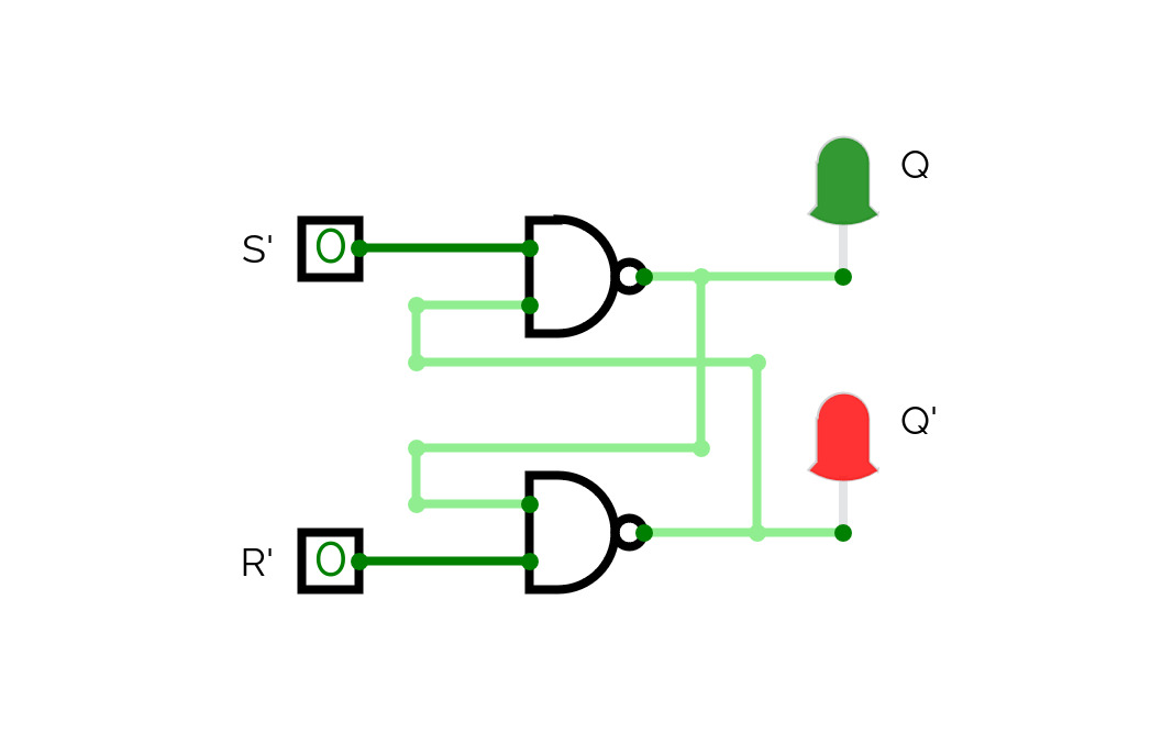
Latch SR NAND
Latch SR NAND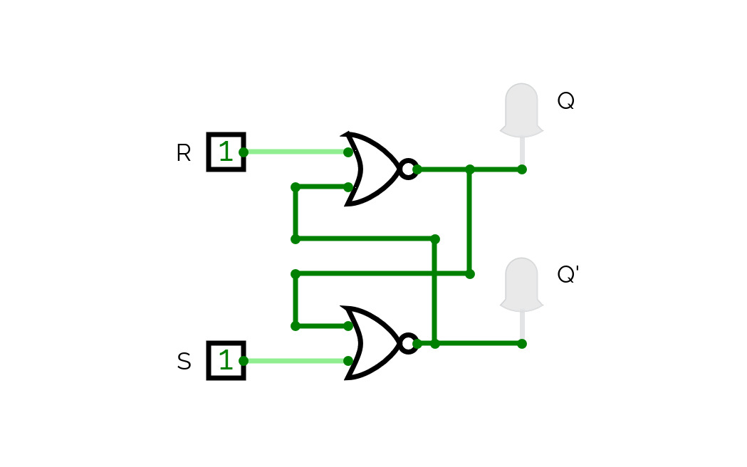
Latch SR NOR
Latch SR NOR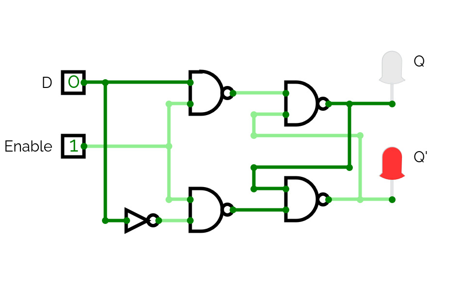
Latch D NAND Enable
Latch D NAND Enable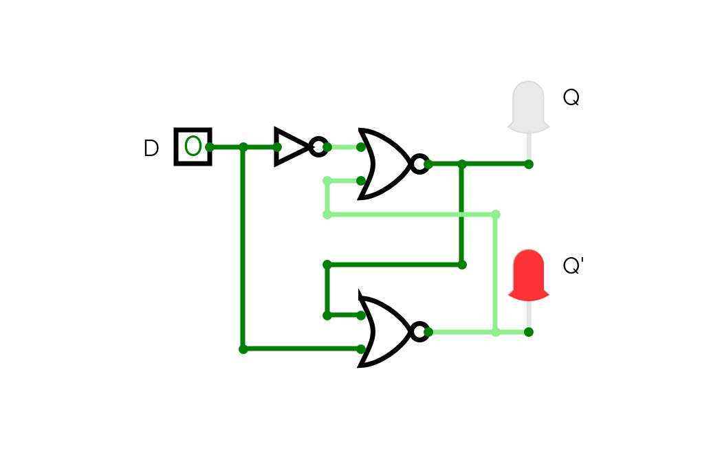
Latch D NOR
Latch D NOR
Latch JK NOR
Latch JK NOR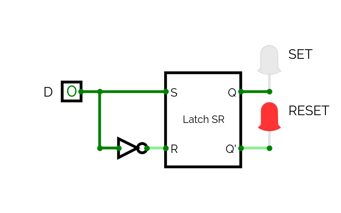
Latch D NOR Gates
Latch D NOR Gates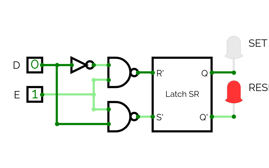
Latch D Enable NAND Gates
Latch D Enable NAND Gates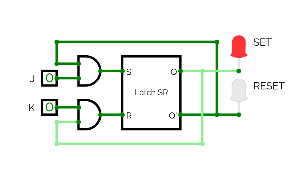
Latch JK NOR Gates
Latch JK NOR Gates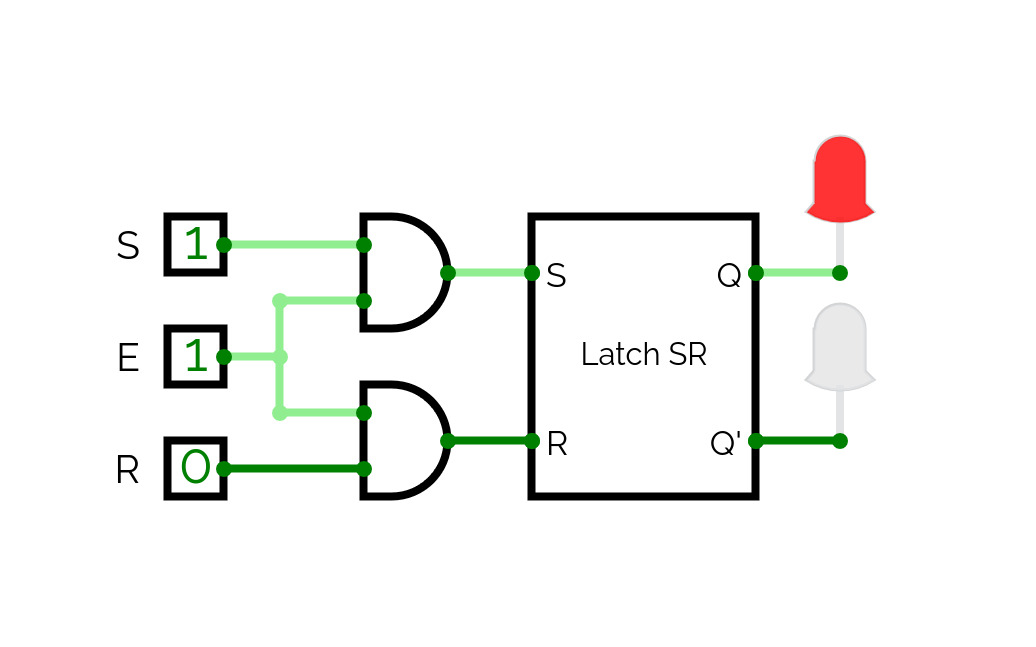
Latch SR Enable NOR
Latch SR Enable NOR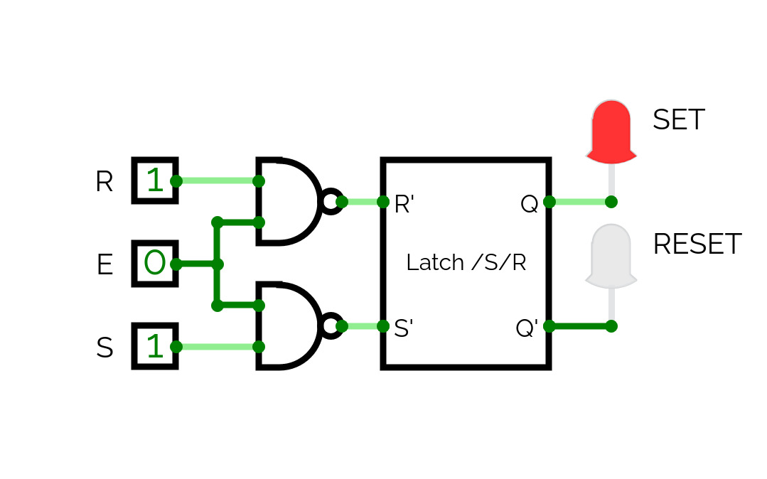
Latch SR Enable NAND
Latch SR Enable NAND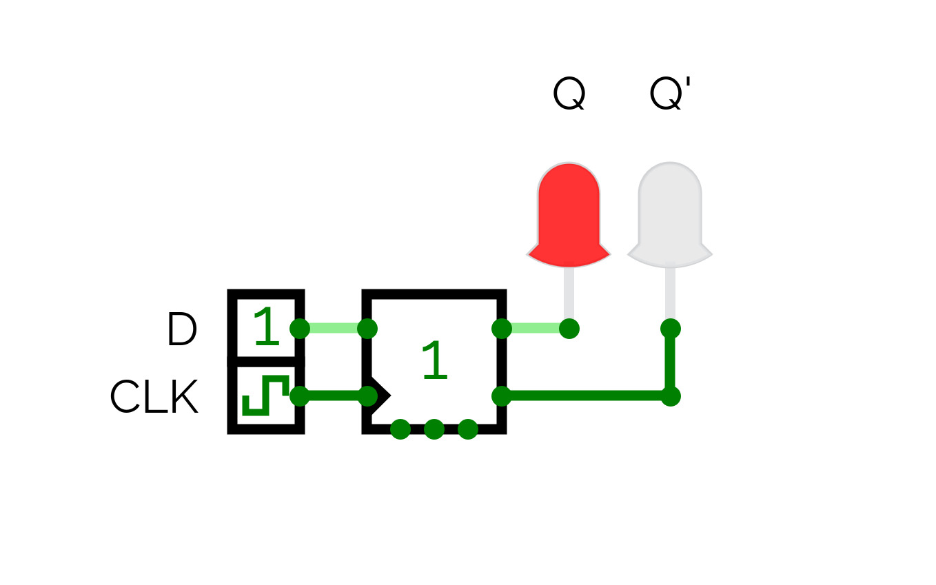
Flip Flop D UP
Flip Flop D UP
ECE351 EXPERIMENT 2 GROUP 9 EE1124D
ECE351 EXPERIMENT 2 GROUP 9 EE1124DBasic Logic Gates

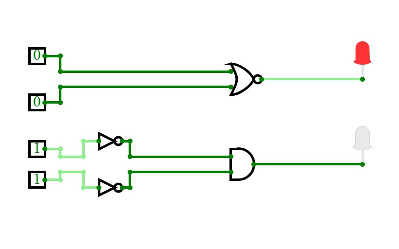
Beginner Logic Gates and Circuits
Beginner Logic Gates and CircuitsA handful of fundamental circuits exploring logic gates

XOR
XORXOR Created With Only NANDS

NOR Gate With NANDs
NOR Gate With NANDsNor gate created only with nand gates

AND gate with NANDs
AND gate with NANDsAND gate created only with NANDS

NOT gate with NAND
NOT gate with NANDNOT gate made with only NAND gates

OR gate with NANDs
OR gate with NANDsOR Gate created only with NAND gates

Full Adder
Full AdderThis is a simple digital logic circuit diagram for full adder using A,B and Cin as input and then Sum and Cout as output.

Verification of logic gates
Verification of logic gates
4 Bit Full Adder/Subtractor
4 Bit Full Adder/SubtractorA 4-bit full adder/subtractor is a circuit that adds or subtracts two 4-bit binary numbers.
It uses a control signal to choose between addition and subtraction.
The circuit gives a 4-bit result and a carry or borrow bit.

E
E
Logic Gates
Logic Gates
Bs-it 09
Bs-it 09"This project demonstrates the basic functionality of logic gates (AND, OR, NOT) using a digital circuit simulation. It is designed to help understand the principles of Digital Logic Design (DLD) and the relationship between inputs and outputs in logic circuits."


