Assignment1(2)
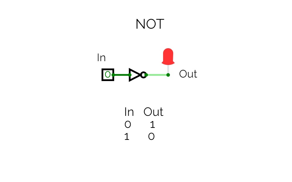
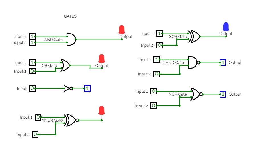
Assignment1(2)The NOT gate has 1 input (In) and 1 output (Out).
The input can be 0 or 1, and the users can change (0 to 1 or 1 to 0) the value, with a click on the small box of the input.
The output (Out) has connected a red led to signal if the output is 1 or 0 (1 is red led, 0 is led without color).
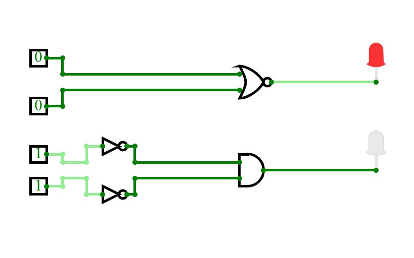
Experiment-3.1: De Morgan's Laws (1st Theorem) using the logic gates.
Experiment-3.1: De Morgan's Laws (1st Theorem) using the logic gates.Bs-it 09
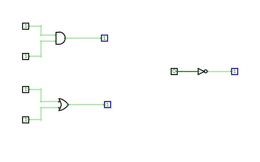
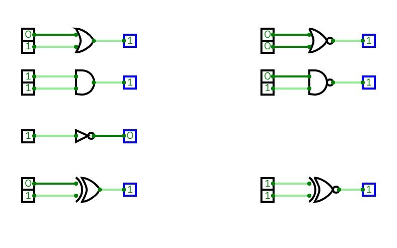
Bs-it 09"This project demonstrates the basic functionality of logic gates (AND, OR, NOT) using a digital circuit simulation. It is designed to help understand the principles of Digital Logic Design (DLD) and the relationship between inputs and outputs in logic circuits."
Password Checker System
Password Checker SystemMaking a Security Project which will help in making password secure and it will work properly. This project will match the the user password with the saved password and if you its match it will be able for log in other wise it will be not able for log in.


