
Demultiplexer
Demultiplexer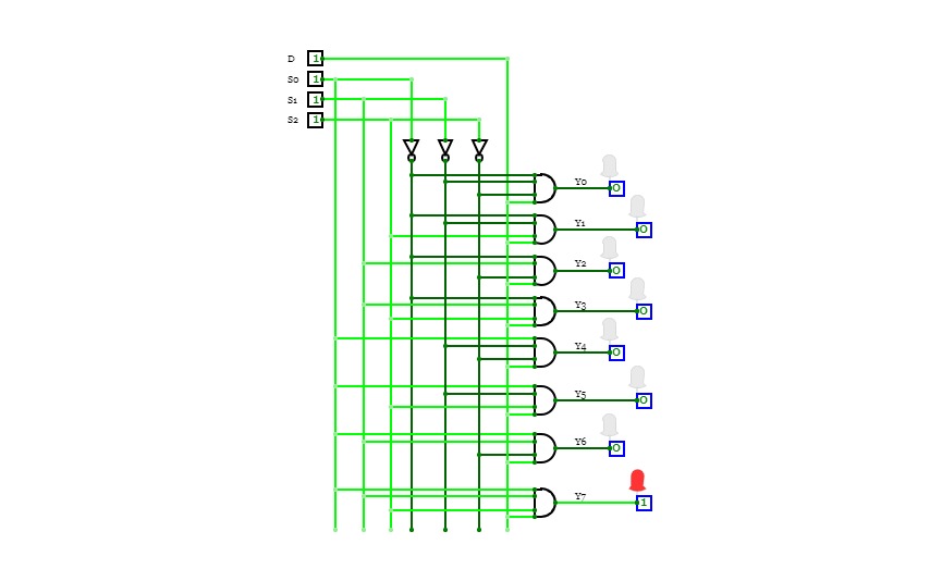

1X8 Demux
1X8 Demux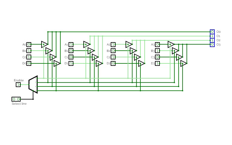
Exp-6 To simulate a common bus using tri-state buffer using demux
Exp-6 To simulate a common bus using tri-state buffer using demux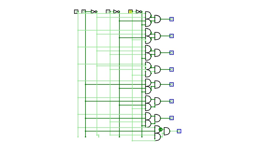

1:8 demux
1:8 demux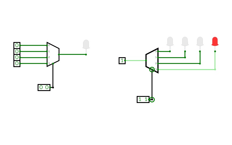
MUX DEMUX
MUX DEMUX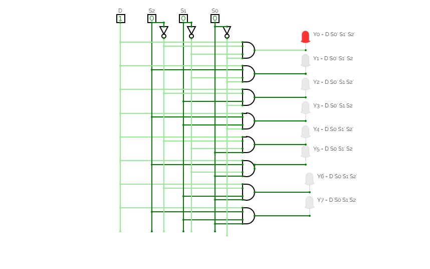
Internal GATE diagram of Demux
Internal GATE diagram of Demux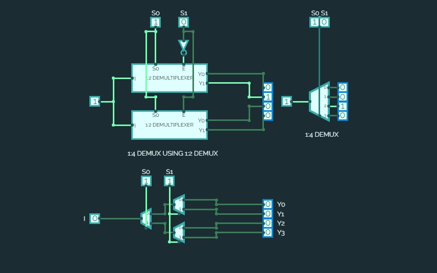

EXPERIMENT 15B
EXPERIMENT 15BImplementation of a DEMUX using Basic Gates and other DEMUX'es
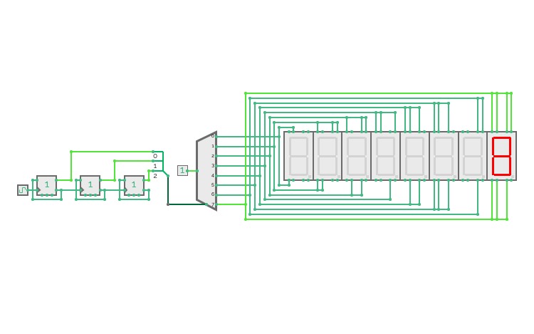
DEMUX Counter
DEMUX Counter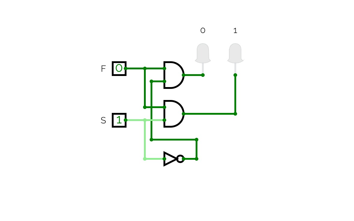
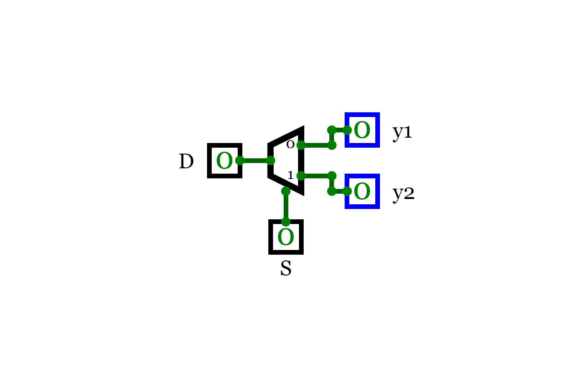
2 Channel Demultiplexer
2 Channel Demultiplexer
4 Channel Demultiplexer
4 Channel Demultiplexer
8 Channel Demultiplexer
8 Channel Demultiplexer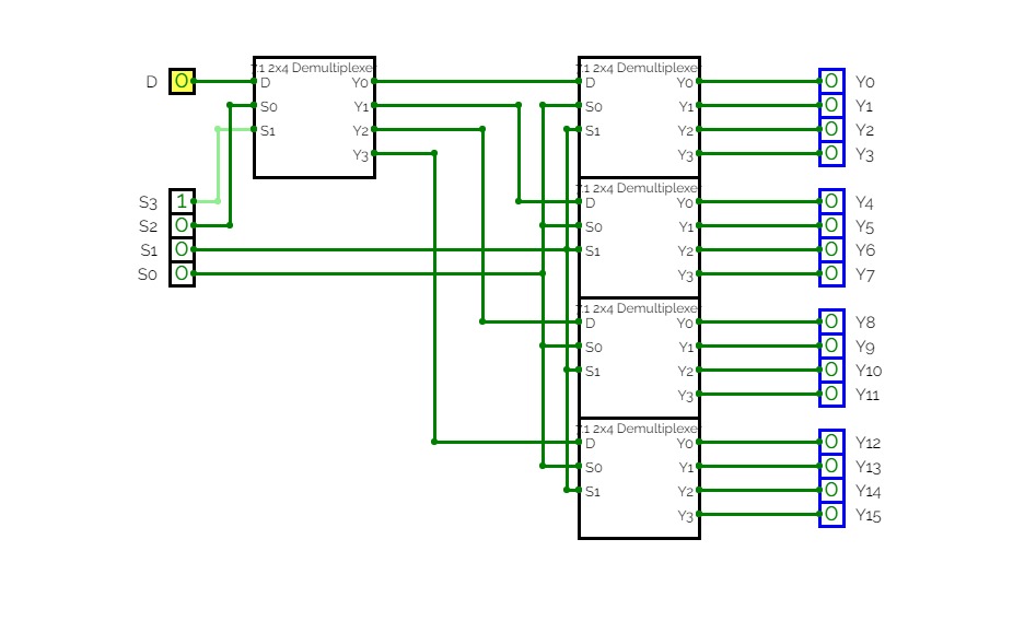
Lab 7: Demultiplexer
Lab 7: Demultiplexer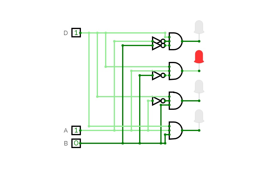
Demultiplexer
Demultiplexer
Program 4 - DeMultiplexer
Program 4 - DeMultiplexer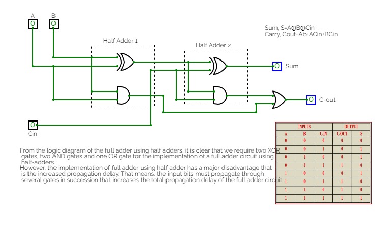

LAB PROJECT
LAB PROJECTClass lab project

Mux/Demux
Mux/Demux

Demultiplexer
DemultiplexerSomething lol

Mux and Demux
Mux and Demux
Encoder, Decoder, Multiplexer, Demultiplexer
Encoder, Decoder, Multiplexer, Demultiplexer
Aron Sorimuda Johanes Pasaribu_24060124130086
Aron Sorimuda Johanes Pasaribu_24060124130086Praktikum 4 Dasar Sistem A1 Informatika 2024
Tugas: Membuat Encoder 4x2, Subcircuit Encoder, Priority Encoder, Decoder 2x4, Latihan nomor 4a, 4b, dan 5


