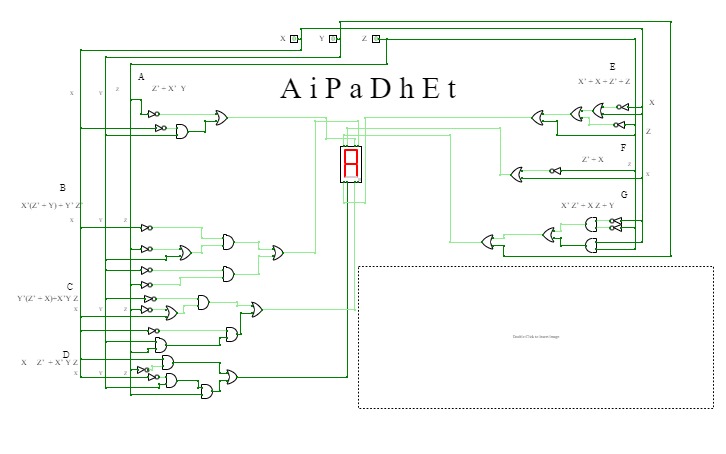
Spectrogram MK 2
Spectrogram MK 2Spectrogram
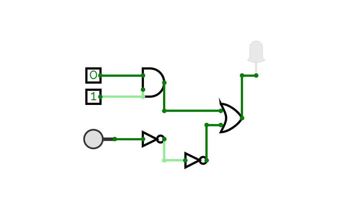
Spectrogram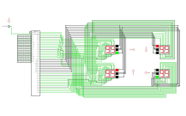
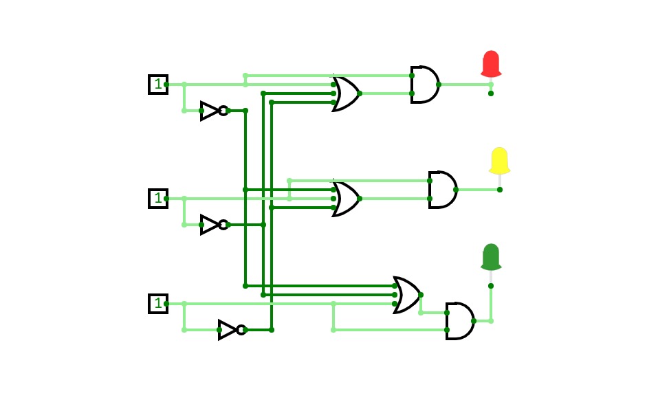
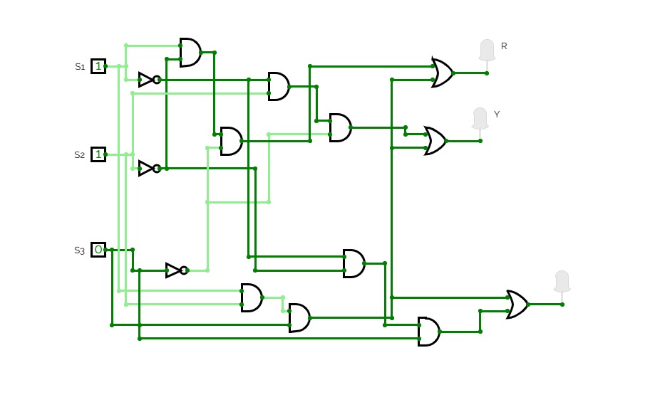
SEMÁFORO/TRAFFIC LIGHT
SEMÁFORO/TRAFFIC LIGHT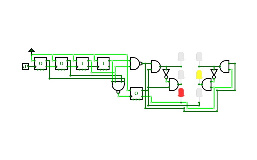
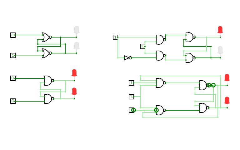
Traffic lights/Semaforo
Traffic lights/SemaforoSimulation of traffic lights created by using 4 bits counter that use T FipFlops.
Simulación de un semáforo creado con un contador de 4 bits que usa FlipFlops de tipo T
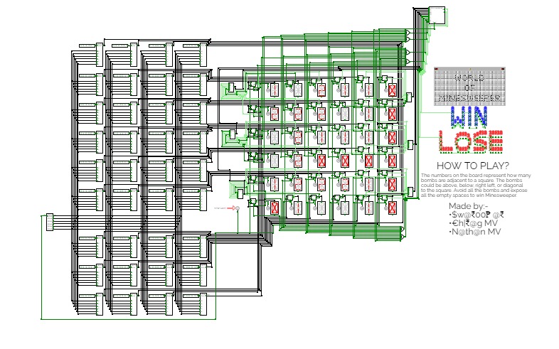
MineSweeper
MineSweeperMinesweeper: The game
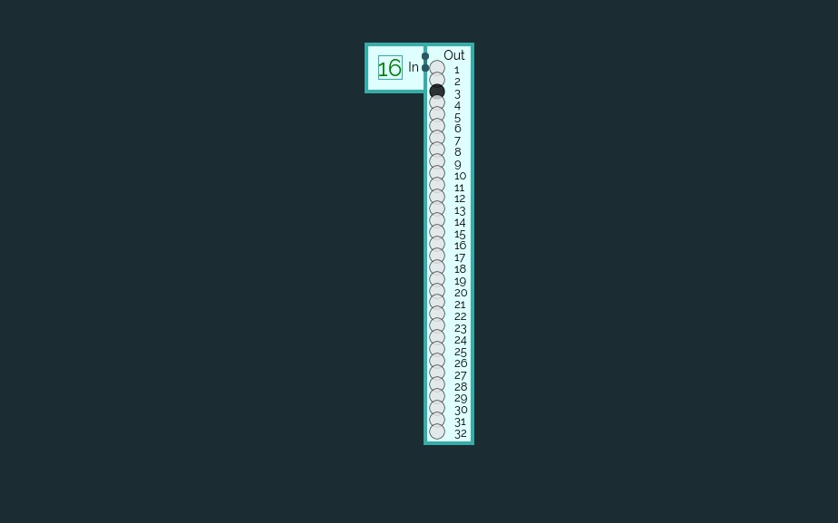
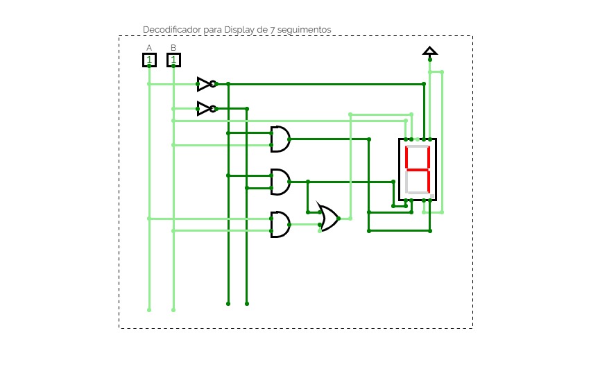
7 segment LED : Number display
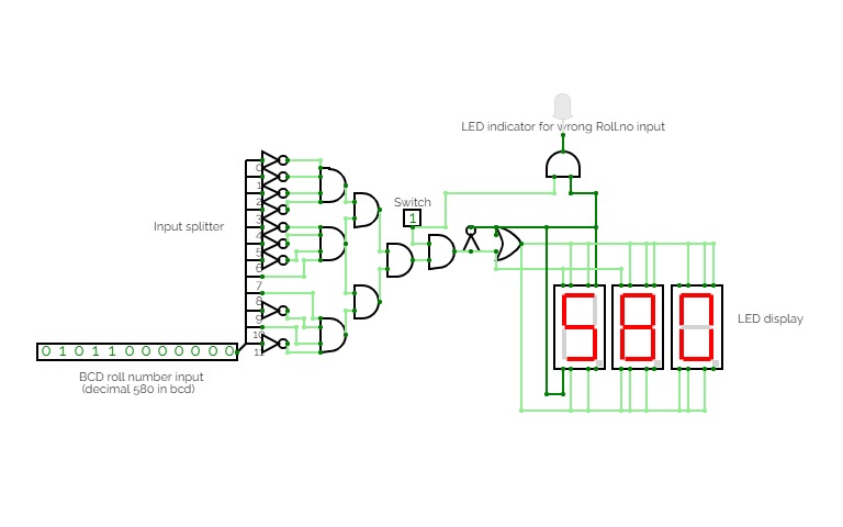
7 segment LED : Number displayThis is an Interactive project where you input a number in binary format. You will get an output of the same number in decimal on the 7-segment led display. (if that number = 580. That's my roll no so that's why :) (But you can build one for yourself :)
It will give output only when the input number = 580. Otherwise, it glows an red LED.
You can change this to any number yourself. Just change the connections yourself to the LED and 7 segment display
The input is 12 bits which would support numbers up to 4095. You can increase the bit length of the input for an even greater range.
Get an output of the number you entered on the 7-segment display.
We also have a switch to turn the display off altogether irrespective of the input given.
Submitted by
Name:- Abhinav Deshpande
Roll no.=IMT2022580
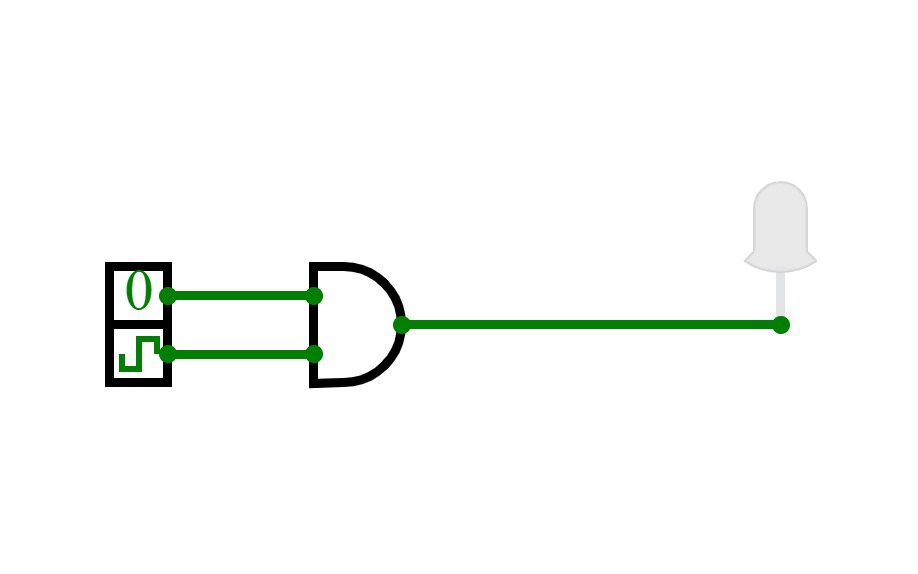
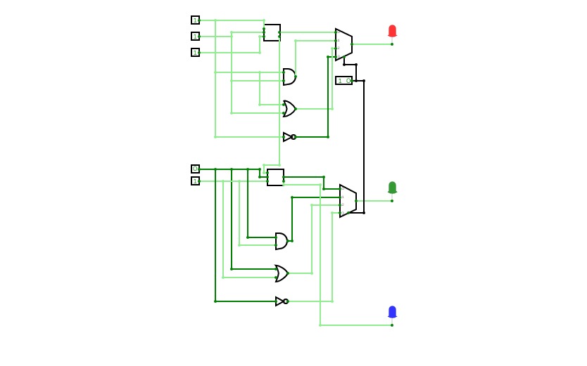
Numbers comparison circuit (2 - bit)
Numbers comparison circuit (2 - bit)ABOUT
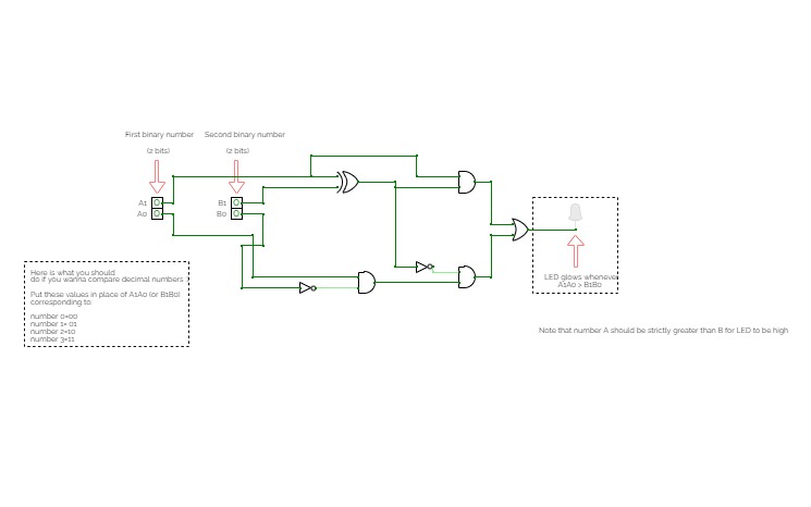
This is a very simple number comparator circuit.
You input 2 numbers and it gives an output
whether A > B (both are 2-bit numbers)
(A should be strictly greater than B)
Note that A and B are both 2-bit binary numbers. Binary meaning that they are represented with only 1s and 0s.
Remark: Even if you don't know about binary numbers, I have got you covered :)
Simply refer to the table given in the circuit to work out the input yourself.
How to use?
Change the first input number labelled as A1 A0 by toggling the input. Similarly change the second number. Observe the LED for each combination of 2 numbers.
OUTPUT
You will see an LED glowing if A > B. Otherwise, you won't see any output.
eg. If you input A1A0 as 11 and B1B0 as 10, the LED would glow.
How I came up with the circuit?
Or rather you would ask, how can I design such a circuit myself? Well I will explain. So this is called a combinational circuit. You can design your circuit by first making a truth table with inputs as your two 2-bit numbers (4 inputs in total) and thinking about output for each set of inputs. So, you would have 42 =16 total inputs in your truth table.
Next, after you have mapped your input and then your output for all those inputs, you would be solving a logical expression for output Y for a given set of 4 inputs A1A0 B1B00.
You can use any method to solve for Y. You can use a K-map based reduction or you can simply solve using basic logic identities.
Once you get an expression (expression means something like this say (for eg. this is not what you may get) Y= A1.B1'+B1'B0'+...)
, you would then realize the circuit using logic gates. Just as I have done.
What you can try to do afterwards
Increase the input to 3-bits , 4-bits and so on...