Estudiar FSM
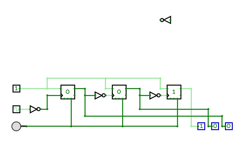
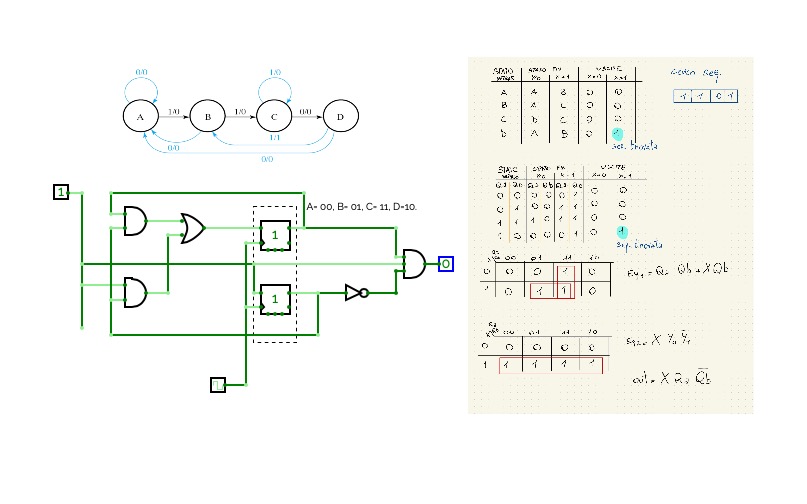
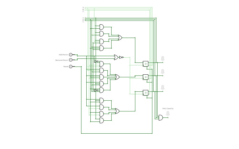
Estudiar FSMThis is just a practice machine for the FSM test and sequential logic
Proyecto Digital # 1
Proyecto Digital # 1FSM
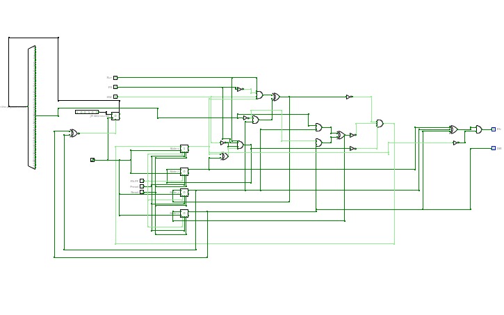
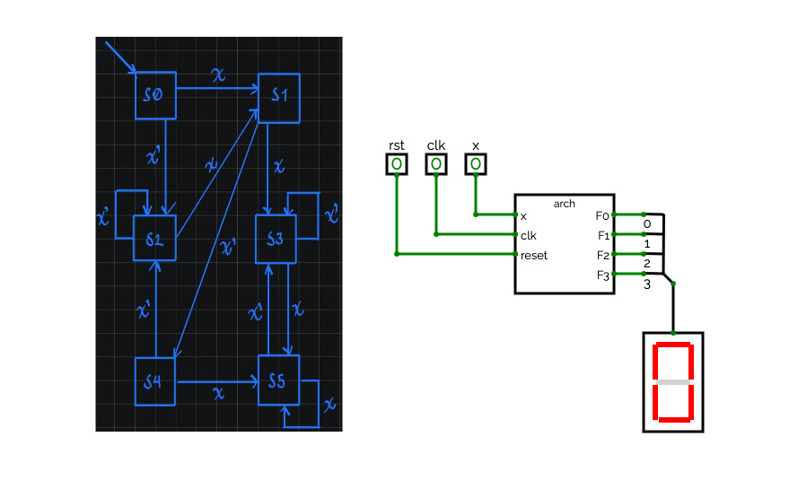
FSMGroup C EE-184 Project 3. This circuit is a state machine built-in hardware used to control a stepper motor by interfacing with a motor driver. The inputs are Run, Handwave, and Free Range. In Free Range mode the motor will spin in one direction constantly. When switched to Hand wave mode the motor will move 36 steps clockwise and then 36 steps back counterclockwise. Run must be active to enter either of these states. If Run is deactivated while Handwave is active the motor will finish its 36 step cycle and stop.
SequentialCircuits_Tutorials
SequentialCircuits_TutorialsDigital Logic Design, Sequential. Combinational Logic, ALU, CPU, Finite State Machine, FSM, State Diagram, State Table, Flip Flops, Registers, Counters
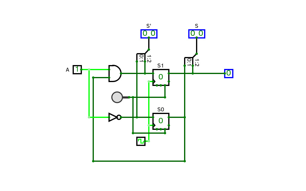
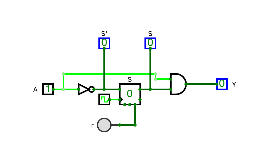
sequence detector
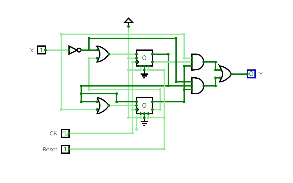
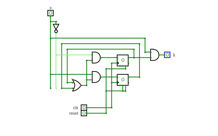
sequence detectorMoore and Mealy machines detection the binary sequence 01.
Encoding states: one-hot.
WashingMachineArthur
WashingMachineArthurcs231
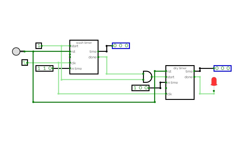
cs231The washing machine will have two states: washing which required a counter
that will stop when it reaches number 6 and drying which required a counter that
will stop when it reaches number 4.
The controller should have 2 inputs a start and a reset. When the start input is
disabled (set to 0), both washer and dryer should stop. When the start input is
enabled (set to 1), the washing cycle should start counting from 0 to 6 then stop;
after that the dryer cycle should start counting from 0 to 4, i.e., the drying cycle
will start after the washing cycle finish.
The reset button we reset both counters.
The final circuit will look something like this
JK FSM
JK FSMFSM Vending Circuit
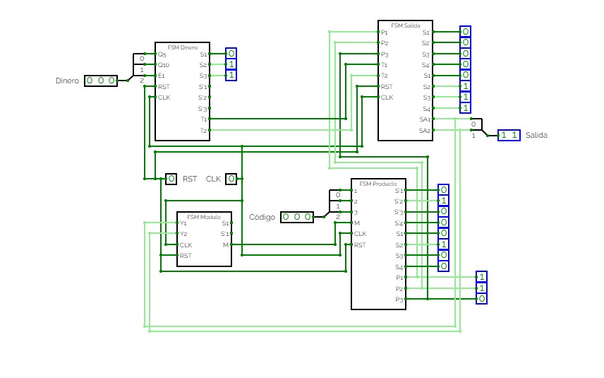
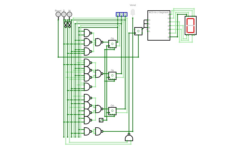
FSM Vending CircuitImplementation of a FSM for a vending machine with the following specifications:
• The machine takes nickels and dimes.
• There is a single coin slot, and a sensor detects the type of coin then asserts one of two signals, N for nickel, and D for dime.
• The machine dispenses candy once it receives 25 cents.
• The machine will not return change.
Includes the following I/Os:
a. Two inputs N and D to the circuit
b. A reset input connected to the asynchronous clear
c. A seven segment display which shows the current number of coins (button presses)
d. A single LED as output to indicate when the “vend” condition is true.
Pedestrian traffic light
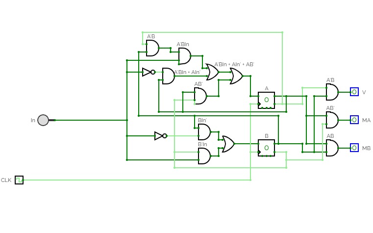
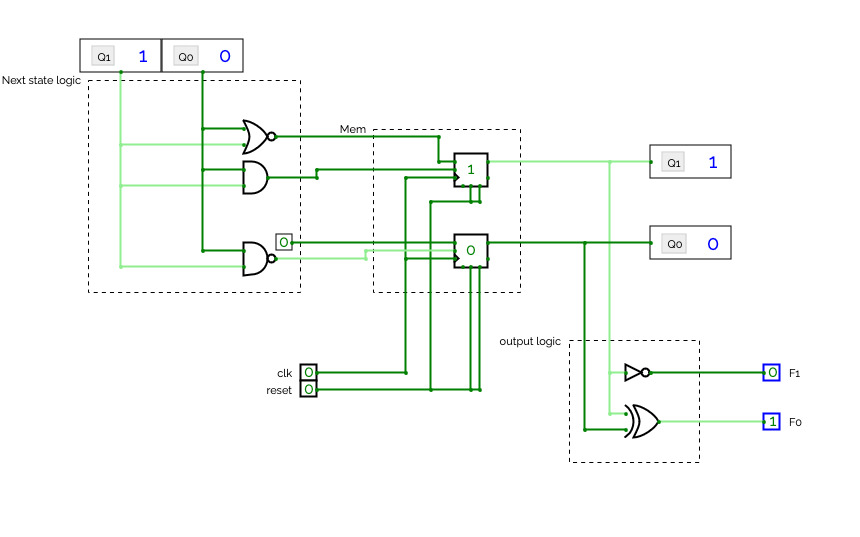
Pedestrian traffic lightThis project simulates a pedestrian traffic light based the state of the main traffic light:
-
When the traffic light is red, it is represented as 00
- When it is yellow, it is represented as 10
- When it is green, it is represented as 11
Based on this, it is possible to determine the next state of the pedestrian traffic light (red or green) only taking into account the most significant bit of the main traffic light representation.
Module Practice
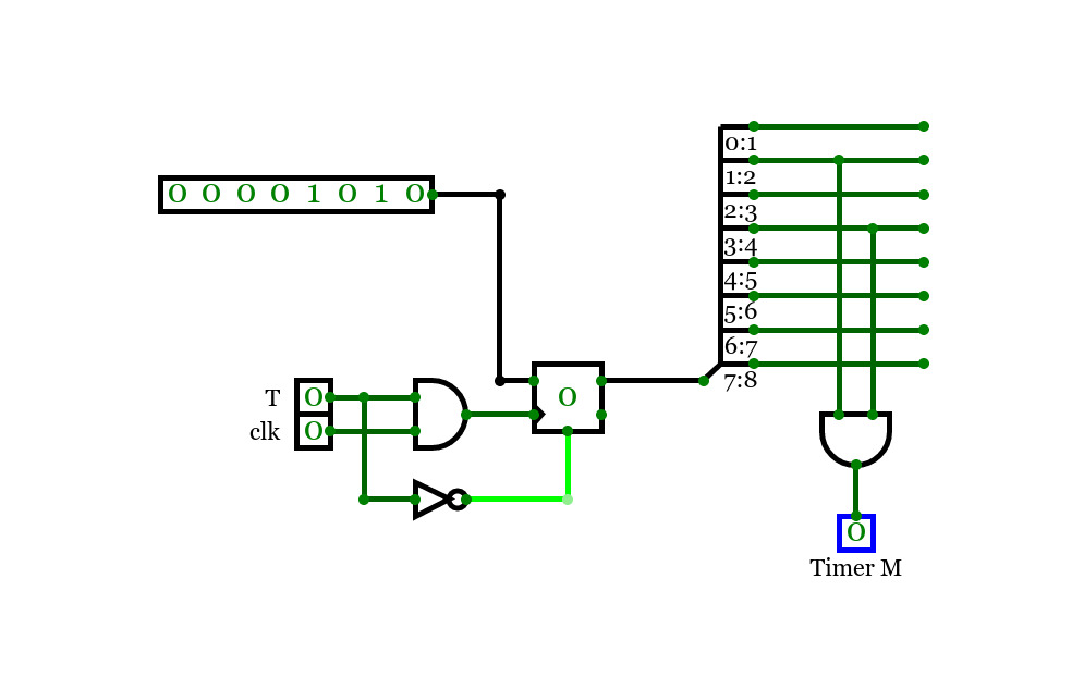
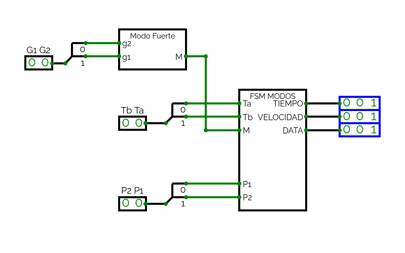
Module PracticePractice for creating and instantiating sub-circuits into a larger circuit, includes gate logic for some circuits like 2-to-1 mux and 3-to-8 decoder, as well as bit-to-bus combiner and FSM logic using T flip-flops.


