
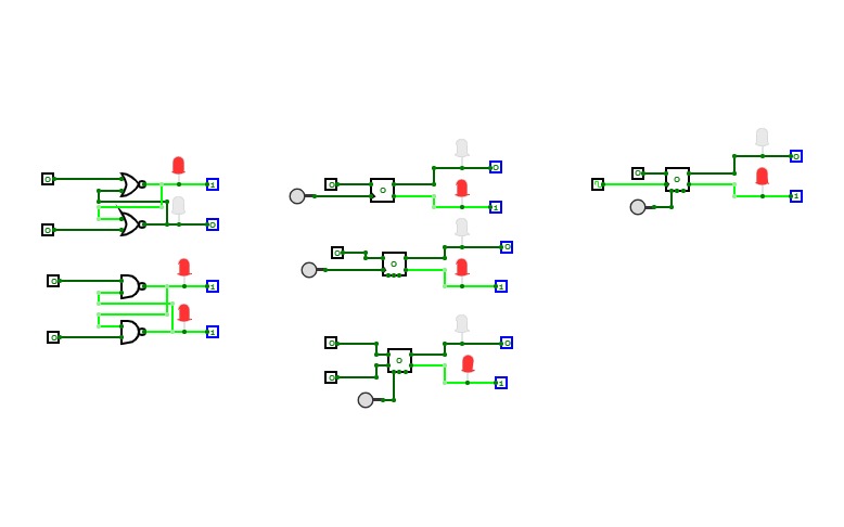
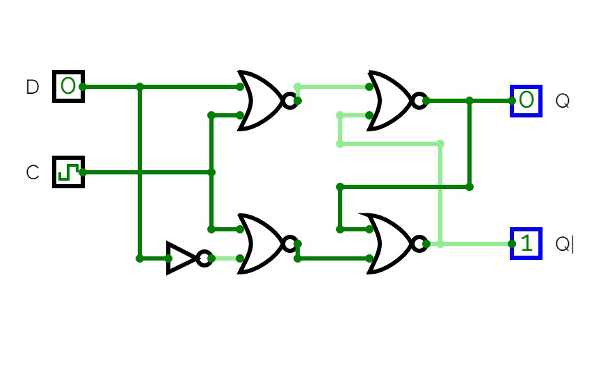
2 Bit asynchronous counter by using D-flipflop
2 Bit asynchronous counter by using D-flipflopThis is a 2-bit asynchronous counter.
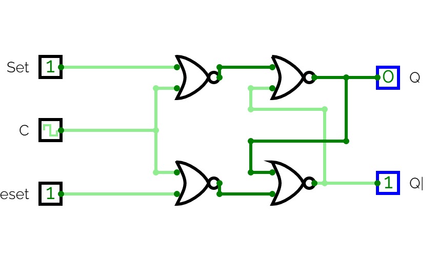
2 bit asynchronous counter using JK-Flipflop
2 bit asynchronous counter using JK-FlipflopThis is a 2-bit asynchronous counter.
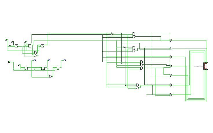
3-Bit synchronous up counter using JK-Flipflop
3-Bit synchronous up counter using JK-FlipflopThis is a 3-bit synchronous counter.
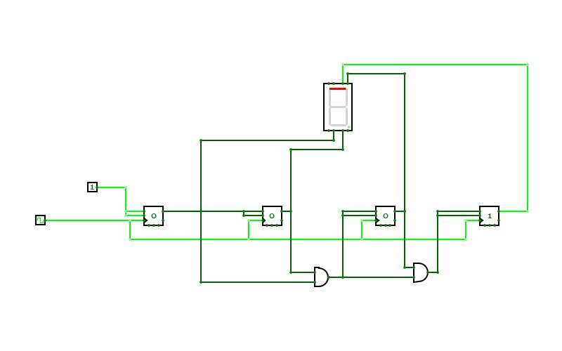
Seven
Seventhis is a seven segment counter
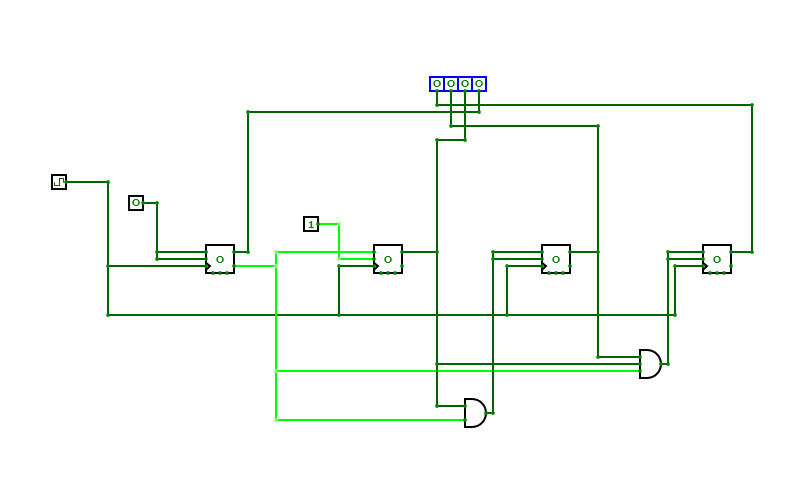
4-bit Even synchronous counter
4-bit Even synchronous counterThis is a 4-bit even synchronous counter.

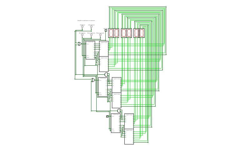
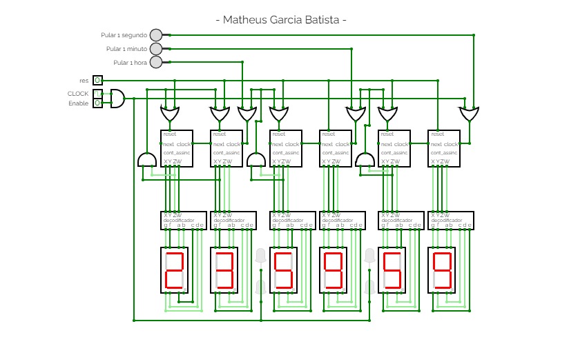
Clock/Reloj
Clock/RelojProgramable 24 hour clock created with T FlipFlops and 7 segment Displays. FlipFlops were used to create 0-59 and 0-23 counters.
Reloj de 24 horas programable que utiliza FlipFlops tipo T y Displays de 7 segmentos. Los FlipFlops se utilizaron para crear contadores de 0-59 y 0-23.
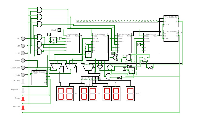
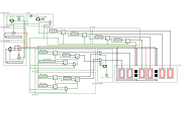

A Clock with a Display for Hours, Minutes and Seconds. Could be used too as a Counter with Stop and Go.
You can turn it On and Off, Reset the Clock and choose between 24h or 12h.
In the Simulator set the Clock Time to 500 ms to have the right timing for each second.
For Fun I added some blinking dots where you can change the Blinking mode.
Maybe I add a Fully RGB DOT Color Change in the Future :)
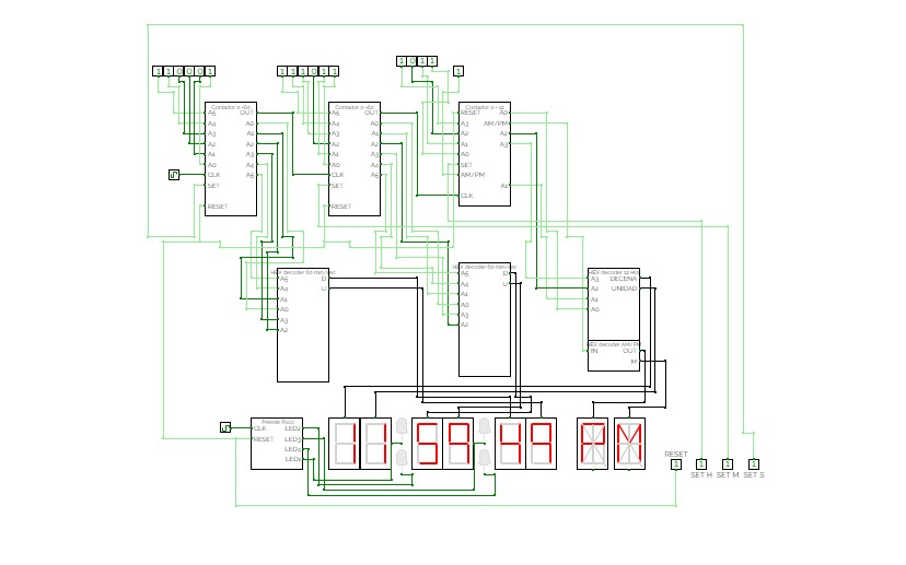
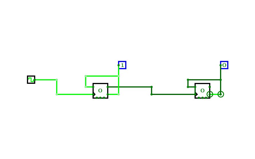
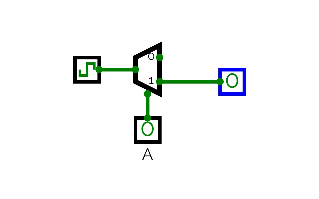
Clock
Clock
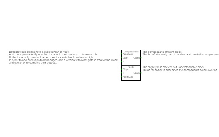

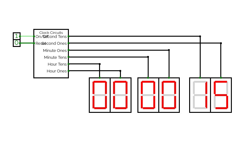
This is essentially the clock used by the Femto-4. Please use this instead of the old version made for Dustin Harris' 16-bit computer (which was directly ported from an old version of the Femto-4) for efficiency reasons.
What has changed?:
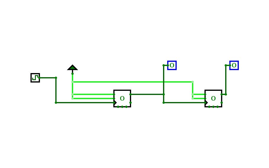
The old system used a pair of monostables running into each other to produce the pulse loop. This was bad, since each clock loop involved up to ten circuit updates per edge. The new system now only has a loop of three components, reducing the number of updates. The new loop is also naturally unstable, and no longer requires a pulse to start it, making it generally more flexible and stable should you wish to alter execution patterns.
Why should I use the new system?
The new system causes less updates. This has three primary benefits: a) You can overclock to higher speeds because less updates are involved, b) it causes less lag for the same overclocking speed, improving real time performance, and c) it is less fragile than the old clock and is more resilient to variations in how it is disabled.
What other alterations can be made to it?
The clock currently does not pulse on both edges of the default clock. Using monostable circuits can be used to do that, doubling the execution speed. Alternatively, two clocks, one which uses the negation of the clock, can be used like the Femto-4.
How does this work?
Please refer to: https://circuitverse.org/users/4699/projects/circuitverse-delay-introduction
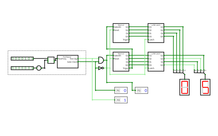
This circuit gives 2 clock signals. The higher one is to be used as the test signal for my frequency counter exercise, the lower one is to be used as the gate clock.
There are 2 inputs specifying how many test signal cycles per one gate clock in a BCD format, BCD0 is the ones place and the BCD1 is the tens place of that number.
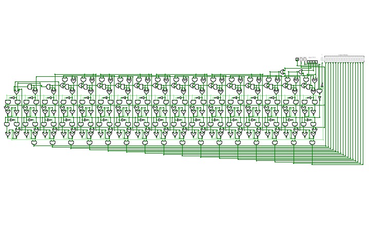

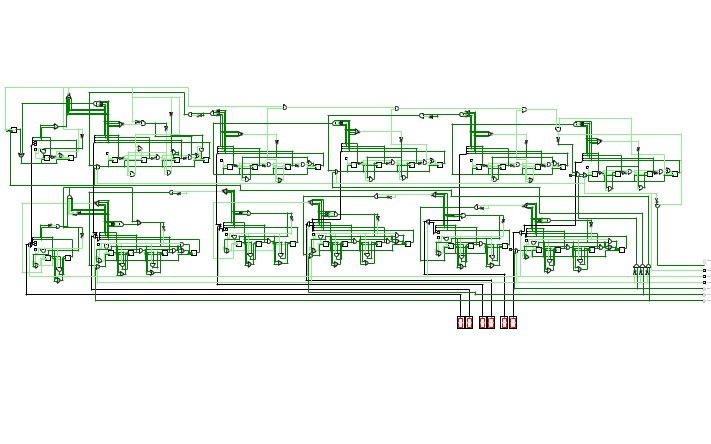
Serial BCD to binary
Serial BCD to binaryHello,
I have designed a special converter. Converts a BCD or Binary Coded Decimal number to 16-bit binary logical number. The special feature is the surprising sequential entry of numbers!
This conversion method uses a small number of logic gates and the operation is cyclical, so a clock is essential. Each BCD value entry is equal to one cycle. The converter consists of a register called the Accumulator, a 16-bit full adder and a wire connection that correctly multiplies the number by 10. A small control unit is also needed to monitor the system.
An Accumulator is a type of register, usually the first one used to store results.
The device works by adding a value from 0 to 9 to each BCD input, storing it in a register and then multiplying by 10. The cycle is repeated for each entry. so, for example, the number 123 in the BCD value 0001 0010 0011 is sent sequentially to the converter. The first number sent will be 0001. The adder will add 0001, then store the value in a register and multiply it by 10 in the binary form 1010, and the result will be 1010. We will then send a second BCD number 0010. This number will be added to the previous stored number 1010 and the resulting number will be 1100. This number is again stored in the register and multiplied by 10 according to the current time, the result will be 1111000. Then send a third BCD value 0011, which is added to the stored value 1111000 to get 1111011. Now read our final result 1111011!
This converter design is quick and easy. Unlike the others, it converts sequential BCD input values and contains a small number of logic gates. Dabble Double algorithms exist for this conversion, but they behave differently.
I have attached a diagram of how the device works below. I hope it will help you with your planning!
INSTRUCTIONS:
1. Reset the device before use!
(RST = Reset button)
2. Enter the BCD value!
(Inpu BCD)
3. After each entry, send the value!
(SND = Send)
4. Each entry is equal to one tick of the clock!
(CLK = Clock)
5. The error will be logged!
(E = Error)
6. Read the binary number!
(Output binary)
If you like my project, please give me a star (the button is on the bottom right), because it means a lot to me!
I hope you like the plan. I hope you enjoy the experience.