Searched Projects

Tags: 7

project.name
0 Stars     131 Views

circ

circ
7

project.name
0 Stars     109 Views

HARSHIT

HARSHIT
7

project.name
0 Stars     73 Views
User:

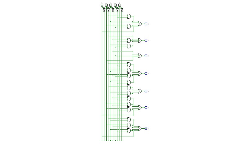
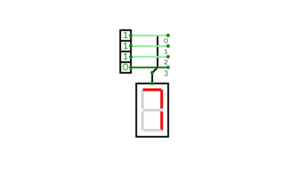
decodeur7bits

decodeur7bits
7

project.name
0 Stars     47 Views

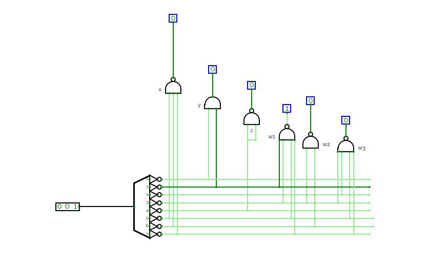
3*8 dec from 2*4 dec

3*8 dec from 2*4 dec

project.name
0 Stars     80 Views
User:

7-SegmentDisplayEC

7-SegmentDisplayEC

project.name
0 Stars     48 Views
User:

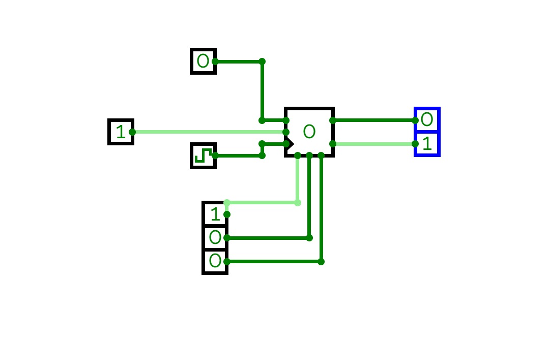
JK FLIPFLOP

JK FLIPFLOP
7

project.name
1 Stars     87 Views
User:

display

display

display de 7 segmentos


project.name
0 Stars     38 Views

7

7
7

project.name
0 Stars     137 Views

ARQ_LAB2

ARQ_LAB2

project.name
0 Stars     51 Views

LAB1_ACTIVIDAD2

LAB1_ACTIVIDAD2

project.name
0 Stars     40 Views

ACTIVITY 4

ACTIVITY 4
7

project.name
0 Stars     36 Views

7

7
7

magnitude


project.name
0 Stars     78 Views
User:

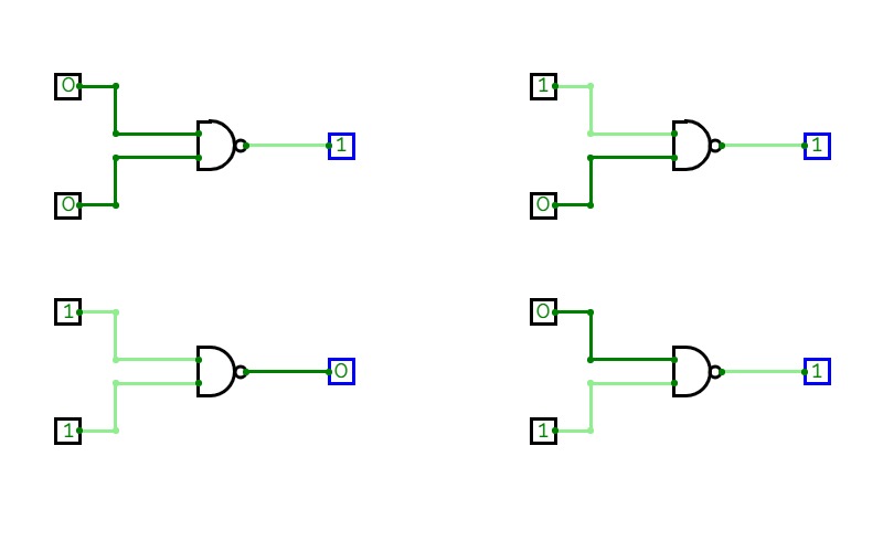
41_Vidhi_Logic Gates_(NAND)

41_Vidhi_Logic Gates_(NAND)
7

project.name
0 Stars     74 Views
User:

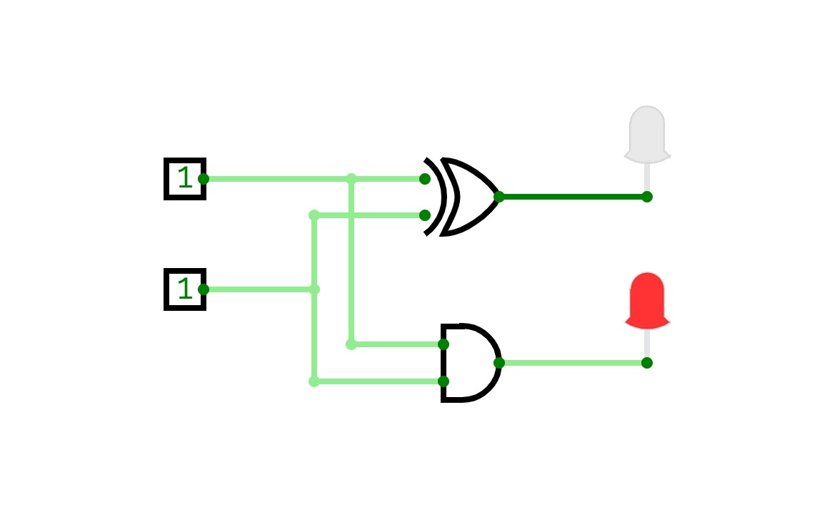
41_Vidhi_Half Adder

41_Vidhi_Half Adder
7

project.name
0 Stars     32 Views
User:

lab3

lab3
7

project.name
0 Stars     81 Views
User:

21UCS051_Exp9

21UCS051_Exp9
7

project.name
0 Stars     80 Views

20221_LAB2

20221_LAB2

project.name
0 Stars     68 Views

ARQ_LAB2

ARQ_LAB2

project.name
0 Stars     17 Views
User:

Basic logic gates

Basic logic gates
7

Experiment 1

Level 1


project.name
0 Stars     18 Views
User:

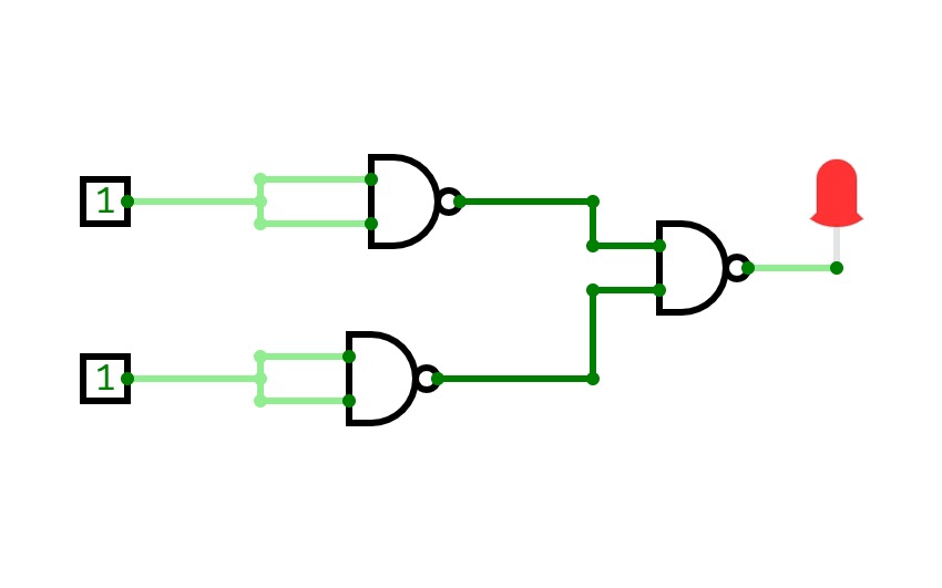
OR Gate using NAND Gate

OR Gate using NAND Gate
7

Transformation of NAND Gate into OR gate


project.name
0 Stars     36 Views

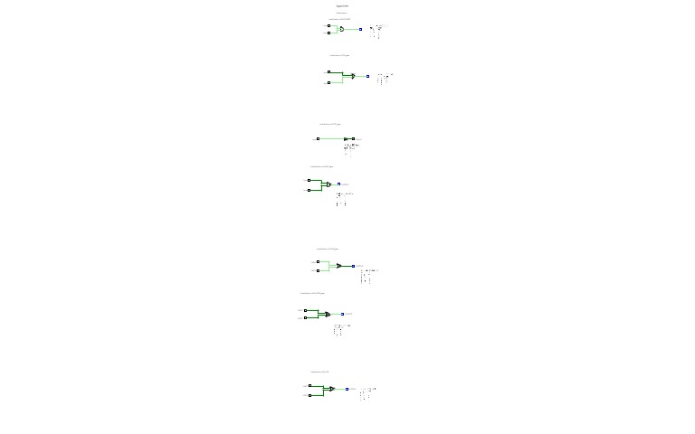
GATE VERIFICATION

GATE VERIFICATION
1 2 3 4 5 6 7

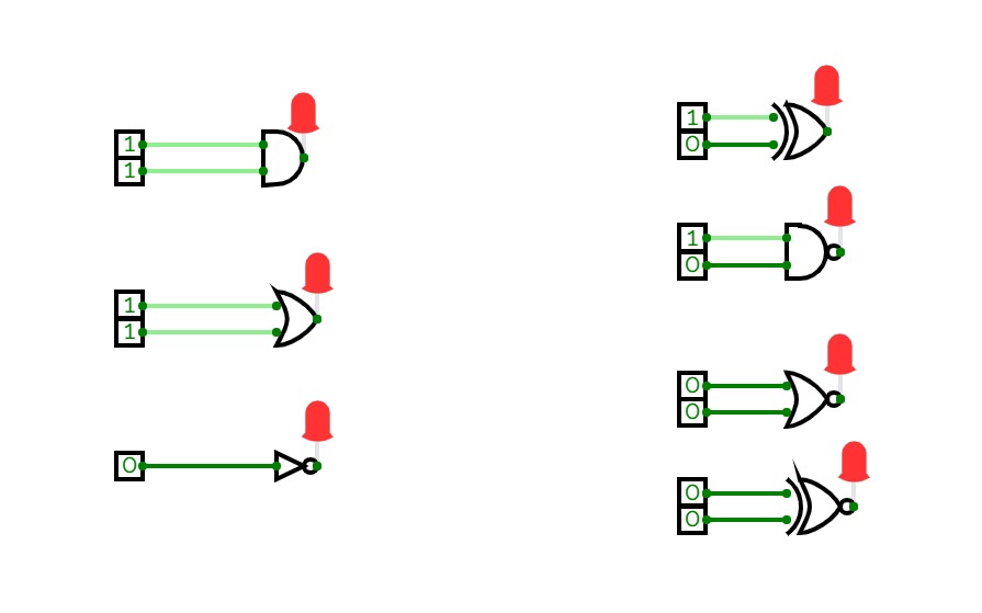
his is a NOT-AND gate which is equal to an AND gate followed by a NOT gate. The outputs of all NAND gates are high if any of the inputs are low. The symbol is an AND gate with a small circle on the output. The small circle represents inversion.

This is a NOT-OR gate which is equal to an OR gate followed by a NOT gate. The outputs of all NOR gates are low if any of the inputs are high. The symbol is an OR gate with a small circle on the output. The small circle represents inversion.

The NOT gate is an electronic circuit that produces an inverted version of the input at its output. It is also known as an inverter. If the input variable is A, the inverted output is known as NOT A. 

The 'Exclusive-OR' gate is a circuit which will give a high output if either, but not both of its two inputs are high. An encircled plus sign (⊕) is used to show the Ex-OR operation.

The 'Exclusive-NOR' gate circuit does the opposite to the EX-OR gate. It will give a low output if either, but not both of its two inputs are high. The symbol is an EX-OR gate with a small circle on the output. The small circle represent


project.name
0 Stars     42 Views

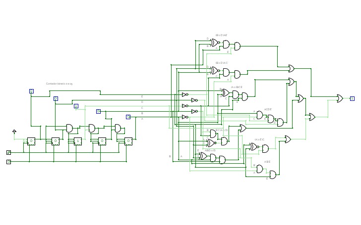
Mapas K (5 bits)

Mapas K (5 bits)

project.name
0 Stars     10 Views

Untitled

Untitled
7

project.name
0 Stars     15 Views

Untitled

Untitled
1 4 7

project.name
0 Stars     51 Views
User:

JOJIE ,CABRILLOS

JOJIE ,CABRILLOS
S E n i o r 0 7

project.name
0 Stars     15 Views
User:

exp 7

exp 7
7

project.name
0 Stars     6 Views
User:

display 7 segmentos

display 7 segmentos

project.name
0 Stars     12 Views

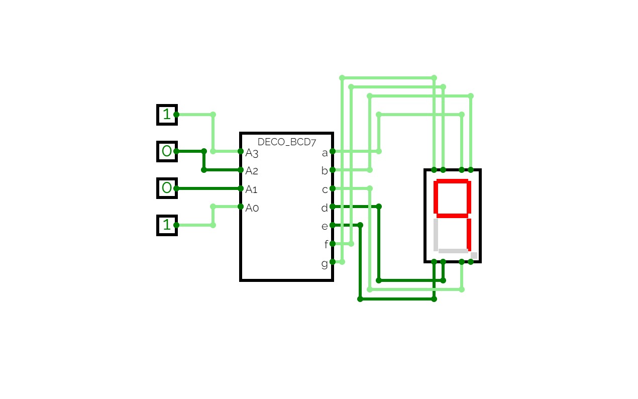
DecoBCD7Seg

DecoBCD7Seg

Decodificar BDC 7 Segmentos


project.name
0 Stars     3 Views

verification of logic gates 7

verification of logic gates 7
7

project.name
0 Stars     3 Views

Distributive Law

Distributive Law
7