Searched Projects

Tags: 5

project.name
0 Stars     109 Views

multiplexador 4x1

multiplexador 4x1
5

project.name
0 Stars     100 Views

HARSHIT

HARSHIT
5

project.name
0 Stars     107 Views

Hamming

Hamming
5

project.name
0 Stars     69 Views

Alu

Alu
5

project.name
0 Stars     58 Views
User:

exp 5

exp 5
5

project.name
0 Stars     69 Views

Experiment 1

Experiment 1
1 2a 2b 3 4a 4b 5 6 7a 7b 8 9

NIKHIL GUPTA 

1960627


project.name
0 Stars     31 Views

EXPERIMENT 4

EXPERIMENT 4
5

project.name
1 Stars     94 Views

experement 2 2,3,4,5, question 2061008

experement 2 2,3,4,5, question 2061008

 question no ; 2,3,4,5


project.name
0 Stars     34 Views
User:

T FLIPFLOP

T FLIPFLOP
5

project.name
0 Stars     31 Views

Untitled

Untitled
5

project.name
0 Stars     47 Views

2*4 Decoder

2*4 Decoder

project.name
0 Stars     73 Views

2Lista

2Lista
Ex 2 4 5 6

project.name
0 Stars     72 Views

Activity 3

Activity 3
1 2 3 4 5

project.name
0 Stars     32 Views

ACTIVITY 4

ACTIVITY 4
5

project.name
0 Stars     17 Views

NAMRATA

NAMRATA
EX 5

project.name
0 Stars     27 Views
User:

41_Vidhi_Logic Gates_(NOT)

41_Vidhi_Logic Gates_(NOT)
5

project.name
0 Stars     64 Views
User:

21UCS051_Exp9

21UCS051_Exp9
5

project.name
0 Stars     12 Views

5

5
5

project.name
0 Stars     5 Views

verification of boolean law

verification of boolean law
5

berification of boolean law


project.name
0 Stars     7 Views

mod 5 synchronous updown counter

mod 5 synchronous updown counter
mod 5

project.name
0 Stars     11 Views
User:

exp 2

exp 2
5 6

adder,subtraction


project.name
0 Stars     7 Views
User:

OR gate using NOR gate

OR gate using NOR gate
5

transformation  of NOR Gate into OR Gate


project.name
0 Stars     7 Views
User:

AND Gate using NOR Gate

AND Gate using NOR Gate
5

Transformation of NOR Gate AND Gate


project.name
0 Stars     12 Views
User:

EXP 4...encoder and decoder logic circuits

EXP 4...encoder and decoder logic circuits
9 5

encoder and decoder


project.name
0 Stars     13 Views
User:

2 to 4 decoder

2 to 4 decoder
8 5

decoder


project.name
0 Stars     9 Views
User:

exp 5: design of logic diagram using NAND gates

exp 5: design of logic diagram using NAND gates
5 2

exp 5-using NAND Gates


project.name
0 Stars     5 Views
User:

EXP 6: JK Flip-flop implementation using nand gate

EXP 6: JK Flip-flop implementation using nand gate
5

LEVEL 2


project.name
0 Stars     18 Views

Assignment4

Assignment4
Q.1 2 3 4 5

project.name
0 Stars     24 Views

GATE VERIFICATION

GATE VERIFICATION
1 2 3 4 5 6 7

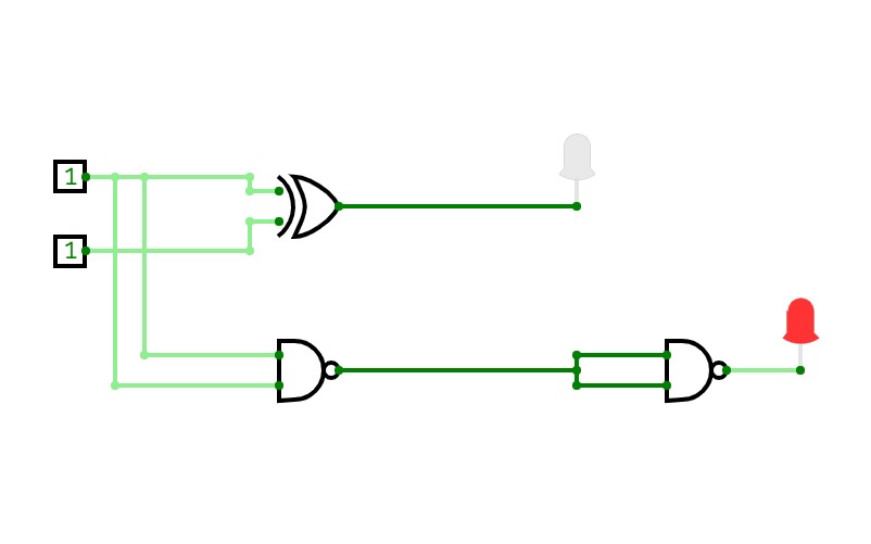
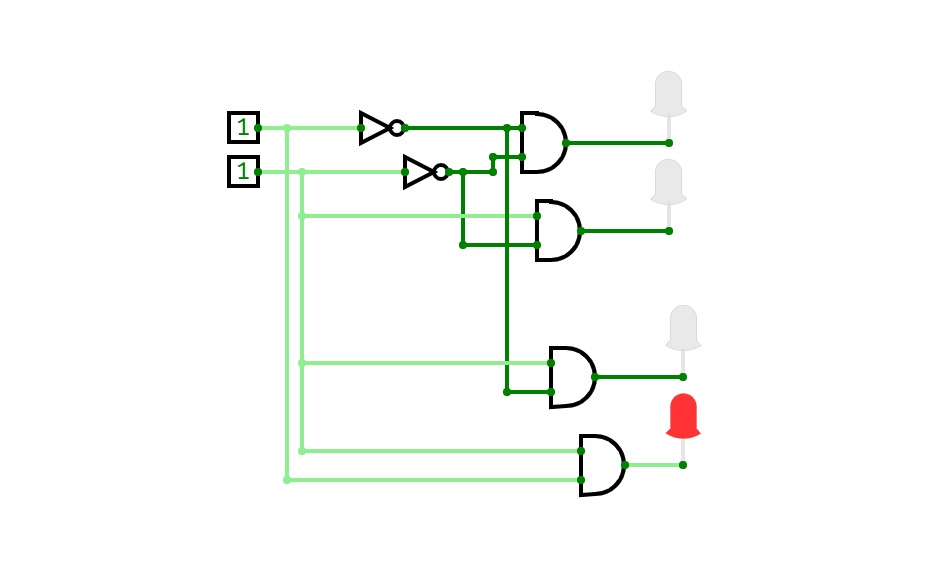
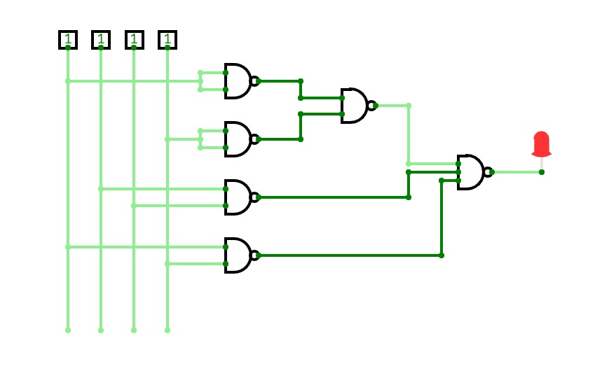
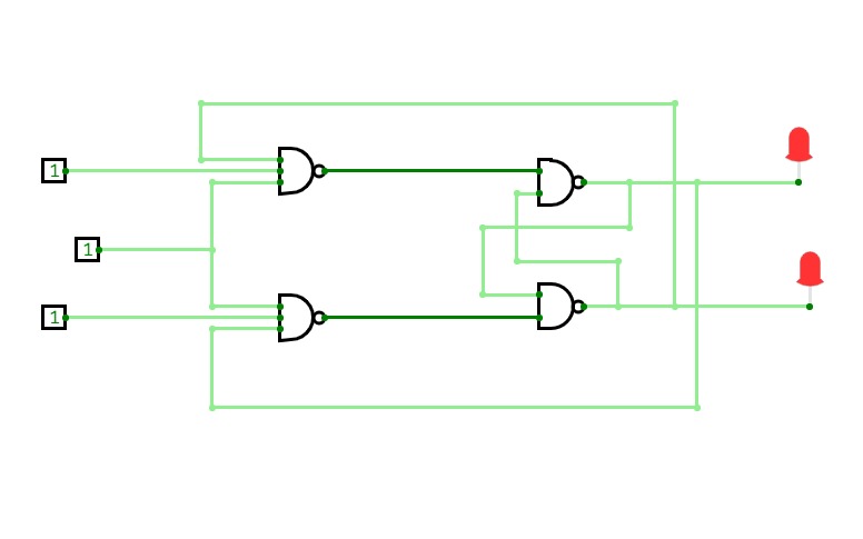
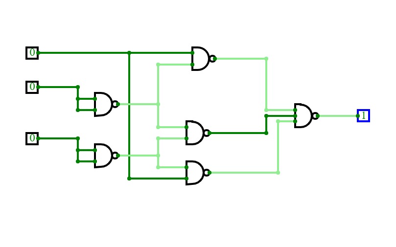
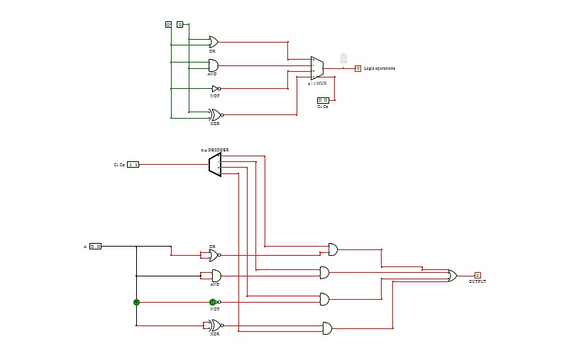
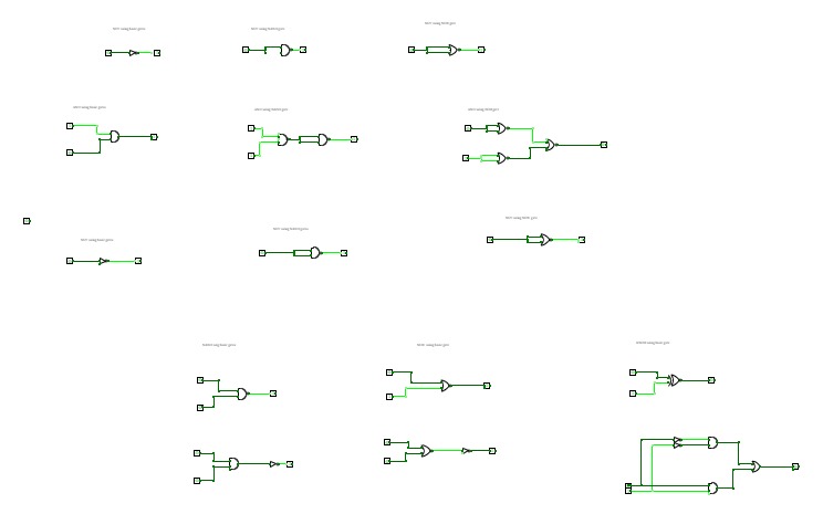
his is a NOT-AND gate which is equal to an AND gate followed by a NOT gate. The outputs of all NAND gates are high if any of the inputs are low. The symbol is an AND gate with a small circle on the output. The small circle represents inversion.

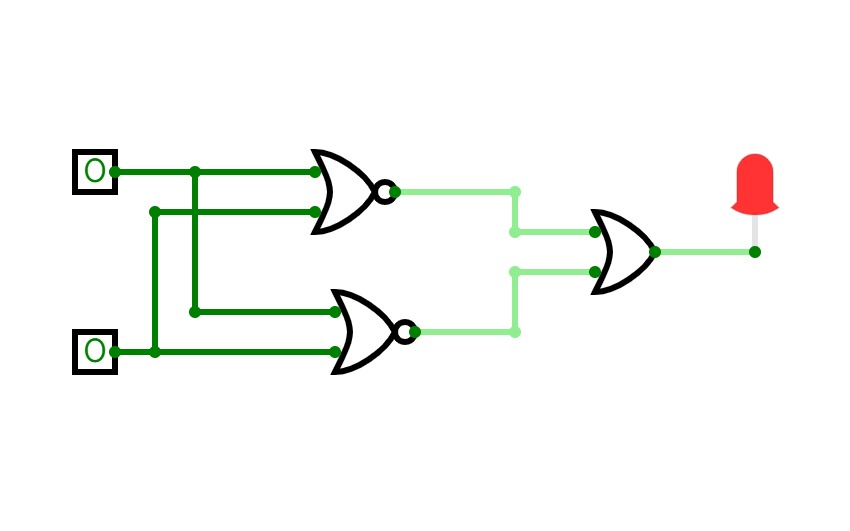
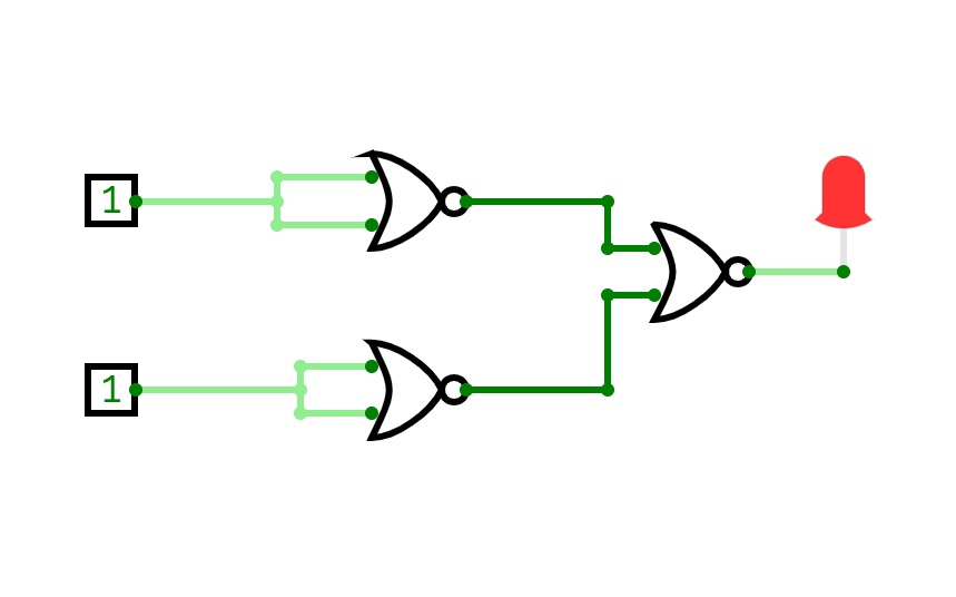
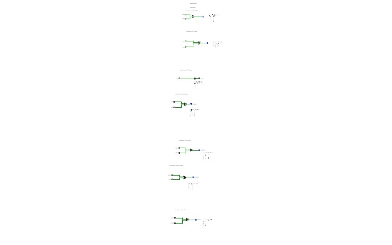
This is a NOT-OR gate which is equal to an OR gate followed by a NOT gate. The outputs of all NOR gates are low if any of the inputs are high. The symbol is an OR gate with a small circle on the output. The small circle represents inversion.

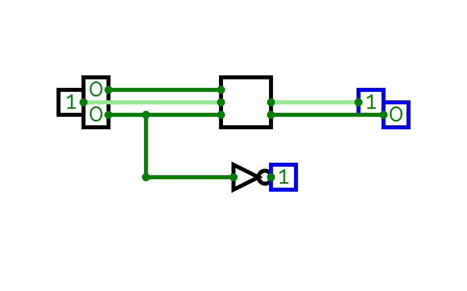
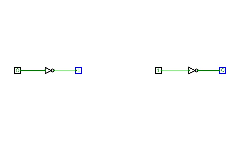
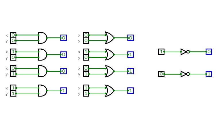
The NOT gate is an electronic circuit that produces an inverted version of the input at its output. It is also known as an inverter. If the input variable is A, the inverted output is known as NOT A. 

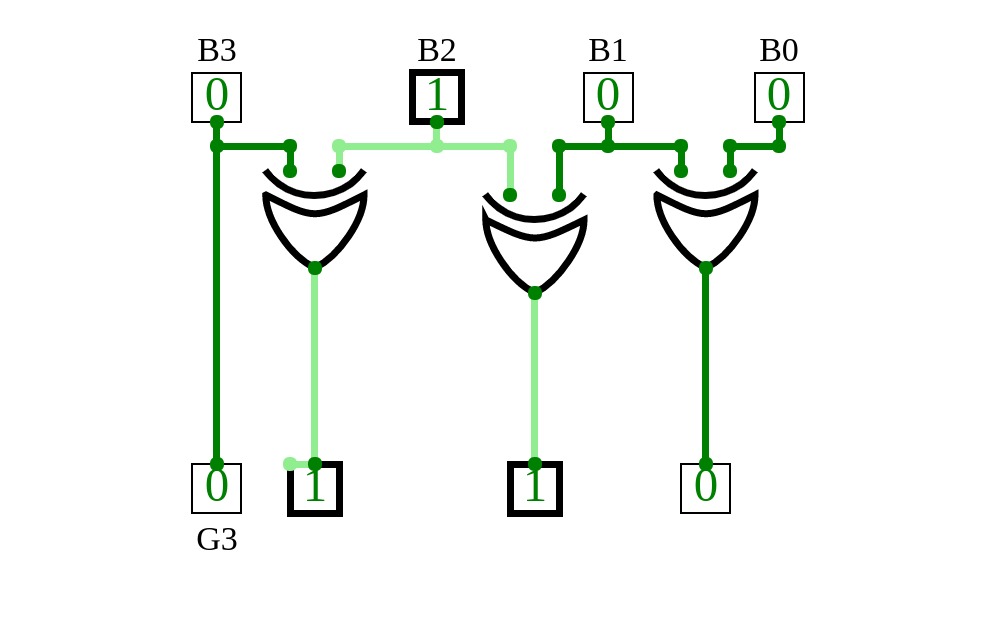
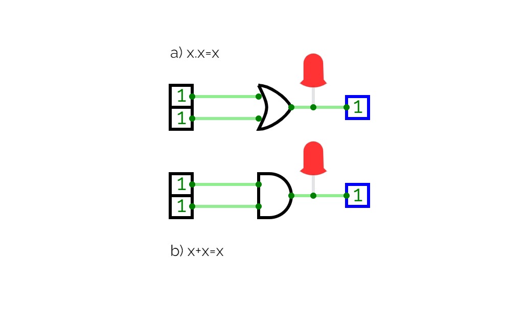
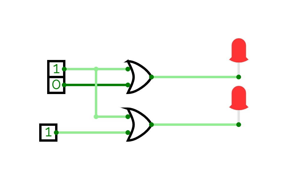
The 'Exclusive-OR' gate is a circuit which will give a high output if either, but not both of its two inputs are high. An encircled plus sign (⊕) is used to show the Ex-OR operation.

The 'Exclusive-NOR' gate circuit does the opposite to the EX-OR gate. It will give a low output if either, but not both of its two inputs are high. The symbol is an EX-OR gate with a small circle on the output. The small circle represent


project.name
0 Stars     17 Views
User:

project.name
0 Stars     29 Views

Mapas K (5 bits)

Mapas K (5 bits)

project.name
0 Stars     11 Views
User:

NAND Circuit diagram

NAND Circuit diagram

project.name
0 Stars     2 Views
User:

exp-5 continue

exp-5 continue
5