
JK Flip Flop
JK Flip Flop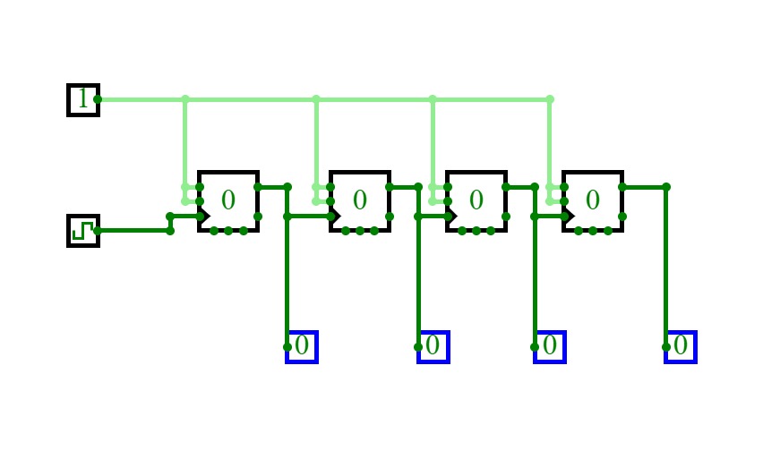
Async Counter
Async Counter4 Bit Asynchronous Counter using JK Flip-FLop
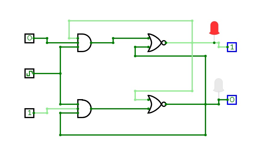
Sequential Circuit
Sequential Circuit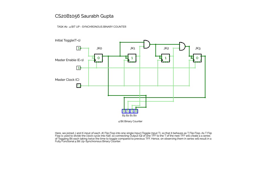

4 Bit Up-Synchronous Binary Counter
4 Bit Up-Synchronous Binary Counter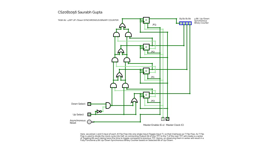
4 Bit Up/Down Synchronous Binary Counter
4 Bit Up/Down Synchronous Binary Counter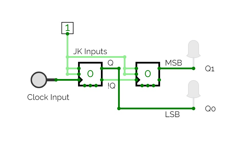
Asynchrnous Up Counter
Asynchrnous Up CounterTwo bit Asynchronous up counter that counts from 00 to 11 and back.
Experiment 07
Experiment 07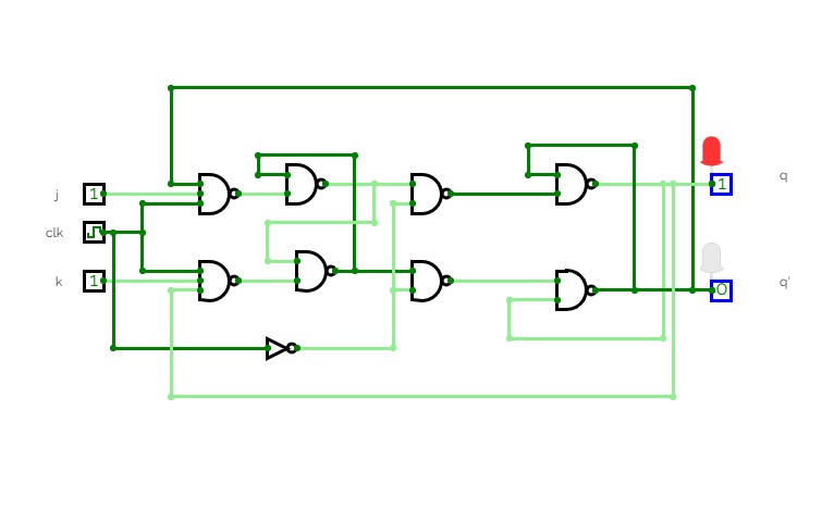
Master Slave Circuit(Experiment 07- Level 02)
Master Slave Circuit(Experiment 07- Level 02)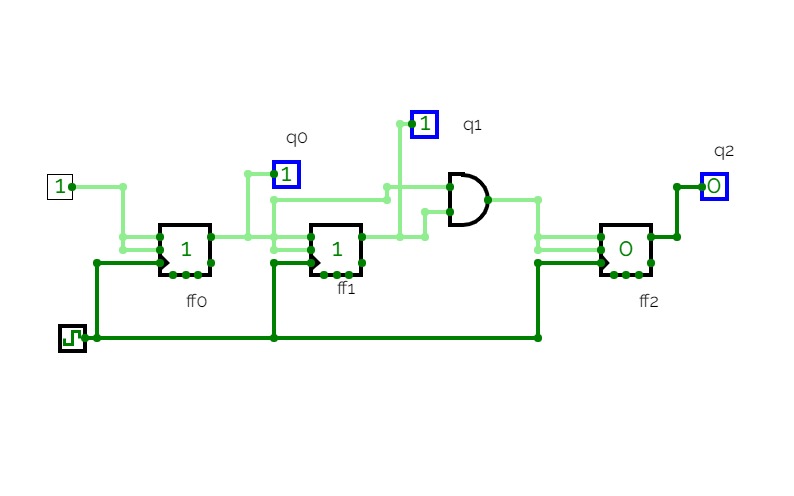
3-bit synchronous counter using JKFF
3-bit synchronous counter using JKFF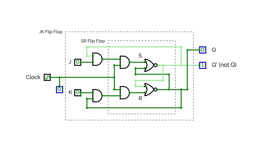
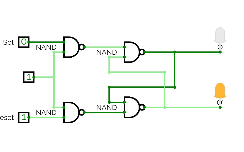
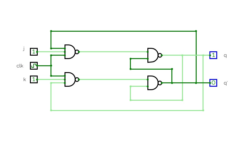
JK Flip Flop
JK Flip FlopJK Flip Flop using SR Flip Flop (implemented with NOR gates)
Reference: The Essentials of Computer Organization and Architecture, 5th Edition. Linda Null and Julia Lobur. Chapter 3, pages 178 - 179.
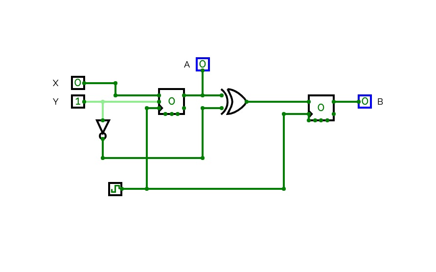
Exercise 62 Sequential Circuit
Exercise 62 Sequential CircuitSequential circuit used in Exercise 62 from Null & Lobur, Computer Organization and Architecture, 5th Ed.
JK flip flop test
JK flip flop test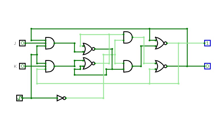
JK Flip Flop
JK Flip FlopJK Flip Flop

JK Flip Flop
JK Flip FlopA collection of different JK Flip Flop Circuits. If you're finding this from the CDA Computer Org review the Basic JK Flip Flop is the circuit we learned about in class.
(See this Stack Exchange post for more info https://electronics.stackexchange.com/questions/491352/jk-latch-possible-ben-eater-error/491439#491439)


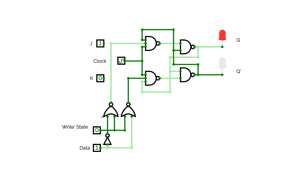
JK flipflop 60second timer with start, stop, reset and display
JK flipflop 60second timer with start, stop, reset and displayThis is from a small project that was done for school, the purpose for saving this online is so that the teacher can interact with it and grade it for himself.

Synchrous counter for sequence 7,2,3,0,4,7,2..
Synchrous counter for sequence 7,2,3,0,4,7,2..Synchrous counter for sequence 7,2,3,0,4,7,2..
Synchrous counter for sequence 7,2,3,0,4,7,2..Thesequential circuit employed in this project is a synchronous counter using JK flip flop, which counts through the series 7,2,3,0,4,2..
Firstly the state diagram of counter was employed: 000->100->111->010->011->000.
Since sequence involves 3 bit number, number of flip flops employed= 3
Based on state diagram, table representing present state and next state was developed [(Q2,Q1,Q0) and (Q2+,Q1+,Q0+)]. -- table(1)
Characteristic Table for JK Flip Flop:

From Characteristic table, expression for input J and K were developed using K map.(3 different expression for J and K)
J2=Q1' K2=Q1
J1 = Q2 K1=Q2' Q0
J0=Q1+Q2 K0=Q0
To implement the values of J and K necessary gates were employed, and common clock was given to all 3 flip flops


