

ADE-5 Multiplexer simulation
ADE-5 Multiplexer simulation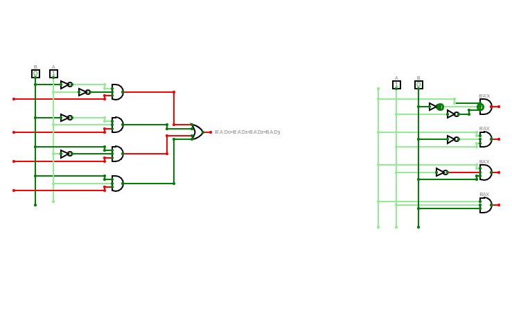
EXP 2 (A)
EXP 2 (A)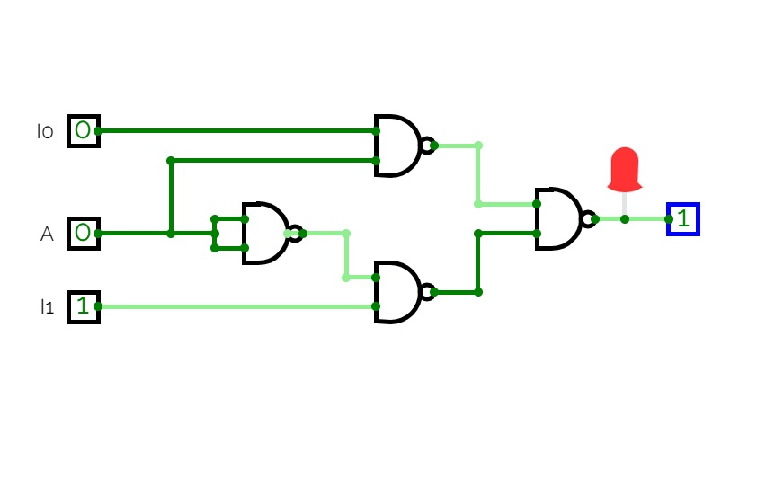
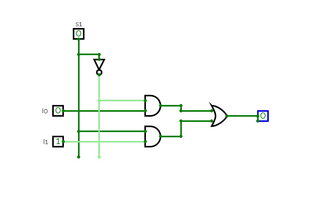
2*1 MUX
2*1 MUX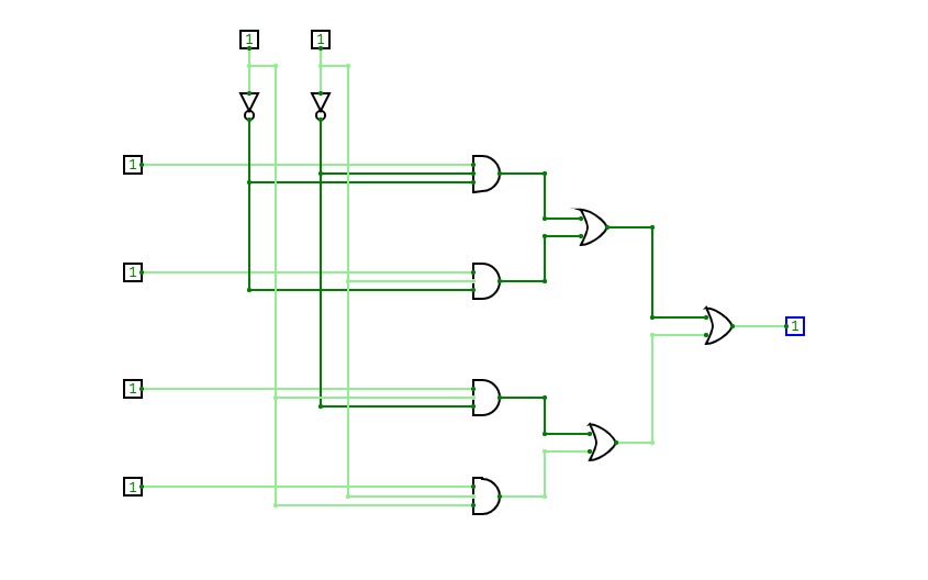
Untitled
Untitled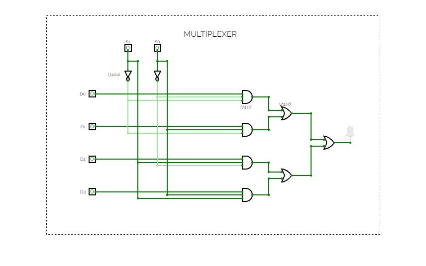
MUHAMMED ANAS P
MUHAMMED ANAS PMUHAMMED ANAS P
ROLL.NO:28
REG.NO:20919028
Untitled
Untitled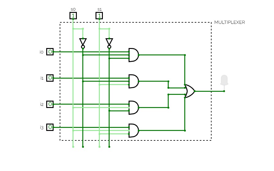
MULTIPLEXER
MULTIPLEXER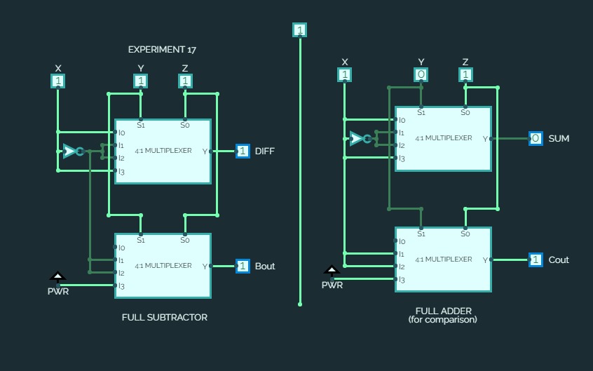

EXPERIMENT 17
EXPERIMENT 17Implementation of a Full Subtractor using MUX IC 4539B
MULTIPLEXER..FORFAISALWEDSPAYALGOD
MULTIPLEXER..FORFAISALWEDSPAYALGODMultiplexer implementation for the question
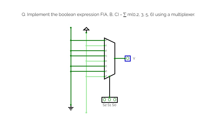
Q.1 Implement the boolean expression F(A, B, C) = ∑ m(0,2, 3, 5, 6) using a multiplexer.
4mux
4muxNOTHING
4x1 Multiplexer
4x1 MultiplexerMultiplexer is a combinational circuit that has maximum of 2n data inputs, ‘n’ selection lines and single output line. One of these data inputs will be connected to the output based on the values of selection lines.
Since there are ‘n’ selection lines, there will be 2n possible combinations of zeros and ones. So, each combination will select only one data input. Multiplexer is also called as Mux.
4x1 Multiplexer
4x1 Multiplexer has four data inputs I3, I2, I1 & I0, two selection lines s1 & s0 and one output Y. The block diagram of 4x1 Multiplexer is shown in the following figure.
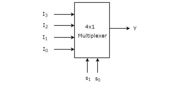
One of these 4 inputs will be connected to the output based on the combination of inputs present at these two selection lines. Truth table of 4x1 Multiplexer is shown below.
TRUTH TABLE
Selection LinesOutputS1S0Y00I001I110I211I3
From Truth table, we can directly write the Boolean function for output, Y as
Y=S1′S0′I0+S1′S0I1+S1S0′I2+S1S0I3Y=S1′S0′I0+S1′S0I1+S1S0′I2+S1S0I3
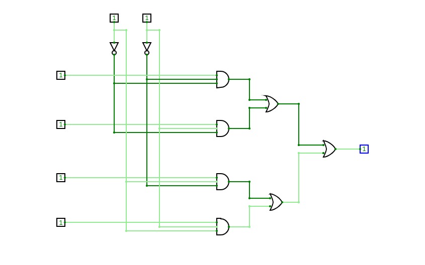
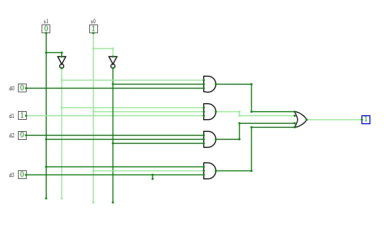
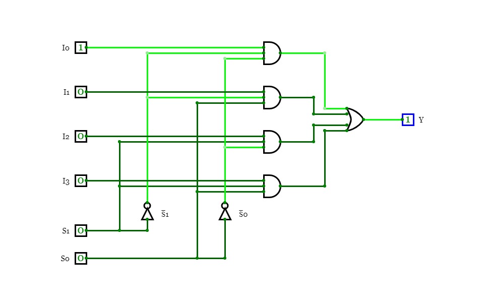
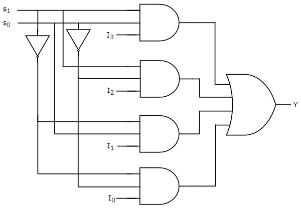
We can implement this Boolean function using Inverters, AND gates & OR gate. The circuit diagram of 4x1 multiplexer is shown in the following figure.
CIRCUIT DAIGRAM
8x1 Multiplexer
8x1 Multiplexer8x1 Multiplexer
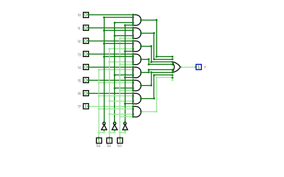
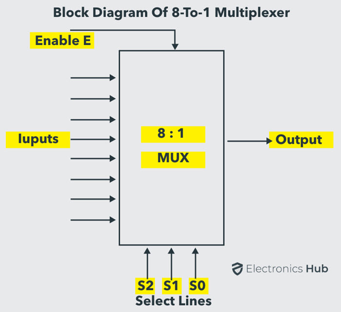
In the 8 to 1 multiplexer, there are total eight inputs, i.e., A0, A1, A2, A3, A4, A5, A6, and A7, 3 selection lines, i.e., S0, S1and S2 and single output, i.e., Y. On the basis of the combination of inputs that are present at the selection lines S0, S1, and S2, one of these 8 inputs are connected to the output.
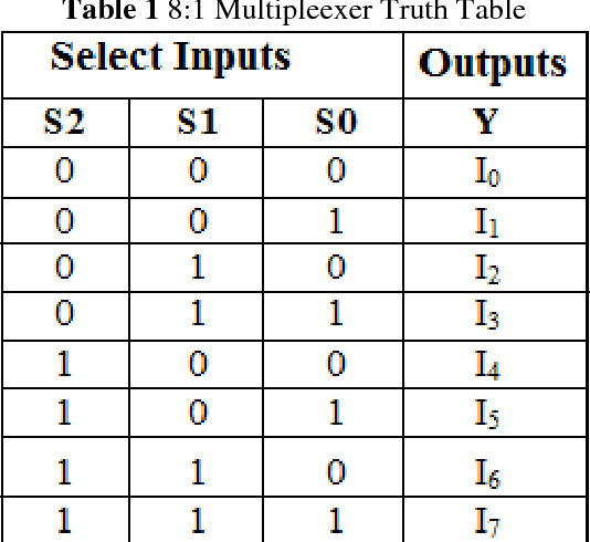
Let the 8x1 Multiplexer has eight data inputs I7 to I0, three selection lines s2, s1 & s0 and one output Y. The Truth table of 8x1 Multiplexer is shown below.
BLOCK DIAGRAM
2X1 multiplexer
2X1 multiplexer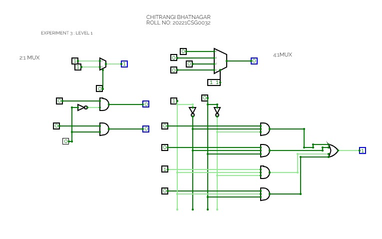
EXPERIMENT 3 LEVEL1
EXPERIMENT 3 LEVEL1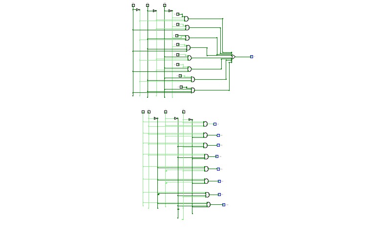
SUMIT KUMAR SINGH
SUMIT KUMAR SINGH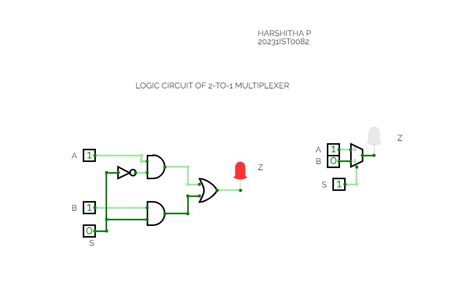
Untitled
Untitled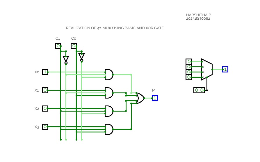
EXP 3 4:1 MUX
EXP 3 4:1 MUX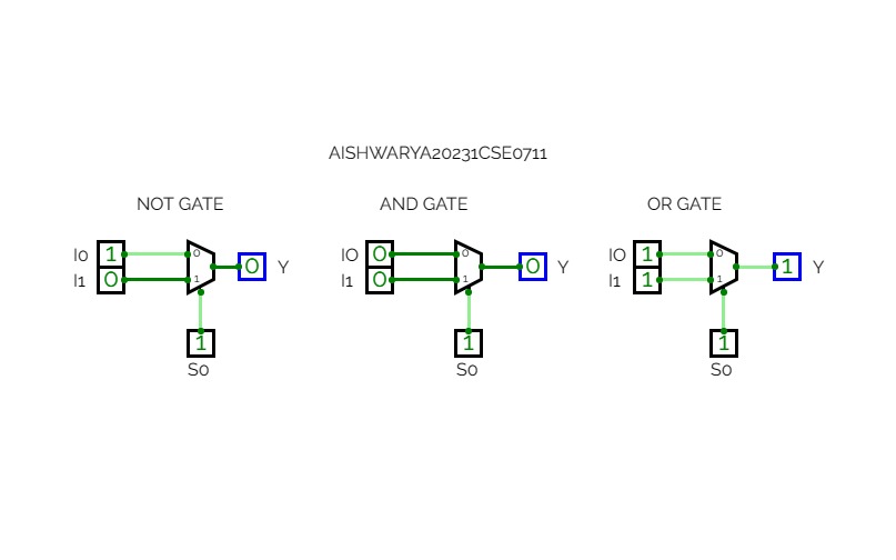
EXPERIMENT - 9
EXPERIMENT - 9AISH

EXPERIMENT 8
EXPERIMENT 8
EXPERIMENT - 8
EXPERIMENT - 8AISH

8:3 MULTIPLEXER && 3:8 DECODER
8:3 MULTIPLEXER && 3:8 DECODER
EXPERIENT: 06
EXPERIENT: 06
8x1 MULTIPLEXER
8x1 MULTIPLEXERAn 8x1 multiplexer is a digital switch that selects one of eight input signals and forwards it to a single output based on a 3-bit selection input.


