Tailson 1
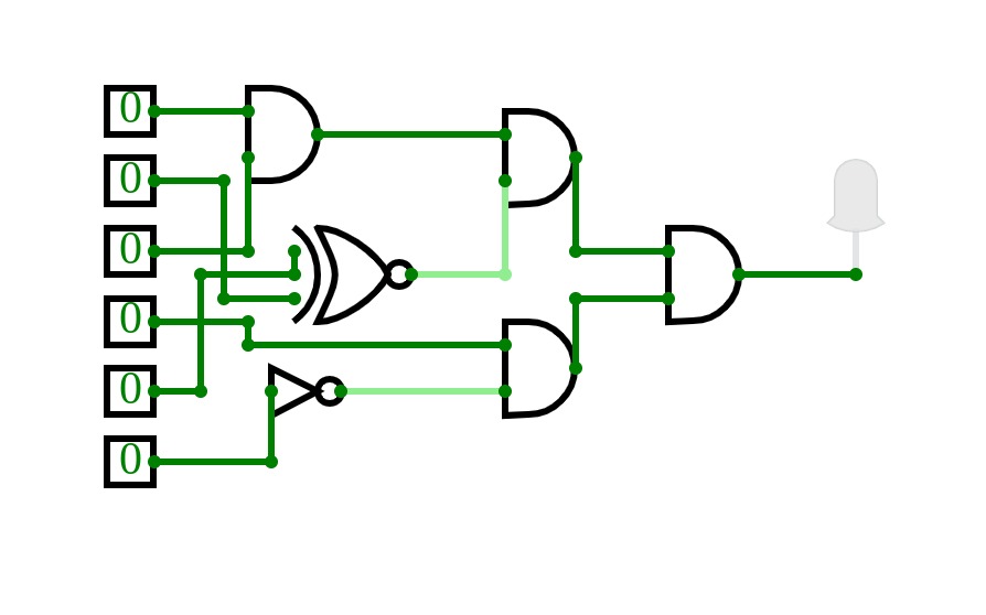
Tailson 1Detector de circuito de erro em código BCD com o acionamento de uma lâmpada( Sinal Alto).
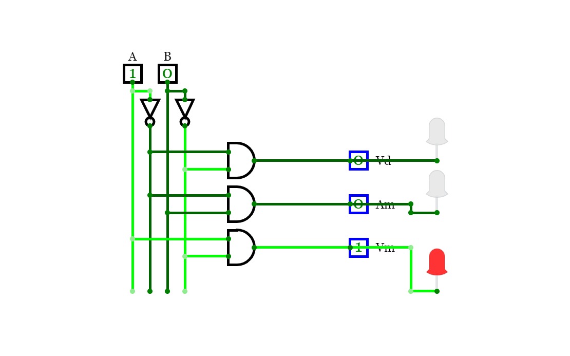
SEMÁFORO
SEMÁFOROLock #1
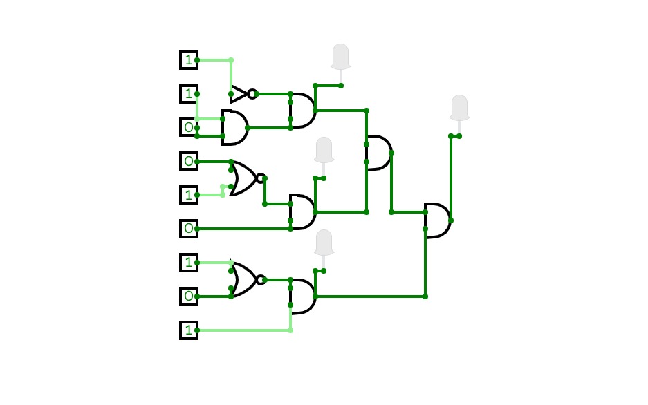
Lock #1Just wanted to make something cool for a FIRST PROJECT and decided on a lock.
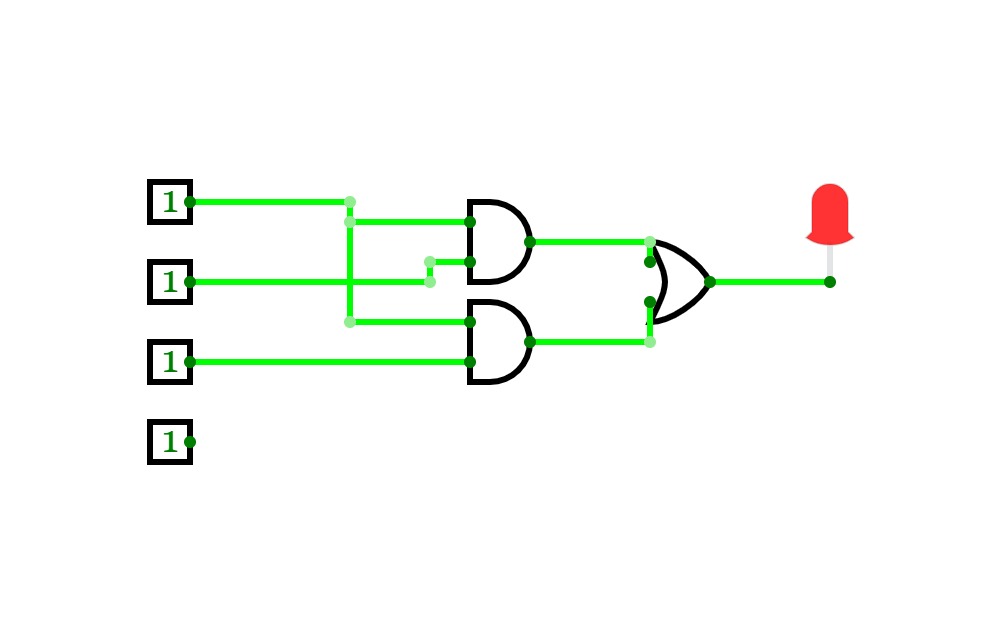
Pass code puzzle
Pass code puzzleThe goal is to get the light on by finding the right code using the gates.
JCU 501 (Programmable CPU)
JCU 501 (Programmable CPU)New and improved JCU 501! The new JCU 501 contains two accumulators (one for each input), as well as capacity to handle it's own input stream.
You can either use the ROM or the RAM to program it
Functions:
0 - A OR B / 0000
1 - A AND B / 0001
2 - A XOR B / 0010
3 - A + B / 0011
4 - A NOR B / 0100
5 - A NAND B / 0101
6 - A XNOR B / 0110
7 - !(A + B) / 0111
8 - A = B / 1000
9 - A > B / 1001
a - A < B / 1010
b - 0 / 1011
c - A != B / 1100
d - A <= B / 1101
e - A >= Bf - 1 / 1110
Addresses:
0 - 0000
1 - 0001
2 - 0010
3 - 0011
4 - 0100
5 - 0101
6 - 0110
7 - 0111
8 - 1000
9 - 1001
a - 1010
b - 1011
c - 1100
d - 1101
e - 1110
f - 1111
Tags (ignore):
This is My 4 Bit computer with 6 instructions just like the SAP Computer. :)
Instructions:
00 NOP
1x LDA
2x ADD
3x SUB
ee OUT
4x OUT_S
ff END
Warning:
This computer cannot calculate more than 2 numbers
This Example Program shows 5+7 and 4-5.
To Program, Set the Reset Bit to 1 and Program the ROM.
To Run the Program, Set the Reset Bit to 0.
The Numbers in the output are in Two's Complement so if the number is more than 7
than the number will be negative because 7 is the biggest number in 4 bits.
16-Bit CPU (unfinished)
16-Bit CPU (unfinished)Example code (in Binary):
0000000001101000
0000000001101010
0000000000000001
Example code (in HEX):
0x68
0x6a
0x01
Example code (in asm):
SAVE 1101 R1
OUT R1
RST R1
Example code (explanation):
Saves "1101" in register 1
Outputs what's in register 1
Resets register 1
I'll add more instructions, functions and features in the future


