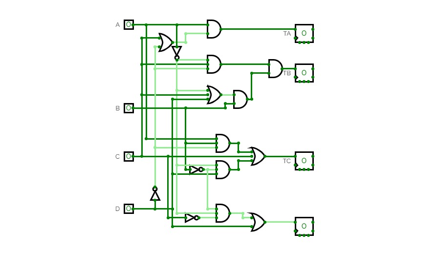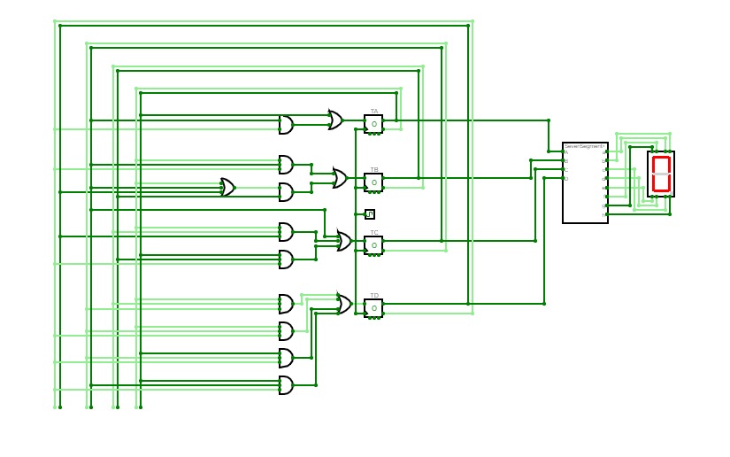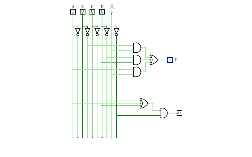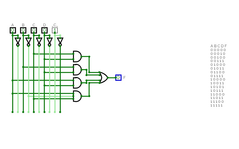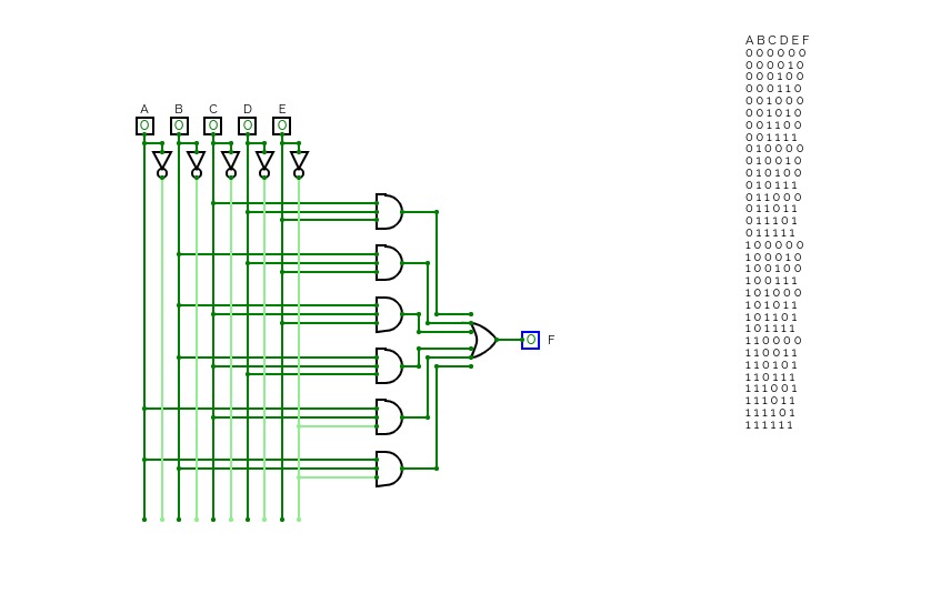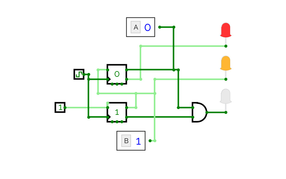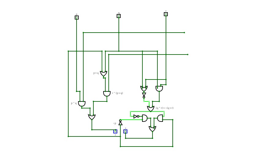
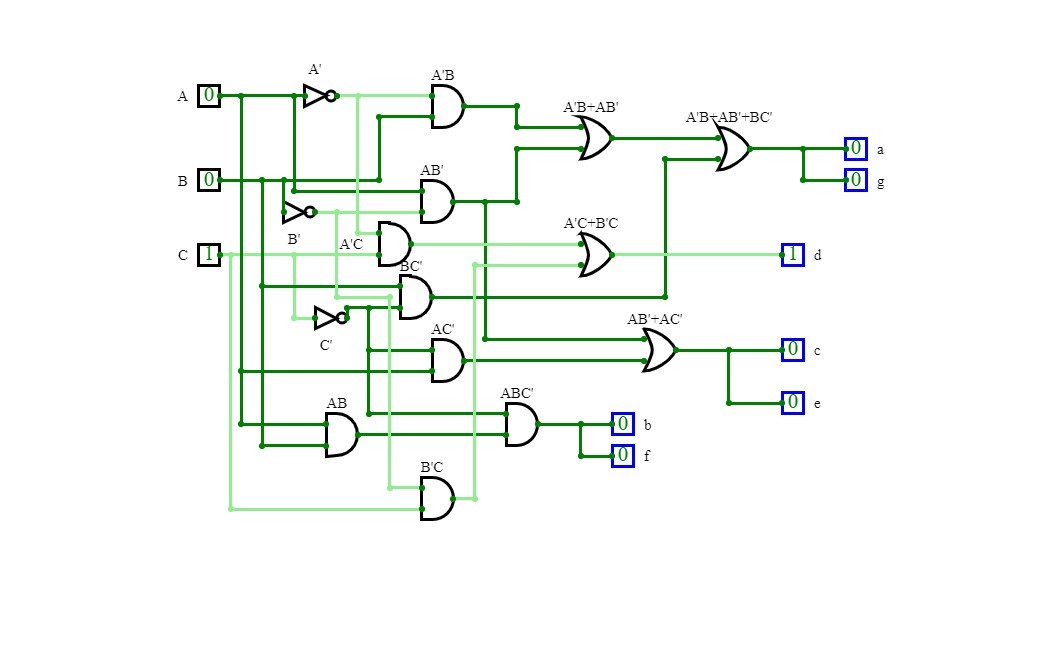
Lab: Designing a dice with LEDs
Lab: Designing a dice with LEDsA system that displays the output of roller dice 1 to 6 on different inputs. The outputs at all 0's and 1's is all zero i.e., the case of I DON't CARE.
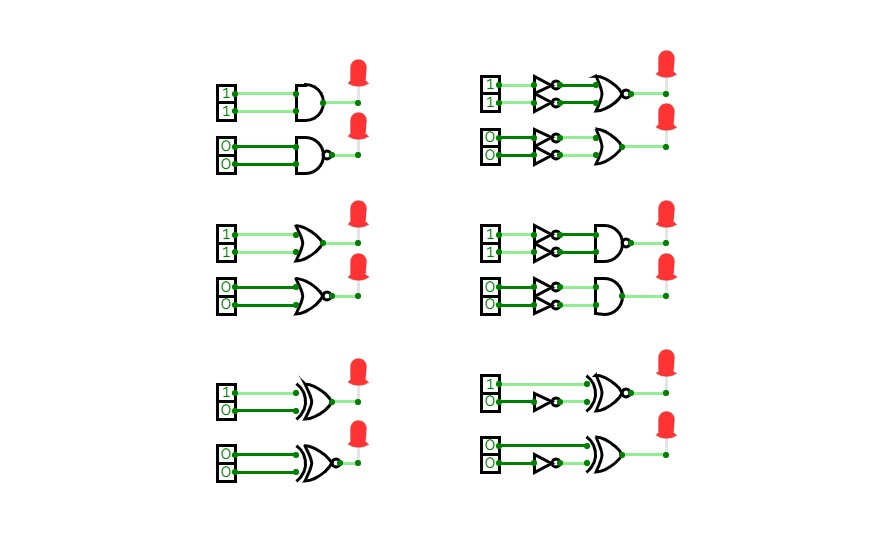

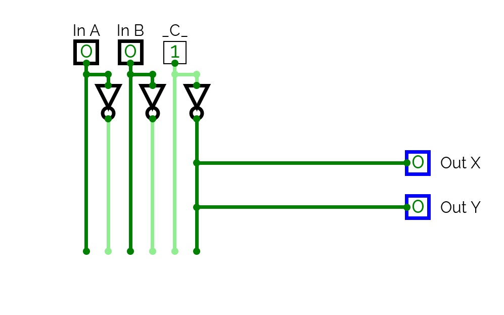
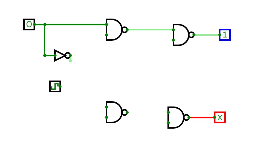
Alternative Gates
Alternative GatesHere, I've done Alternate Gates of all Gates that we have in Alternative Gates. For proving it, I need to get 1 in each and every gate for glowing LED light by giving same inputs in original and alternative gates.
In these alternative gates,
- The NOR gate is an alternative gate to the AND gate, when we give NOT gate to both two inputs. Here, in input, I've given 1 to both inputs. So, in both the AND gate and the alternative gate, output is succeeded in glowing the light.
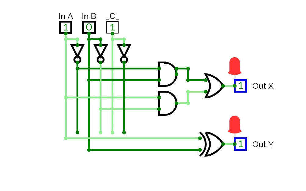
- The OR gate is an alternative gate to the NAND gate, when we give NOT gate to both two inputs. Here, in input, I've given 0 to both inputs. So, in both the NAND gate and the alternative gate, output is succeeded in glowing the light.
- The NAND gate is an alternative gate to the OR gate, when we give NOT gate to both two inputs. Here, in input, I've given 1 to both inputs. So, in both the OR gate and the alternative gate, output is succeeded in glowing light.
- The AND gate is an alternative gate to the NOR gate, when we give NOT gate to both two input. Here, in input, I've given 0 to both the inputs. So, in both the NOR and the alternative gate, output is succeeded in glowing light.
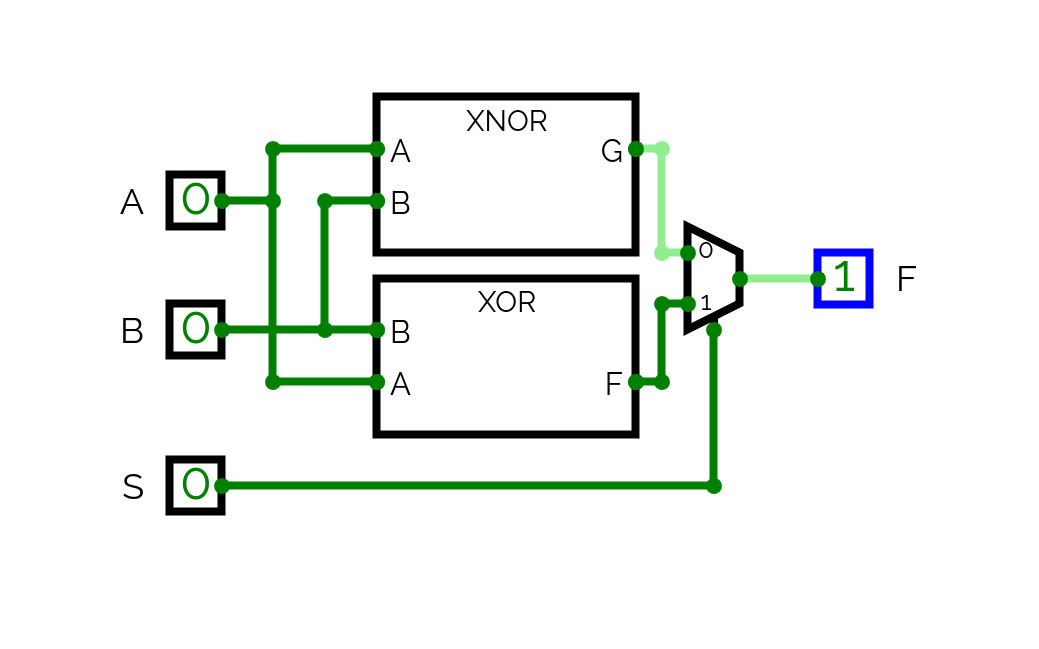
- Ex-NOR gate is an alternative gate to the Ex-OR gate, when we give NOT gate to any one of the input. Here, in input, I've given 1 as 1st input and 0 as the second input to get output as 1. So, in both the Ex-OR and alternative gates are succeeded in glowing the light.
- Ex-OR gate is an alternative gate to the Ex-NOR gate, when we give NOT gate to any one of the input. Here, in input, I've given 0 to both the inputs. So, in both the Ex-NOR and alternative gates are succeeded in glowing the light.