
ELEVATOR
ELEVATOROverview of the Project:-
1. My project is based on the concept of how two elevators can analyze the input of a user, located on a certain floor in a building, and then accordingly decide the response of each elevator to that input.
2. The elevator system can be extended to be used in a building with any number of floors/levels, however, in this project we are assuming that the building only has four floors.
3. The lift will be able to display its location as well as the direction in which it is moving using a 7-segment display.
4. For instance, let us say one of our elevators is on the 1st floor, while the other one is on the 2nd floor. Now, an individual on the 3rd floor calls the elevator. The elevator system will instruct the lift on the 2nd floor, going down, to stop on the 3rd floor, while the lift on the 1st floor will not do any movement.
5. In addition to sequential circuits, we have also used combinational circuits (priority encoder, multiplexer, etc.) to build the project.
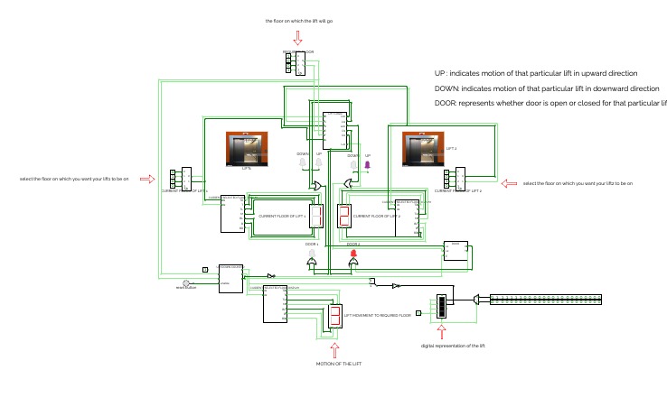
Goals:
- 1. The two LEDs are used for representing the state of their doors, i.e, if the door is open or closed. If the LED of the door is on, that means the door is open while if the LED of the door is off it means that the door is closed.
2 2. The circuits have been designed in such a manner that the lift closer to the floor (on which the user is present) will only move while the other one will remain stationary.
3. In the case of both lifts initially being on the same floor, the same situation occurs,
one lift moves while the other one remains stationary.
Components of the Circuits:-
1. Priority Encoders:-
1.1.The Current floor and the required floor of the lifts are selected using the priority encoder.
1.2. The two priority encoders on the left and right are used to select the current floor of the two lifts. The priority encoder on the left-hand side is used to select the current floor for the lift on the left-hand side and the selected floor is displayed using a seven-segment display and the same procedure for selecting the lift on the right hand side.
1.3. The third priority encoder at the top is used to select the required floor (the floor from which lift is being called).
2. LEDs:-
2.1 There are 6 LEDs being used in the circuit with their function as follows:
2.2 UP: if the up LED of a particular lift is high, it means that the lift is going in an upward direction and if it is low then the lift is not doing any motion in that particular direction.
2.3. DOWN: if the Down LED of a particular lift is high, it means that the lift is going in a downward direction and if it is low then the lift is not doing any motion in that direction.
2.4. DOOR: if the Door LED of a particular lift is high, it means that the door is open for that lift and if it is low then the door is closed for that lift.
3. Seven-Segment Display:-
3.1. There are three sseven-segmentdisplays in the circuit
3.2. The displays on the left and right display the current floor of the lift selected using a priority encoder and the third display at the bottom is a counter.
4. Square LED Matrix:-
The 3x1 matrix displays the floor on which the lift is moving. It is a digital representation of the lift.


