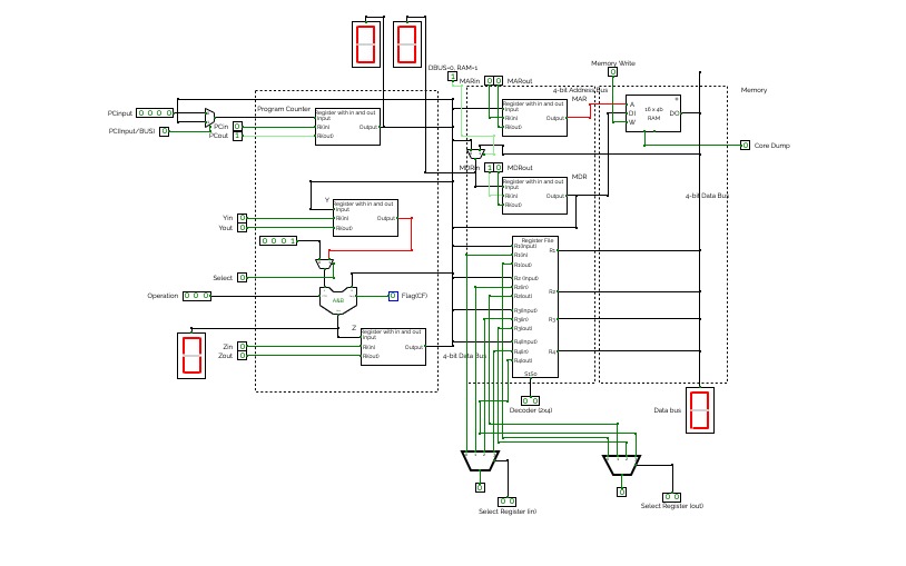

Datapath
DatapathThe datapath is still not finalyzed. It is still in its development phase.
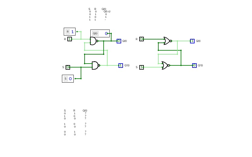
Latches
Latches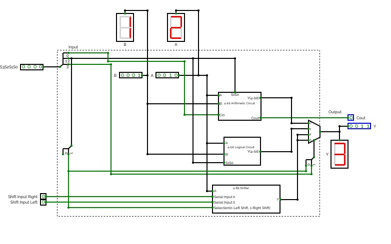
4-bit ALU
4-bit ALU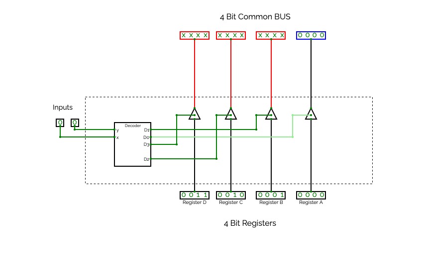
Bus System with Tri-State Buffers
Bus System with Tri-State Buffers
Bus System with Tri-State Buffers
The construction of a bus system with tri-state buffers.
The outputs of four buffers are connected together to form a single bus line. (It must be realized that this type of connection cannot be done with gates that do not have three-state outputs.) The control inputs to the buffers determine which of the four normal inputs will communicate with the bus line. No more than one buffer may be in the active state at any given time. The connected buffers must be controlled so that only one three-state buffer has access to the bus line while all other buffers are maintained in a high- impedance state.
One way to ensure that no more than one control input is active at any given time is to use a decoder, as shown in the circuit. When the enable input of the decoder is 0, all of its four outputs are 0, and the bus line is in a high-impedance state because all four buffers are disabled. When the enable input is active, one of the three-state buffers will be active, depending on the binary value in the select inputs of the decoder.
To construct a common bus for four registers of n bits each using three-state buffers, we need n circuits with four buffers in each as shown in Figure 2. Each group of four buffers receives one significant bit from the four registers. Each common output produces one of the lines for the common bus for a total of n lines. Only one decoder is necessary to select between the four registers.
Each common output produces one of the lines for the common bus for a total of n lines. Only one decoder is necessary to select between the four registers.


