
2*4 DECODER
2*4 DECODERA decoder is a multiple input, multiple output logic circuit that changes codes i/ps into coded o/ps, where both the inputs and outputs are dissimilar for instance n-to-2n, and binary coded decimal decoders. Decoding is essential in applications like data multiplexing, memory address decoding, and 7 segment display. The best example of decoder circuit would be an AND-gate because when all its inputs are “High.”, the output of this gate is “High” which is called “active High output”. As an alternative to AND gate, the NAND gate is connected the output will be “Low” (0) only when all its inputs are “High”. Such o/p is called “active low output”.
2 to 4 Line Decoder
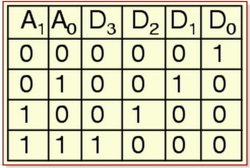
In this type of decoders, decoders have two inputs namely A0, A1, and four outputs denoted by D0, D1, D2, and D3. As you can see in the following truth table – for every input combination, one o/p line is turned on.D0 =A1 A0, ( minterm m0) which corresponds to input 00 D1 =A1 A0, ( minterm m1) which corresponds to input 01 D2 =A1 A0, ( minterm m2) which corresponds to input 10 D3 =A1 A0, ( minterm m3) which corresponds to input 11.
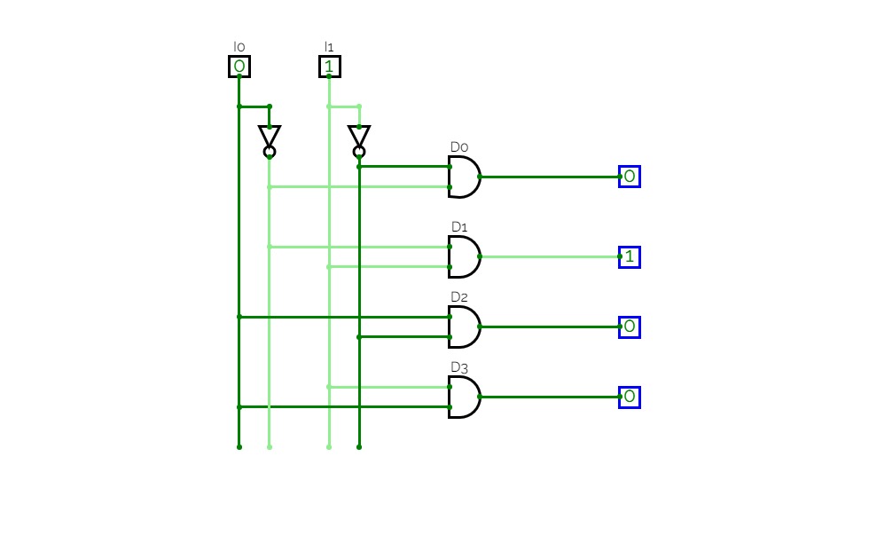
The circuit is implemented using AND gates. In this circuit, the logic equation for D0 is A1/A0, and so on. Thus, each output of the decoder will be generated to the input combination.
Truth Table