
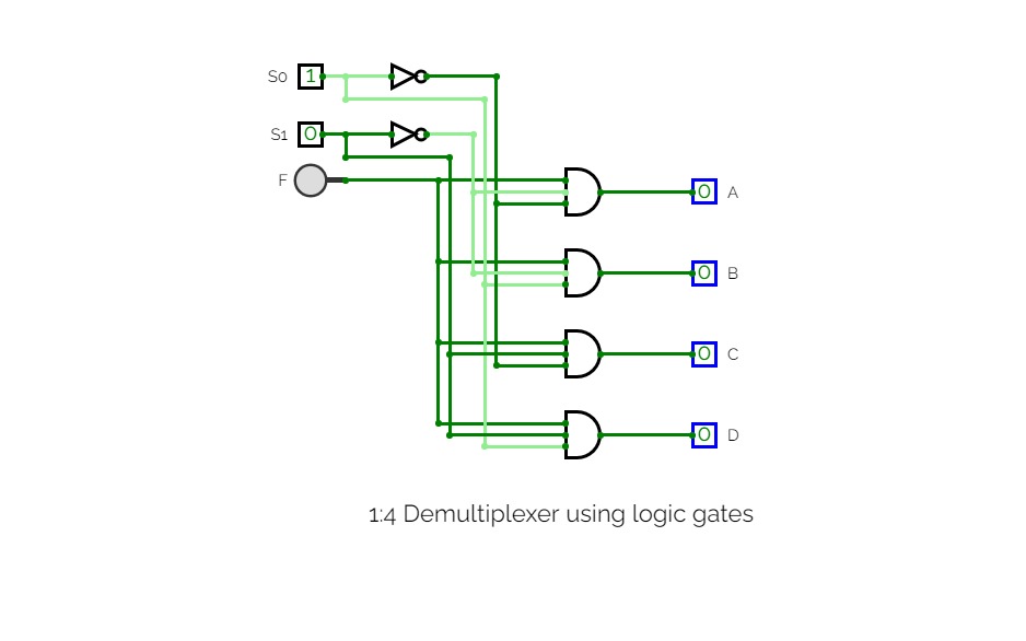
1:4 Demultiplexer using logic gates
1:4 Demultiplexer using logic gatesThe Demultiplexer:-
The demultiplexer takes one single input data line and then switches it to any one of a number of individual output lines one at a time. The demultiplexer converts a serial data signal at the input to a parallel data at its output lines.
*1-to-4 Channel De-multiplexer:-

*Truth Table of Demultiplexer:-
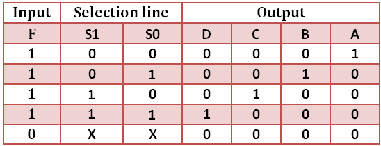
*Diagram:-

*formed using simulator provided.
COUNTERS
COUNTERSSynchronous counter:-
Synchronous Counters are so called because the clock input of all the individual flip-flops within the counter are all clocked together at the same time by the same clock signal ,However, with the Synchronous Counter, the external clock signal is connected to the clock input of EVERY individual flip-flop within the counter so that all of the flip-flops are clocked together simultaneously (in parallel) at the same time giving a fixed time relationship. In other words, changes in the output occur in “synchronisation” with the clock signal.
The result of this synchronisation is that all the individual output bits changing state at exactly the same time in response to the common clock signal with no ripple effect and therefore, no propagation delay.
Here I had used the T Flip Flop for counting 4 bit synchronous counter.
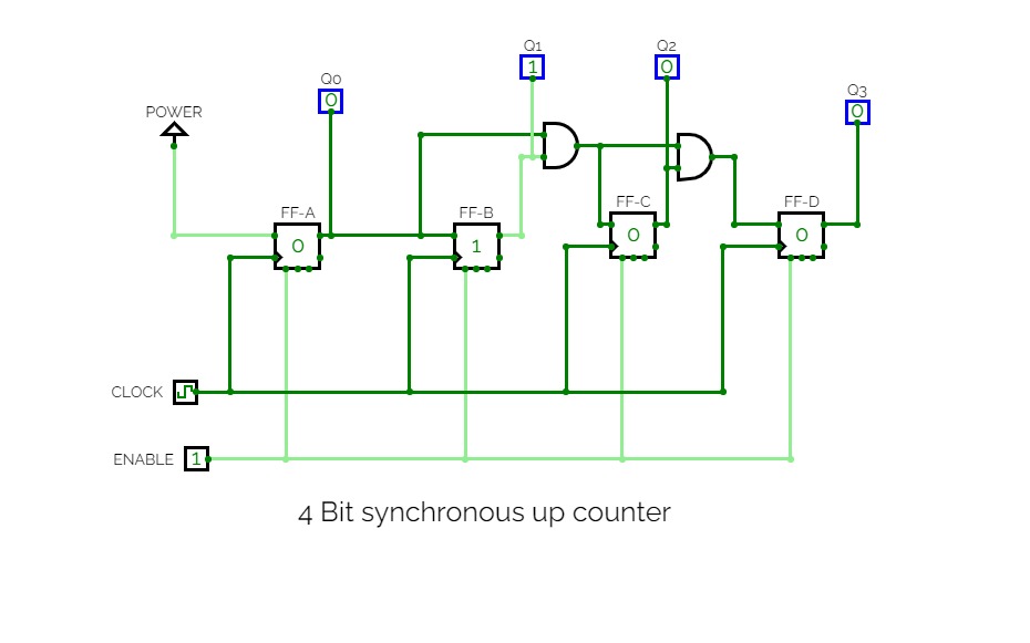
*4-bit Synchronous Up Counter:-
It can be seen above, that the external clock pulses (pulses to be counted) are fed directly to each of the T flip-flops in the counter chain and that T Flip Flops inputs are all tied together in toggle mode, but only in the first flip-flop, flip-flop FFA (LSB) are they connected HIGH, logic “1” allowing the flip-flop to toggle on every clock pulse. Then the synchronous counter follows a predetermined sequence of states in response to the common clock signal, advancing one state for each pulse.
T inputs of flip-flop FFB are connected directly to the output QA of flip-flop FFA, but the T inputs of flip-flops FFC and FFD are driven from separate AND gates which are also supplied with signals from the input and output of the previous stage. These additional AND gates generate the required logic for the T inputs of the next stage.
If we enable each T flip-flop to toggle based on whether or not all preceding flip-flop outputs (Q) are “HIGH” we can obtain the same counting sequence as with the asynchronous circuit but without the ripple effect, since each flip-flop in this circuit will be clocked at exactly the same time.
*Diagram:-

*formed using simulator provided.
Binary 4-bit Synchronous Down Counter:-
As synchronous counters are formed by connecting flip-flops together and any number of flip-flops can be connected or “cascaded” together to form a “divide-by-n” binary counter, the modulo’s or “MOD” number still applies as it does for asynchronous counters so a Decade counter or BCD counter with counts from 0 to 2n-1 can be built along with truncated sequences. All we need to increase the MOD count of an up or down synchronous counter is an additional flip-flop and AND gate across it.
*Diagram:-

*formed using simulator provided.
Excitation table :-

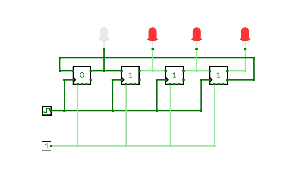

04-Bit Johnson Counter
04-Bit Johnson CounterHere is a full circuit diagram of 04-Bit Johnson Counter.
Feel free to contact me for any further concern.
Thank you.
Regards,
Noman Ali.


