You must login before you can post a comment.
UMLCS L1 AND
0
Stars
170
Views
Author: Peter
Project access type: Public
Description:
L1 AND Gate
Logic Gates
We can represent this process in diagrammatic form by using logic gates to represent the flow of electricity through a transistor. A logic gate is an electric circuit, usually with two inputs and an output. It receives two incoming electric currents, determines whether they are True or False (on or off), and sends on a new, outgoing electric current depending on what it finds. The process of determining the output based on the inputs like this is known as Boolean logic.
The AND gate
This is an AND logic gate, which represents a small circuit configured in a particular way to give a particular result. You can see the inputs on the left represented by lines going into the AND logic gate symbol. What do you think this means?
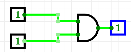
The AND gate has two inputs and one output. Both have to be True (or on) to produce an output of True. In the example above both inputs are set to True, which results in a True output.
What if only one was True? Like this:
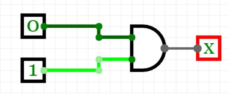
What do you think the output (denoted by X here) would be this time?
In the case of an AND gate, if only one of the inputs was switched on then the output is 0. And if neither input is switched on, you would be right in assuming that there is again an output of 0. Both the first input and the second input have to be 1 to achieve a True (or 1, or on) output.
Created: May 16, 2019
Updated: Jun 30, 2023


Comments