You must login before you can post a comment.
AND AND NOT
0
Stars
505
Views
Author: Peter
Project access type: Public
Description:
Another example
The next example consists of three logic gates and has the added complexity of the bottom input (B) going through both logic gates. Again, we have used intermediate values to show the different steps in the circuit.
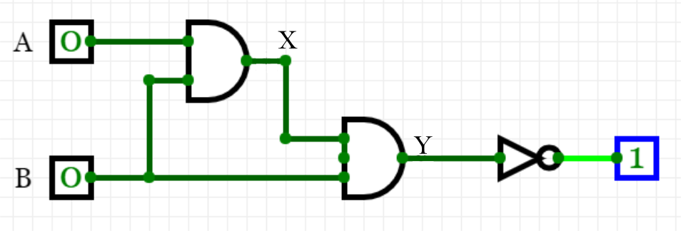
Condition 1: Both inputs A and B are 0.
This can be traced first through the top AND logic gate, with the result that X is 0. This then becomes the top input for the second logic gate, which combines with B as an input. Again, as both are 0, Y is 0. However, before the circuit is complete it goes through a NOT gate, which leads to an output of 1.
Condition 2: This time A is 0 and B is 1.
From the top AND logic gate, X is 0. The inputs to the seconnd logic gate, X and B, are 0 and 1, so Y again becomes 0. Again, the final gate (NOT) leads to an output of 1.
Condition 3: This time A is 1 and B is 0.
This gives X as 0, and Y becomes 0. Yet again, the final gate (NOT) leads to an output of 1.
Condition 4: This time A is 1 and B is also 1.
This can be traced first through the top AND logic gate, with the result that X is 1. The two inputs for the second logic gate are both 1, so Y is also 1. However, before the circuit is complete the NOT gate leads to an ouput of 0.
The resultant truth table looks like this:
ABXYOutput 00001 01001 10001 11110You have now met the AND, OR, NOT, and XOR gates, and used truth tables and combining logic gates to produce logic circuits. You’ve worked through the Boolean logic involved in order to work out the outputs from these circuits. The next step is to complete a quiz on logic gates to check your understanding.
Thoughts
Created: May 16, 2019
Updated: Jun 30, 2023


Comments