You must login before you can post a comment.
4-bit ripple carry adder
0
Stars
537
Views
Author: TMSY Tutorials
Project access type: Public
Description:
AIM:
To write the Verilog code for a 4-bit ripple carry adder and obtain the simulation, and synthesis results using Xilinx ISE 14.7 tool.
APPARATUS:
- PC with Windows 10
- Xilinx ISE 14.7 Tool
THEORY:
Half Adder
A half-adder is a digital circuit that performs the addition of two binary digits and produces a sum and a carry. Unlike a full adder, a half adder does not take into account any carry input from previous stages of addition.
A half adder has two inputs, a and b, and two outputs, carry and sum.
The truth table of a half-adder is as follows:
abcarrysum0000010110011110In this truth table, the ‘sum’ output is the XOR of the input bits ‘a’ and ‘b’, while the ‘carry’ output is the AND of the input bits ‘a’ and ‘b’.
A half-adder can be implemented using logic gates such as XOR and AND gates. However, a half adder cannot handle a carry input from previous stages of addition, and hence it is not sufficient for performing multi-bit addition. A full adder, on the other hand, can handle carry input from previous stages and can be used for multi-bit addition.
Full Adder
A full adder is a digital circuit that performs the addition of two binary numbers along with a carry input. It has three inputs: a, b, and cin (carry input), and two outputs: sum and carry.
The truth table of a full adder is as follows:
abcincarrysum0000000101010010111010001101101101011111In this truth table, ‘a’ and ‘b’ are the two input bits, ‘cin’ is the carry input, ‘sum’ is the sum output, and ‘carry’ is the carry output. The full adder circuit can be implemented using logic gates such as AND, OR, and XOR gates. In this truth table, ‘a’ and ‘b’ are the two input bits, ‘cin’ is the carry input, ‘sum’ is the sum output, and ‘carry’ is the carry output. The full adder circuit can be implemented using logic gates such as AND, OR, and XOR gates.
A full adder can be used as a building block for constructing larger adders such as a ripple-carry adder, carry-lookahead adder, or carry-select adder.
4-bit Ripple Carry Adder
A 4-bit ripple carry adder is a digital circuit that performs the addition of two 4-bit binary numbers using four full adders in a chain, with the carry output of each full adder connected to the carry input of the next full adder. The carry input of the least significant full adder is set to 0.
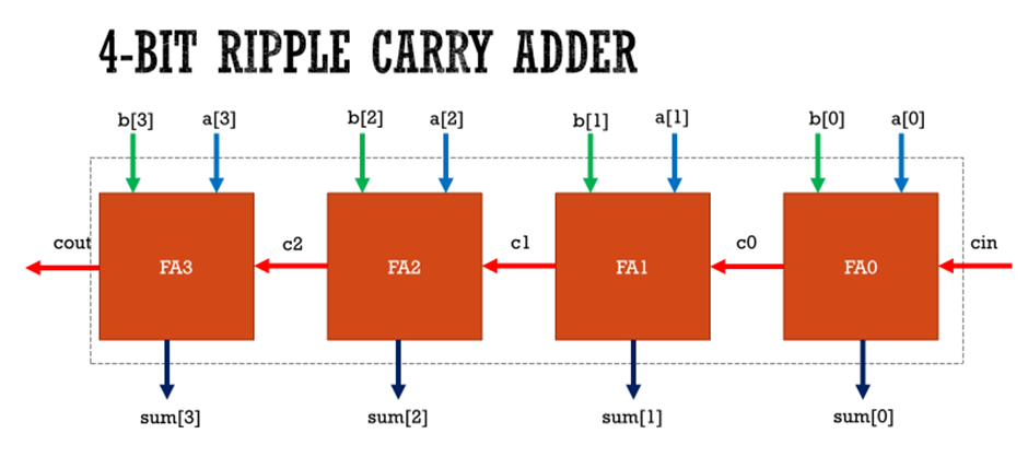
Figure 1 Block Diagram of 4-bit Ripple Carry Adder
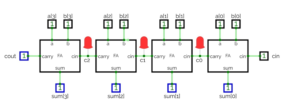
Figure 2 Simulated Logic Diagram of 4-bit Ripple Carry Adder
In this circuit, a0-A3 and b0-B3 are the four-bit binary numbers to be added, and s0-s3 are the four-bit binary sum outputs. c0-c2 are the carry inputs to the full adders, and cout is the carry output from the last full adder.
The operation of a 4-bit ripple carry adder can be understood as follows:
- The least significant bits a0 and b0 are added using a full adder, producing a sum bit s0 and a carry bit c0.
- The next bits a1 and b1 are added using a full adder, along with the carry bit c0 from the previous stage, producing a sum bit s1 and a carry bit c1.
- The next bits a2 and b2 are added using a full adder, along with the carry bit c1 from the previous stage, producing a sum bit s2 and a carry bit c2.
- The most significant bits a3 and b3 are added using a full adder, along with the carry bit c2 from the previous stage, producing a sum bit s3 as the final result.
- The carry propagation in a ripple carry adder can lead to longer propagation delay and increased circuit complexity compared to other adder architectures, such as carry-lookahead adders or carry-select adders.
PROGRAM:
SOURCE CODE
Step 1: 1 – Bit Full Adder Verilog Source code
module fulladder(sum,carry,a,b,cin); output sum; output carry; input a; input b; input cin; xor x1(w1,a,b); and x2(w2,a,b); xor x3(sum,w1,cin); and x4(w3,w1,cin); or x5(carry,w2,w3); endmodule
Step 2: 4 – Bit Ripple Carry Adder or 4 – Bit Binary Adder Verilog Source code
module ripplecarryadder_4bit(sum,cout,a,b,cin); output [3:0]sum; output cout; input [3:0]a,b; input cin; wire c0,c1,c2; fulladder FA0(sum[0],c0,a[0],b[0],cin); fulladder FA1(sum[1],c1,a[1],b[1],c0); fulladder FA2(sum[2],c2,a[2],b[2],c1); fulladder FA3(sum[3],cout,a[3],b[3],c2); endmodule
TEST BENCH:
module ripplecarryadder_4bit_TB; // Inputs reg [3:0] a; reg [3:0] b; reg cin; // Outputs wire [3:0] sum; wire cout; ripplecarryadder_4bit uut(sum,cout,a,b,cin); initial begin $monitor($time,"sum=%b,cout=%b,a=%b,b=%b,cin=%b",sum,cout,a,b,cin); // Initialize Inputs a = 0; b = 0; cin = 0; end always #20 a=a+1; always #10 b=b+1; always #05 cin=cin+1; endmodule
RESULT:
The Synthesis and Simulation results for the 4-bit Ripple Carry Adder are obtained using the Xilinx ISE 14.7 tool.
Created: Apr 01, 2024
Updated: Apr 01, 2024


Comments