You must login before you can post a comment.
Author: edu4school
Forked from: David Piña/synchronous binary counter and down
Project access type: Public
Description:
Synchronous Counters
If all the flip-flops receive the same clock signal, then that counter is called as Synchronous counter. Hence, the outputs of all flip-flops change affect
at the same time.
Now, let us discuss the following two counters one by one.
- Synchronous Binary up counter
- Synchronous Binary down counter
Synchronous Binary Up Counter
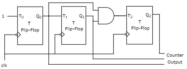
An ‘N’ bit Synchronous binary up counter consists of ‘N’ T flip-flops. It counts from 0 to 2𝑁 − 1. The block diagram of 3-bit Synchronous binary up counter is shown in the following figure.

The 3-bit Synchronous binary up counter contains three T flip-flops & one 2-input AND gate. All these flip-flops are negative edge triggered and the outputs of flip-flops change affect
synchronously. The T inputs of first, second and third flip-flops are 1, Q0 & Q1Q0
respectively.
The output of first T flip-flop toggles for every negative edge of clock signal. The output of second T flip-flop toggles for every negative edge of clock signal if Q0
is 1. The output of third T flip-flop toggles for every negative edge of clock signal if both Q0 & Q1
are 1.
Synchronous Binary Down Counter
An ‘N’ bit Synchronous binary down counter consists of ‘N’ T flip-flops. It counts from 2𝑁 − 1 to 0. The block diagram of 3-bit Synchronous binary down counter is shown in the following figure.

The 3-bit Synchronous binary down counter contains three T flip-flops & one 2-input AND gate. All these flip-flops are negative edge triggered and the outputs of flip-flops change affect
synchronously. The T inputs of first, second and third flip-flops are 1, Q0′ &' Q1′Q0′
respectively.
The output of first T flip-flop toggles for every negative edge of clock signal. The output of second T flip-flop toggles for every negative edge of clock signal if Q0′
is 1. The output of third T flip-flop toggles for every negative edge of clock signal if both Q1′ & Q0′ are 1.
Created: Dec 07, 2023
Updated: Dec 09, 2023


Comments