John W McMichen
Member since: 1 year
Educational Institution: Cleveland State Community College
Country: United States
NOR Gate
NOR Gate
NAND RS latch
NAND RS latch
NAND edge-triggered RS flip flop
NAND edge-triggered RS flip flop
NAND Gate with Clock and LED
NAND Gate with Clock and LED
AND Gate
AND Gate
OR Gate
OR Gate
NAND Gate
NAND Gate
DeMorgan's Theorem 1
DeMorgan's Theorem 1
7 segment display hex
7 segment display hex
Figure 4-21
Figure 4-21
Negative Edge Triggered Clock
Negative Edge Triggered Clock
Half Adder Circuit
Half Adder Circuit
Positive Edge-triggered clock
Positive Edge-triggered clock
Full Adder Circuit
Full Adder Circuit
Full Subtractor Circuit
Full Subtractor Circuit
D Flip-Flop with positive edge triggered clock
D Flip-Flop with positive edge triggered clock
4 AND
4 AND
4 input AND
4 input AND
JK FF c PRE & CLR
JK FF c PRE & CLR
JK FF c PRE & CLR
JK FF c PRE & CLR
ROM access circuit
ROM access circuit
NAND JK FF backup
NAND JK FF backup
Ripple Up, Down Counter
Ripple Up, Down Counter
Hex 7 segment display
Hex 7 segment display
Roulette Wheel or Marquee Sign
Roulette Wheel or Marquee Sign
JK FF with subcircuit
JK FF with subcircuit
JK FF active low preset and clear
JK FF active low preset and clear
Recirculating Shift Register D flip flops
Recirculating Shift Register D flip flops
D Flip-Flop with clock
D Flip-Flop with clock
Decade Ripple Counter
Decade Ripple Counter
D Flip-Flop
D Flip-Flop
Repeated Addition Multiplier
Repeated Addition Multiplier
AND/OR circuit with clock
AND/OR circuit with clock
2's Complement Adder/Subtractor
2's Complement Adder/Subtractor
4 Bit SRAM Memory
4 Bit SRAM Memory
16 Bit Column Row Decoder
16 Bit Column Row Decoder
Synchronous Down Counter
Synchronous Down Counter
Serial Load Shift Register, D flip flops
Serial Load Shift Register, D flip flops
RAM Circuit
RAM Circuit
8 bit binary to decimal converter
8 bit binary to decimal converter
Repeat add multiplier (1)
Repeat add multiplier (1)
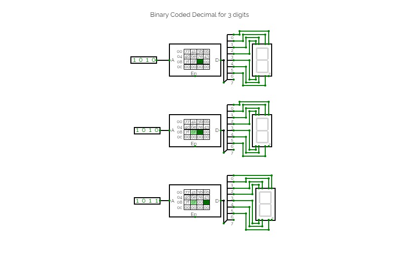
Binary Coded Decimal Circuit for 3 digits
Binary Coded Decimal Circuit for 3 digits
JK Master Slave Flip Flop
JK Master Slave Flip Flop
JK Master-Slave PRE and CLR
JK Master-Slave PRE and CLR
Password Keyboard Project
Password Keyboard Project
Half Subtractor
Half Subtractor
BCD Adder
BCD Adder
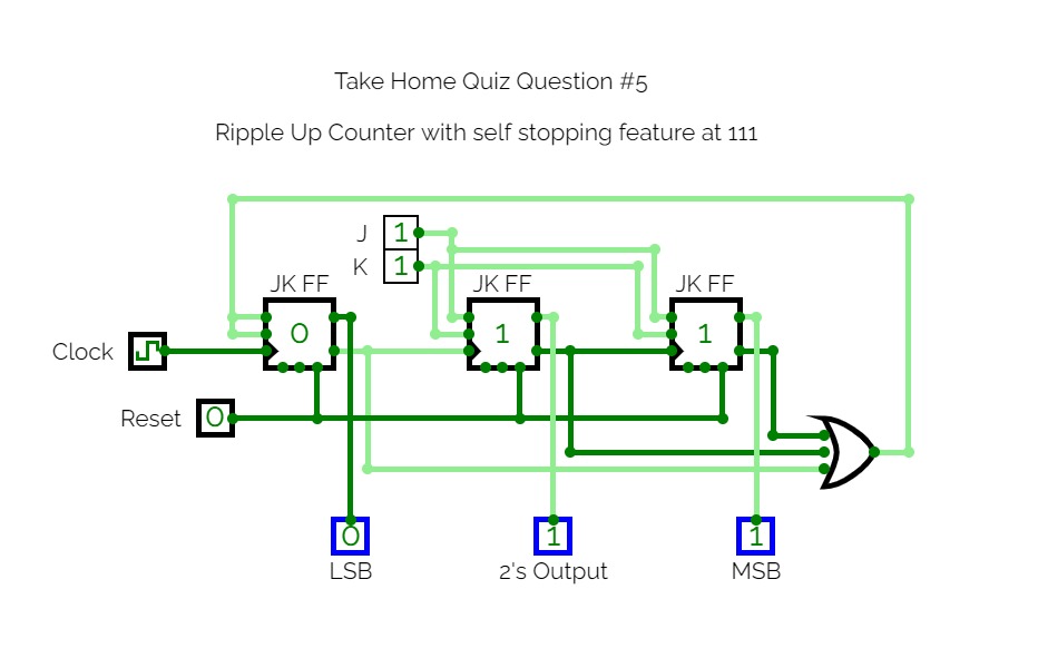
Take Home Quiz Question #5
Take Home Quiz Question #5
Junk circuit
Junk circuit
Synchronous Up Counter
Synchronous Up Counter
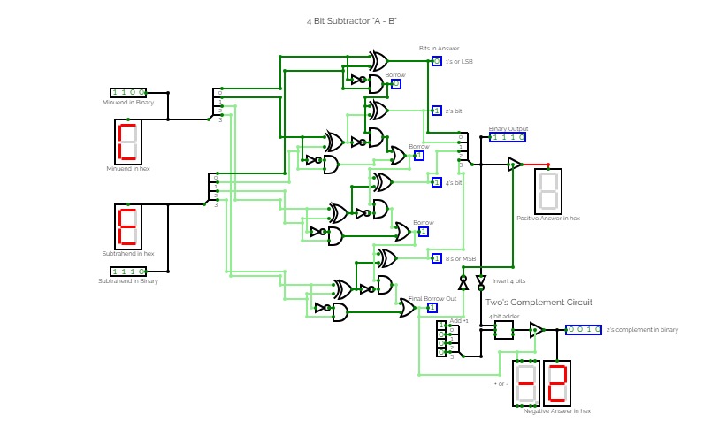
4 Bit Subtractor: "A - B"
4 Bit Subtractor: "A - B"
4 Bit Adder: "A + B"
4 Bit Adder: "A + B"
J-K Flip Flop with inverted clock
J-K Flip Flop with inverted clock
XOR Gate Equivalent Circuit
XOR Gate Equivalent Circuit
Ripple Down Counter
Ripple Down Counter
AND Gate with Clock and LED
AND Gate with Clock and LED
XOR Gate with Clock and LED
XOR Gate with Clock and LED
Inverter Gate with Clock and LED
Inverter Gate with Clock and LED
NOT Gate (Inverter)
NOT Gate (Inverter)
NOR Gate with Clock and LED
NOR Gate with Clock and LED
DeMorgan's Theorem 2
DeMorgan's Theorem 2
NAND RS flip-flop with clock
NAND RS flip-flop with clock
OR Gate with CLock and LED
OR Gate with CLock and LED
Serial Waveform Shift Register D flip flops
Serial Waveform Shift Register D flip flops
Parallel Input, Parallel Output Register, D flip flops
Parallel Input, Parallel Output Register, D flip flops
Shift and Add Multiplier
Shift and Add Multiplier
Take Home Quiz Question #1
Take Home Quiz Question #1
Take Home Quiz Question #2
Take Home Quiz Question #2
Take Home Quiz Question #3
Take Home Quiz Question #3
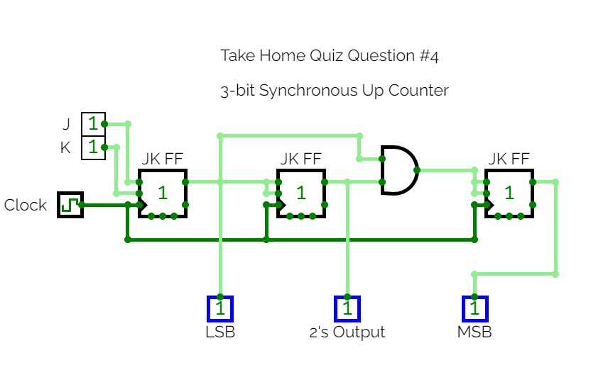
Take Home Quiz Question #4
Take Home Quiz Question #4
Untitled
Untitled
OR and NOR Gate Waveforms
OR and NOR Gate Waveforms
Double Inverter Circuit
Double Inverter Circuit
4 input And gate
4 input And gate
XOR, XNOR Gate Waveform
XOR, XNOR Gate Waveform
NOT Gate Waveforms
NOT Gate Waveforms
NOR Gate Equivalent
NOR Gate Equivalent
AND Gate Equivalent Circuit
AND Gate Equivalent Circuit
NAND Gate Equivalent Circuit
NAND Gate Equivalent Circuit
NOT Gate Equivalent Circuit
NOT Gate Equivalent Circuit
XNOR Gate Equivalent Circuit
XNOR Gate Equivalent Circuit
OR Gate Equivalent Circuit
OR Gate Equivalent Circuit
AND NAND Gate Waveforms
AND NAND Gate Waveforms
7 segment hex display
7 segment hex display
Waveforms of the OR and NOR Gates
Waveforms of the OR and NOR Gates
8-Bit Up Counter in Hex
8-Bit Up Counter in Hex
Equivalent XOR Gate
Equivalent XOR Gate
J-K Positive Edge Trigger Flip Flop
J-K Positive Edge Trigger Flip Flop
Binary to Hex to Decimal Converter
Binary to Hex to Decimal Converter


