Johan Thomas
Member since: 1 year
Educational Institution: Not Entered
Country: Not Entered
HA
HA
FA
FA
HS
HS
HF
HF
PISO SHIFT REGISTER
PISO SHIFT REGISTER
4 bit adder
4 bit adder
2x2 multiplier
2x2 multiplier
BCD to 4521 using NAND Logic with Don
BCD to 4521 using NAND Logic with Don
SIPO
SIPO
Task I (POS) implemented using Decoder Active Low logic
Task I (POS) implemented using Decoder Active Low logic
Untitled
Untitled
CAT2 B2 Q2
CAT2 B2 Q2
CAT2 B1 Q5
CAT2 B1 Q5
CAT2 B1 Q3
CAT2 B1 Q3
CAT2 B1 Q4
CAT2 B1 Q4
CAT 2 B1 Q4
CAT 2 B1 Q4
CAT2 B1 Q5
CAT2 B1 Q5
CAT2 B2 Q3
CAT2 B2 Q3
CAT2 B2 Q4
CAT2 B2 Q4
CAT2 B2 Q5
CAT2 B2 Q5
Untitled
Untitled
Untitled
Untitled
Untitled
Untitled
Untitled
Untitled
Untitled
Untitled
Binary to gray code POS
Binary to gray code POS
BCD to 4521 using AOI Logic with Don
BCD to 4521 using AOI Logic with Don
SOP canonical expression of MUX and circuit implemented in MUX
SOP canonical expression of MUX and circuit implemented in MUX
2:1 MUX Circuit using SOP Equation
2:1 MUX Circuit using SOP Equation
POS canonical expression of MUX and circuit implemented in MUX
POS canonical expression of MUX and circuit implemented in MUX
SOP canonical expression of MUX and circuit implemented in MUX
SOP canonical expression of MUX and circuit implemented in MUX
2:1 MUX Circuit using SOP Equation
2:1 MUX Circuit using SOP Equation
2:1 MUX Circuit using POS Equation
2:1 MUX Circuit using POS Equation
2:1 MUX Circuit using POS Equation
2:1 MUX Circuit using POS Equation
2:1 MUX Circuit using POS Equation
2:1 MUX Circuit using POS Equation
2:1 MUX Circuit using SOP Equation
2:1 MUX Circuit using SOP Equation
2:1 MUX Circuit using POS Equation
2:1 MUX Circuit using POS Equation
2:1 MUX Circuit using POS Equation
2:1 MUX Circuit using POS Equation
Untitled
Untitled
8x1_mux_22bce2157
8x1_mux_22bce2157
8x1 multiplexer using two 4x1 and one 2x1
8x1 multiplexer using two 4x1 and one 2x1
8x1 multiplexer using two 4x1 and one 2x1
8x1 multiplexer using two 4x1 and one 2x1
Untitled
Untitled
AOI logic circuit of 4:2 encoder
AOI logic circuit of 4:2 encoder
AOI logic circuit of 2:4 Decoder
AOI logic circuit of 2:4 Decoder
NAND logic circuit of 2:4 Decoder
NAND logic circuit of 2:4 Decoder
AOI logic circuit of 2:4 Decoder
AOI logic circuit of 2:4 Decoder
INTERNAL CIRCUIT OF 1:2 DEMUX USING TWO INPUT NAND GATE
INTERNAL CIRCUIT OF 1:2 DEMUX USING TWO INPUT NAND GATE
Untitled
Untitled
4 : 1 multiplexer
4 : 1 multiplexer
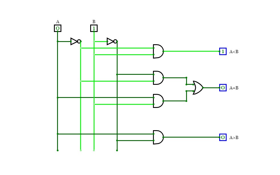
1 Bit Comparator
1 Bit Comparator
4 : 1 multiplexer
4 : 1 multiplexer
newproject
newproject
CAT B1 Q5
CAT B1 Q5
Q3_DA_USING_MUX
Q3_DA_USING_MUX
7 Segment Decoder common cathode
7 Segment Decoder common cathode
BCD to 4521 NOR with dc
BCD to 4521 NOR with dc
7 segment display using 1:16 decoder
7 segment display using 1:16 decoder
Untitled
Untitled
Untitled
Untitled
7 segment display using 1:16 decoder
7 segment display using 1:16 decoder
CAT1 B2 Q1
CAT1 B2 Q1
new1
new1
new2
new2
CAT 1 B1 Q1
CAT 1 B1 Q1
CAT 1 B1 Q1
CAT 1 B1 Q1
Binary to Gray code NOR
Binary to Gray code NOR
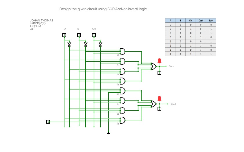
Design the given circuit using SOP (And-or-invert) logic.
Design the given circuit using SOP (And-or-invert) logic.
Binary to Gray code SOP
Binary to Gray code SOP
Untitled
Untitled
Untitled
Untitled
Untitled
Untitled
Untitled
Untitled
Parallel in Parallel Out Shift Register
Parallel in Parallel Out Shift Register
CAT 1 B2 Q2
CAT 1 B2 Q2
CAT 1 B1 Q4
CAT 1 B1 Q4
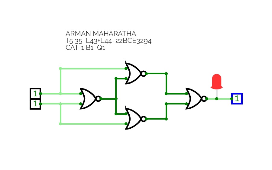
CAT-1 B1 Q2
CAT-1 B1 Q2
CAT1 B2 Q5
CAT1 B2 Q5
CAT1 B2 Q4
CAT1 B2 Q4
BCD to 4521 OAI with dc
BCD to 4521 OAI with dc
demux with dont care
demux with dont care
BCD to 4521 using Decoder with Don
BCD to 4521 using Decoder with Don
1:2 Demux using NAND logic
1:2 Demux using NAND logic
Binary to 7 Segment
Binary to 7 Segment
cat 2 b1 q2
cat 2 b1 q2
Task I (POS) implemented using Decoder Active High logic
Task I (POS) implemented using Decoder Active High logic
Task I (SOP) implemented using Decoder Active High logic
Task I (SOP) implemented using Decoder Active High logic
2:1 MUX Circuit using SOP Equation
2:1 MUX Circuit using SOP Equation
Serial In Serial Out Shift Register - D flip flop
Serial In Serial Out Shift Register - D flip flop
2:1 MUX Circuit using POS Equation
2:1 MUX Circuit using POS Equation
7 Seg Decoder COMMON ANODE
7 Seg Decoder COMMON ANODE
1:2 Demux using NAND logic
1:2 Demux using NAND logic
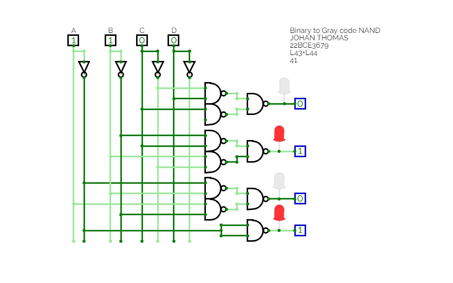
Binary to Gray code NAND
Binary to Gray code NAND


