
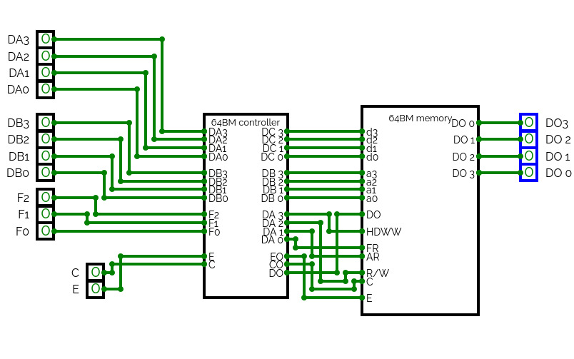
_2.jpg)
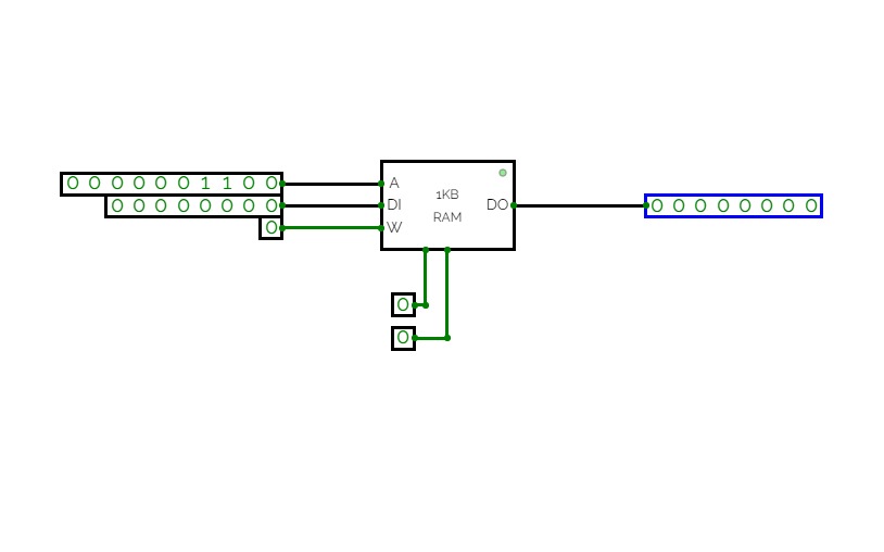
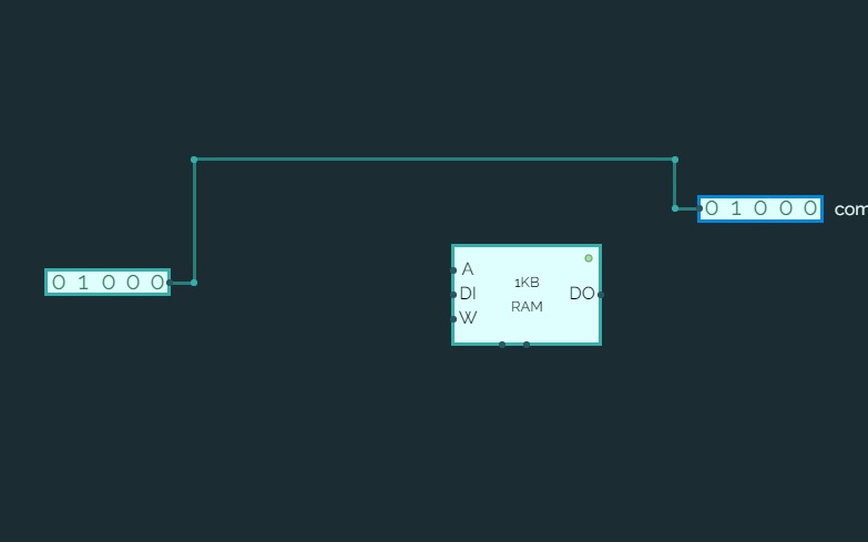
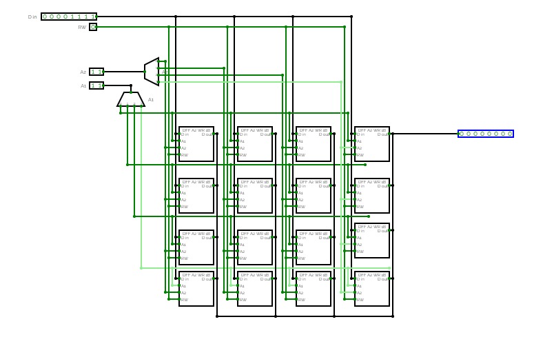
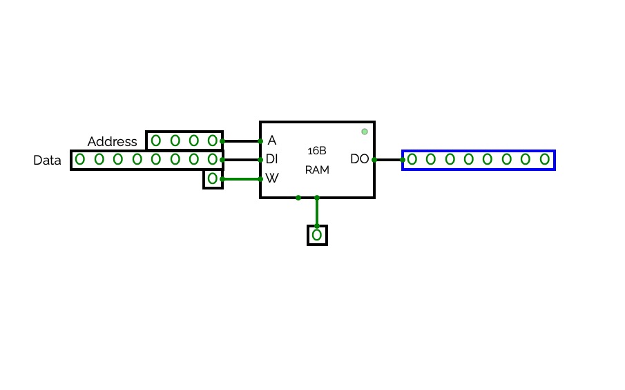
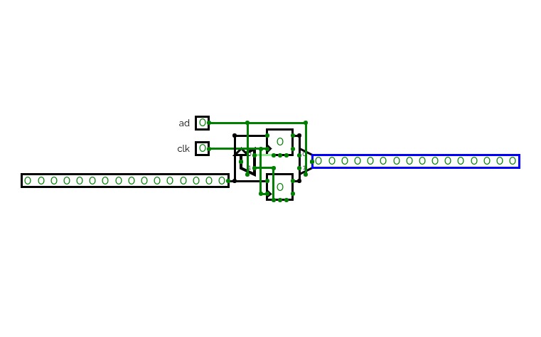
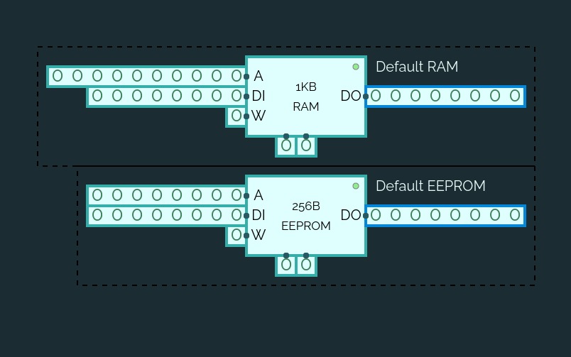
Static RAM
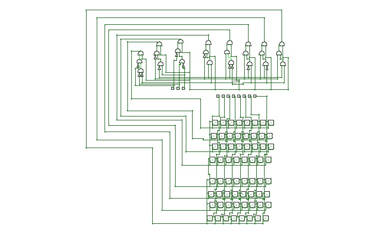
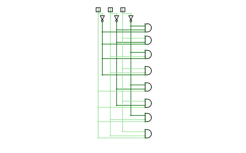
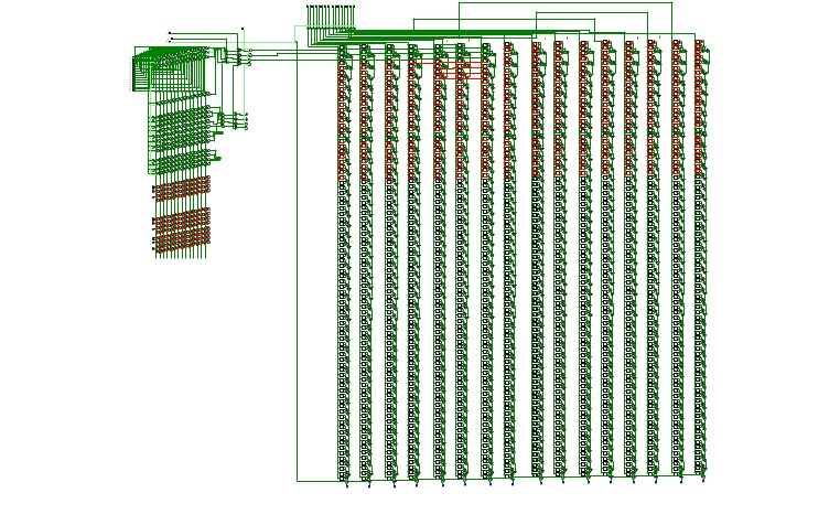
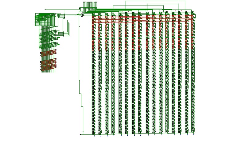
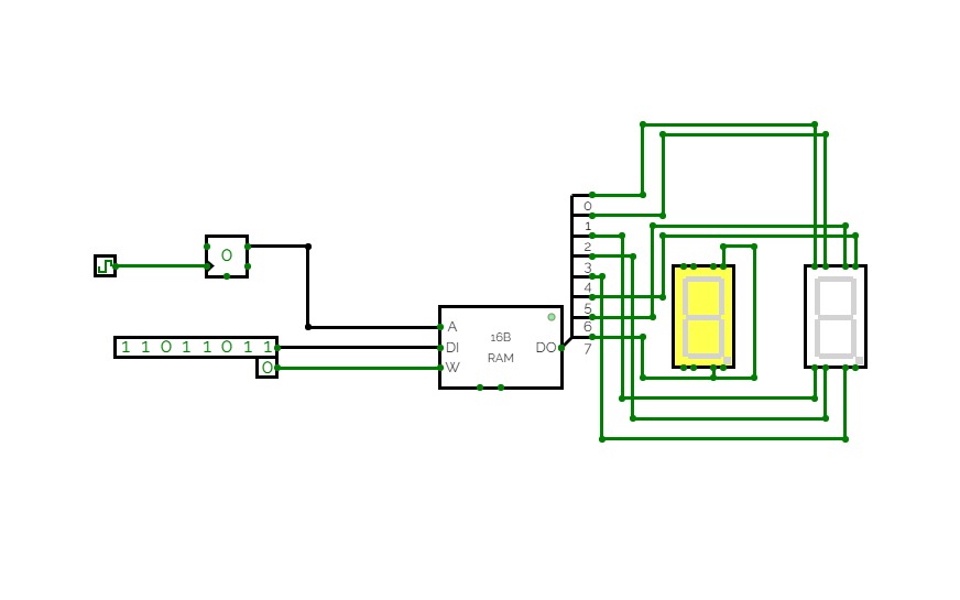
Static RAMEmulation of 'static RAM', which is essentially built from D-type flip-flops.
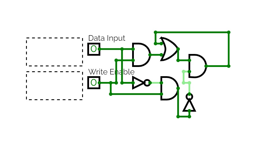
The principal difference between this and the standard RAM component in CircuitVerse is that all the static RAMs in this project are edge-triggered for write (reading is asynchronous).
The basic building block is the 1x8-bit SRAM circuit - a single byte of memory, built from an 8-bit D-type flip flop.
16 of these are then used in a 4 x 4 grid to build the 16x8-bit SRAM circuit, which now includes the necessary 4-bit address decoding circuitry.
16 of these are then used in a 4 x 4 grid to build the 256x8-bit SRAM circuit.
The pattern could be applied recursively to build, in turn, a 4KB, 64KB, 1MB chip, and so on.
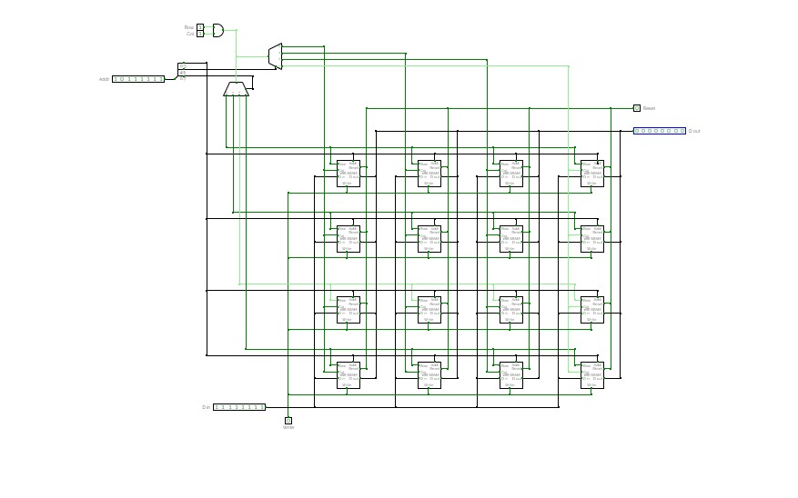
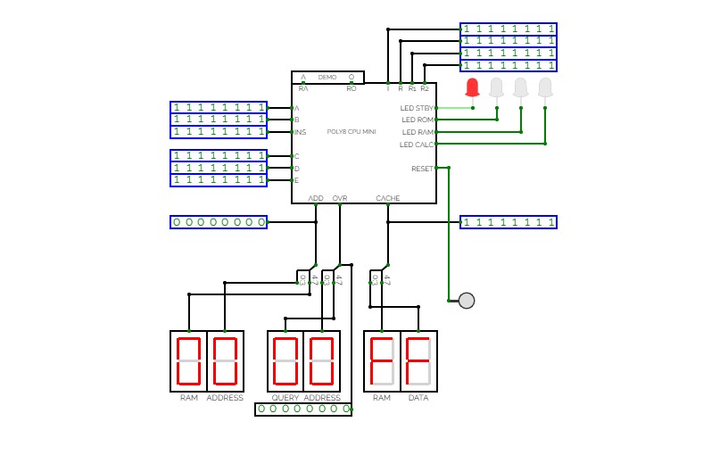
Experiment 3 - RAM Design
Experiment 3 - RAM Design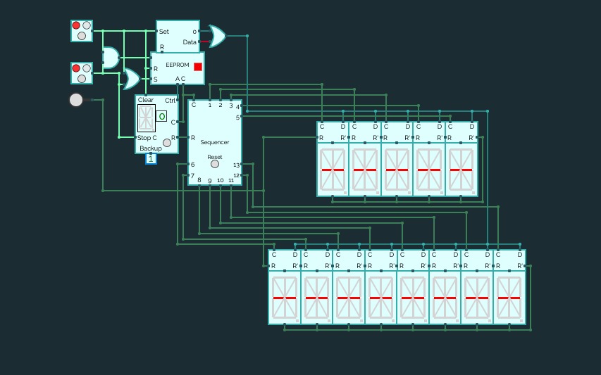

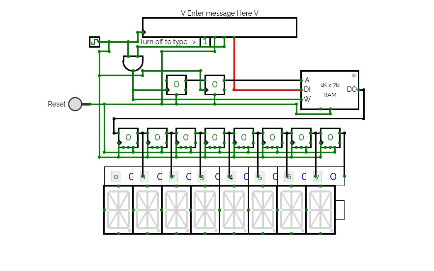
Asynchronous 16 - Segment Array
Asynchronous 16 - Segment ArrayInstructions
Set both buttons to off (RED). Now reset the sequencer and turn on button 1 and 2 (set to GREEN).
Button 1 controls the data fed to the displays.
OFF = Clear all displays ON = Programmed message
Button 2 controls the clock.
To change the message, dump the core or reset the EEPROM and rewrite the suitable data for the 16-Segment Displays. If the new message contains lesser or more letters/numbers to show, make suitable changes to the Sequencer and change the number of displays used.
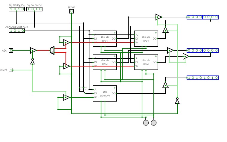

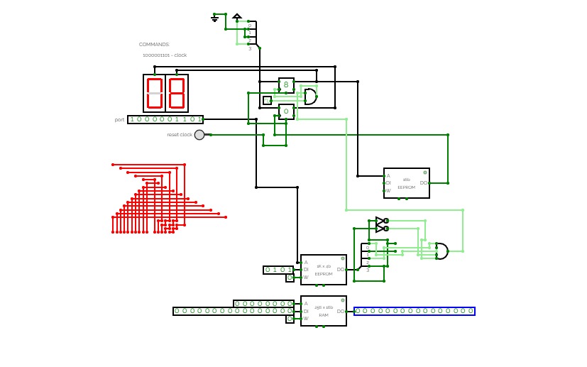
simple computer
simple computersimple computer with clock
commands:
10001: Clock
00011: Do a OR operation*
01101: Do a AND operation*
01110: Do a NAND operation*
01001: RAM edit/read**
*Use number inputs too do the logic.
**Use data inputs edit/assign values to an 8-bit RAM. Use the R/W pin to read & write.
Specs:
RAM:
1KB (as seen in photo)

Clock:
2HZ (as seen in photo)

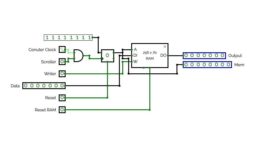
BRWD: BINARY READER AND WRITER DEVICE
Specs:
7-bit RAM
8-bit Memory
How to use:
1. To start writing, set your clock speed, and turn on the "Writer" switch.
2. To scroll through the memory, turn on the "Scroll" switch. Press "Reset" if you are ready to read.
3. Turn the "Writer" switch off, and turn on "Scroll" to start reading the binary.
4. Then when you're done, press "Reset RAM" to reset your writing.
Better 16-Segment Rolling Display
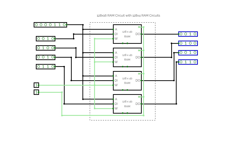
Better 16-Segment Rolling DisplayAn improvement on my previous design of a rolling 16-Segment display, this time using RAM to store undisplayed letters. Note that a space will automatically be placed before your message each time. (If you see how I could prevent this, please let me know.)

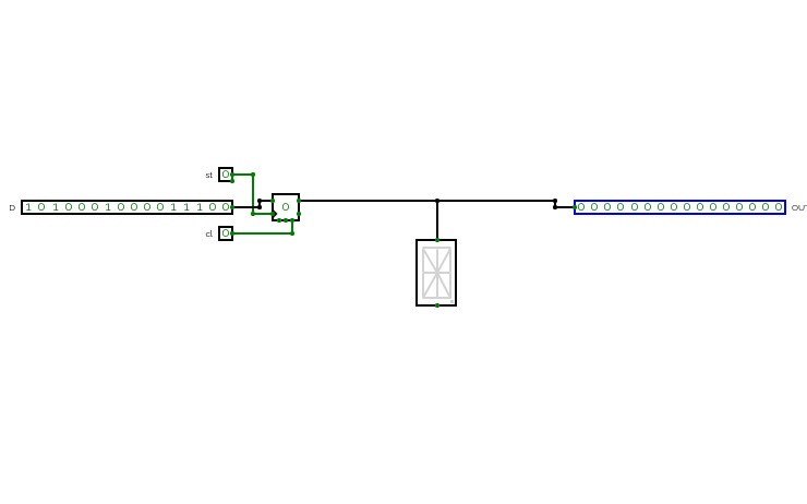
RAM counter 7 segment display
RAM counter 7 segment display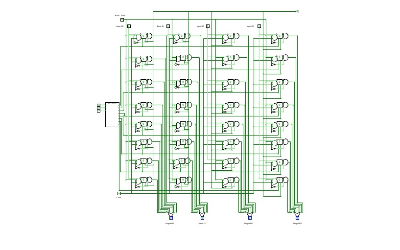
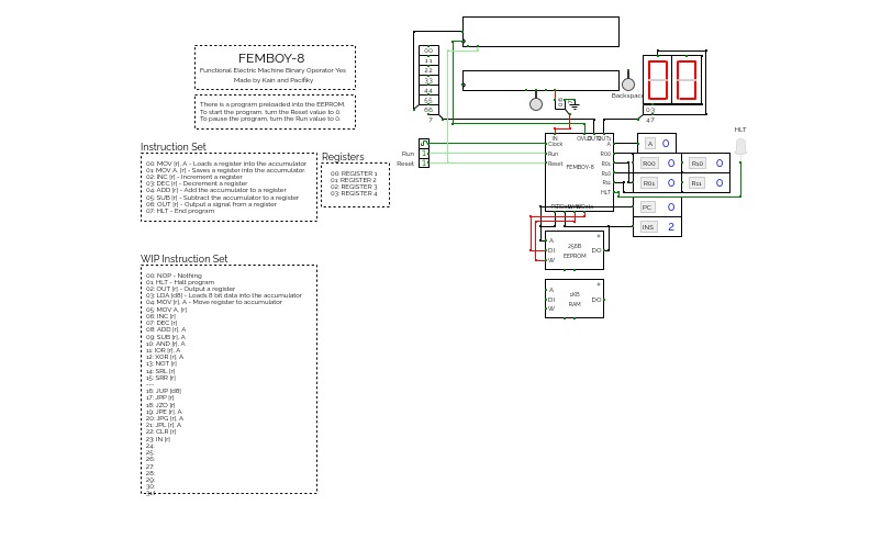

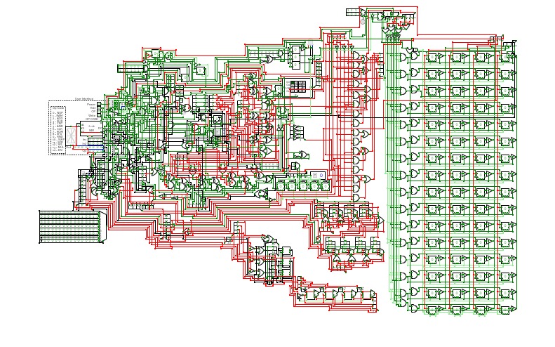
Functional Electronic Machine Binary Operator Yes - 8-bit cpu
This is a work in progress right now.
INSTRUCTION SET:
00: MOV [r], A - Loads a register into the accumulator.
01: MOV A, [r] - Saves a register into the accumulator.
02: INC [r] - Increment a register
03: DEC [r] - Decrement a register
04: ADD [r] - Add the accumulator to a register
05: SUB [r] - Subtract the accumulator to a register
06: OUT [r] - Output a signal from a register
07: HLT - End program
REGISTERS:
00: REGISTER 1
01: REGISTER 2
02: REGISTER 3
04: REGISTER 4
Update Notes:
Final design before update of is a.
To-Do:
Add WIP instructions
Add the accumulator to a register address
Increase amount of registers to 8
Add Ram manipulation instructions
Add Input to CPU
Add more operations to the ALU
Add ASCII i/o
Make a simple command line
Make an assember
Make a simple operating system for the cpu
Add rgb output
.jpg)
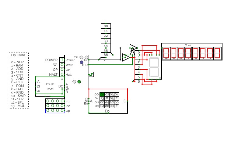
CTH-10 CPU
CTH-10 CPUThis is the CTH-10 CPU. By CrEePeRz24321. (most updated version of the CTH Series) This uses all binary to operate. First click on Power to start. Turn Op to 1 and double click the RAM. Then type in the Op code you want. Only put inputs and read outputs of the User Interface. Wait until the Red light turns Green then start. If you want to change operations, then turn Op to 1 and double click the RAM. Then type in the Op code you want. (If you use full screen, and it keeps on kicking you out when you type, click full screen and then look to the bottom right and press + or - and don't touch the full screen after that unless the RAM input kicks you out)
0 is No Operation - Inputs unavailable
1 is RAM - write the address into In1, write the number you want to store into In2 and press Write.
2 is ADD - write the first digit into In1, write the second digit into In2
3 is Subtract - write the first digit into In1, write the second digit into In2
4 is Counter - Inputs unavailable
5 is AND Gate - write the first digit into In1, write the second digit into In2
6 is a Clock - Inputs unavailable
7 is Accessing the ROM - Inputs unavailable
8 is Binary to Decimal converter
9 is Random Number - Inputs unavailable
10 is Not Gate - write the converting digit into In1
11 is Shift Right* - write the converting digit into In1, write the shift number into In2
12 is Shift Left* - write the converting digit into In1, write the shift number into In2
13 is Multiply - write the first digit into In1, write the second digit into In2
14 is Divide - write the first digit into In1, write the second digit into In2**
HALT is to halt operation
*when using shift the first 3 digits of Out will be nonfunctional
**when using divide the first 4 digits away from the CPU are remainders and the last 4 digits closest to the CPU are quotients.
(There is also a Computer version that doesn't get updated much.)
CTH-10
CTH-10This is the CTH-10 CPU. This uses all binary to operate. First click on Power to start. Turn Op to 1 and double click the RAM. Then type in the Op code you want. Only put inputs and read outputs of the User Interface. Wait until the Red light turns Green then start. If you want to change operations, then turn Op to 1 and double click the RAM. Then type in the Op code you want. (If you use full screen, and it keeps on kicking you out when you type, click full screen and then look to the bottom right and press + or - and don't touch the full screen after that unless the RAM input kicks you out)
0 is No Operation - Inputs unavailable
1 is RAM - write the address into In1, write the number you want to store into In2 and press Write.
2 is ADD - write the first digit into In1, write the second digit into In2
3 is Subtract - write the first digit into In1, write the second digit into In2
4 is Counter - Inputs unavailable
5 is AND Gate - write the first digit into In1, write the second digit into In2
6 is a Clock - Inputs unavailable
7 is Accessing the ROM - Inputs unavailable
8 is Binary to Decimal converter
9 is Random Number - Inputs unavailable
10 is Not Gate - write the converting digit into In1
11 is Shift Right* - write the converting digit into In1, write the shift number into In2
12 is Shift Left* - write the converting digit into In1, write the shift number into In2
13 is Multiply - write the first digit into In1, write the second digit into In2
HALT is to halt operation
*when using shift the first 3 digits of Out will be nonfunctional

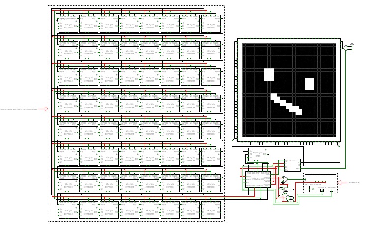

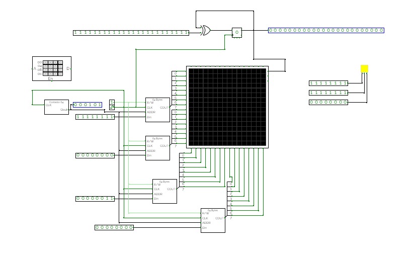
STRING 32000
STRING 32000Overview
The STRING32000 is a 32-bit CPU. It reads and executes each instruction in 1 clock cycle like all the old string CPUS. It has addressed pins and can modify its own code. While this CPU usually needs special external circuitry to interact with complex outputs like the RGB LED matrix, these external drive circuits are just meant to store the bitmap being drawn on the screen. The overall unspecialized nature of this CPU allows it to address up to input and output 65,536 32-bit pins.
Self-modifying code
Probably the most exciting feature about this CPU is that it can write to its main memory, which is where its program is stored. This means it supports self-modifying code. Self-modifying code is the ability for the computer to alter its own code that it is running. This was very very annoying to get working properly.
Executing values in registers as instructions
The second most exciting feature of this CPU is temporary instructions. This means that the CPU can make a very temporary custom instruction and execute it while it's in a register instead of being in something permanent like main memory, which is much safer since it decreases the risk of accidental corruption of the program. This was mildly annoying to get working.
Memory
There are two memories, which are both 32-bit with 16-bit addresses. The main memory sits outside the CPU and is nonvolatile and stores the program to execute and data to save. The second memory is also located outside the CPU and is volatile and used to store temporary values that are needed when operating, for example cursor position. For the safety of the program and the user's mental wellbeing, the CPU cannot activate the reset pin on the main memory to delete its own program all at once, since if there was some dumb bug and the CPU deleted data that the user didn't have a copy of, that could result in severe depression because of how heartbreaking it would be for an entire program that you didn't have a copy of to be deleted in the blink of an eye. So yeah, better to be safe than sorry.
About the morbidly obese main memory
Since the only memory that can be edited by circuitry and be used as permanent storage (EEPROM) only supports up to 10-bit addresses and STRING32000 supports up to 16-bit addresses, I have decided connect 64 EEPROM, which in total supports up to 16-bit addresses, fully utilizing the CPU's address space.
-----------------------
This computer currently only runs one program where you can make 32x32 pictures in black and white, but I'll make more programs for it in the future.
Controls for 32x32 painter:
keyboard controls: WASD to move cursor, Q to display an image, E to toggle pixel between black and white.
stepper: Use to select the picture slot. There is a face drawn in slot 0
PWR and EN: toggle both on to run. PWR is the main switch and EN freezes the clock when disabled.
-----------------------
CREDITS:
Credit to Sanderokian Stfetoneri (author of Femto) for the fast clock circuit
FORK FOR BEST USER EXPIERIENCE
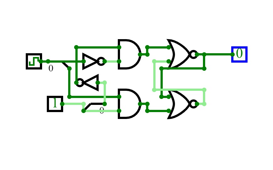
Gated-Latch
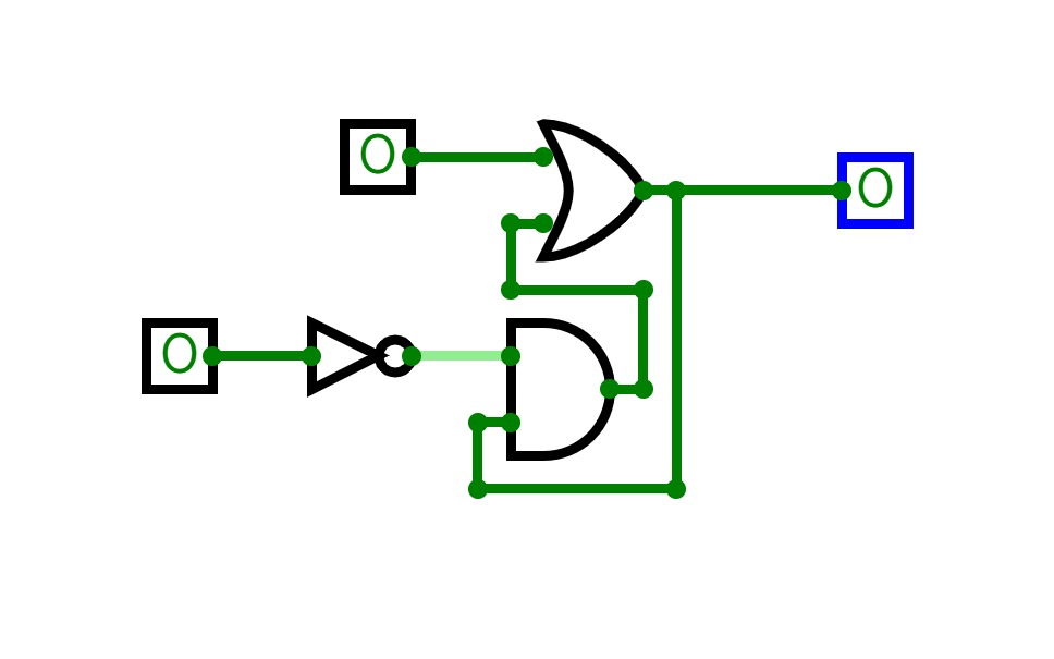
Gated-LatchA simple Gated-Latch system.
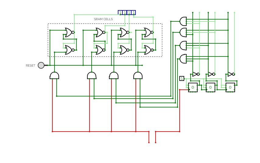
Static serial RAM with serial input
Static serial RAM with serial inputin this project i made a 4 bit RAM which can be written through serial communication(SCL - clock and SDA- data(1 or 0)) then a rising edge of a square wave is detected in the SCL pin, the enable pin of the SRAM cells are enabled in an order according to each clock pulse. simultaneously a data is given through the SDA pin according to the Nth clock pulse to the Nth SRAM cell.
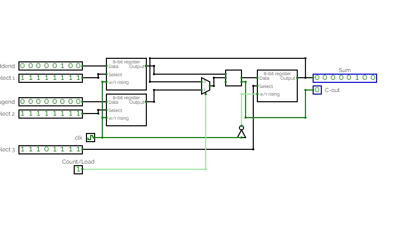
Adjustable 8-bit adder which either loads values from two different registers into an 8-bit adder or sequentially adds the current output value of the adder to the value stored in the first register. Practice for RAM unit application, register creation and organization, bit splitting and compression, and sequential logic.


