

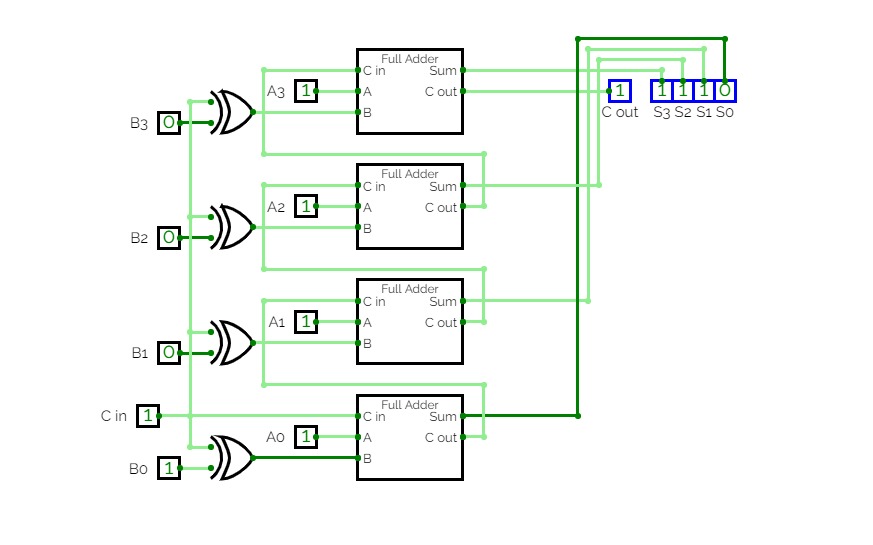
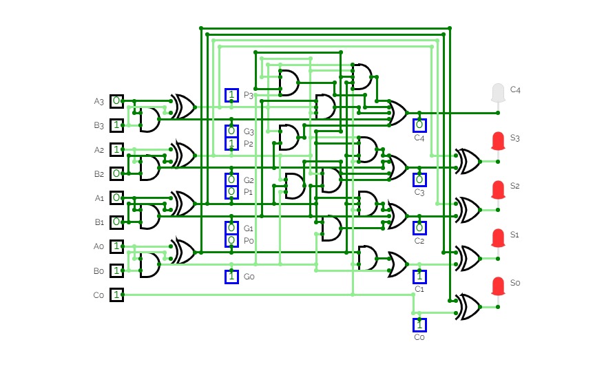
4-bit full adder
4-bit full adder
4-bit Odd parity bit generator
4-bit Odd parity bit generator4-bit Odd parity bit generator using XOR and XNOR
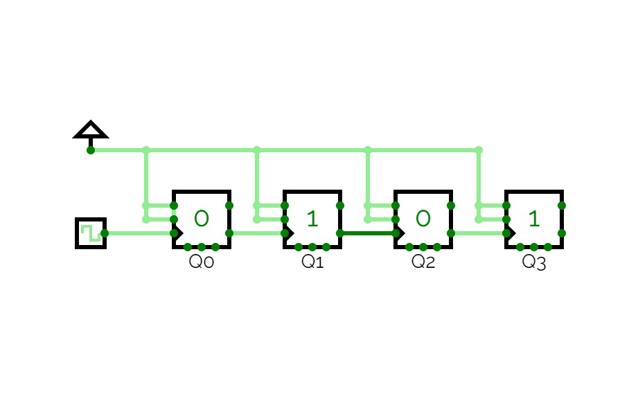
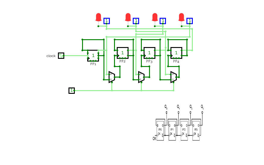
4 bit Asynchronous Counter
4 bit Asynchronous Counter4 bit Asynchronous Counter using JK FlipFlops
Async Counter
Async Counter4 Bit Asynchronous Counter using JK Flip-FLop

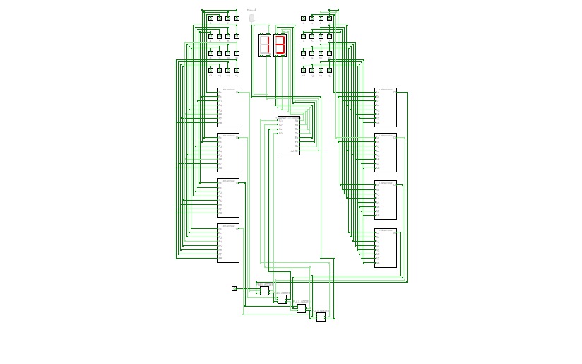

4-bit Adder
4-bit AdderThe 4-bit adder which can do math on 4-bit integers and display on 2 7-segment LEDs.
This project is owned by Lu Xuan Minh - student of HCMUT.
Everyone can fork my project for the purpose of studying and researching.
Thank you for your viewing!
Lu Xuan Minh
Email: [email protected]
4-bit asyncronous counter
4-bit asyncronous counter4-bit Adder
4-bit Adder4-bit Adder with 7 segment display
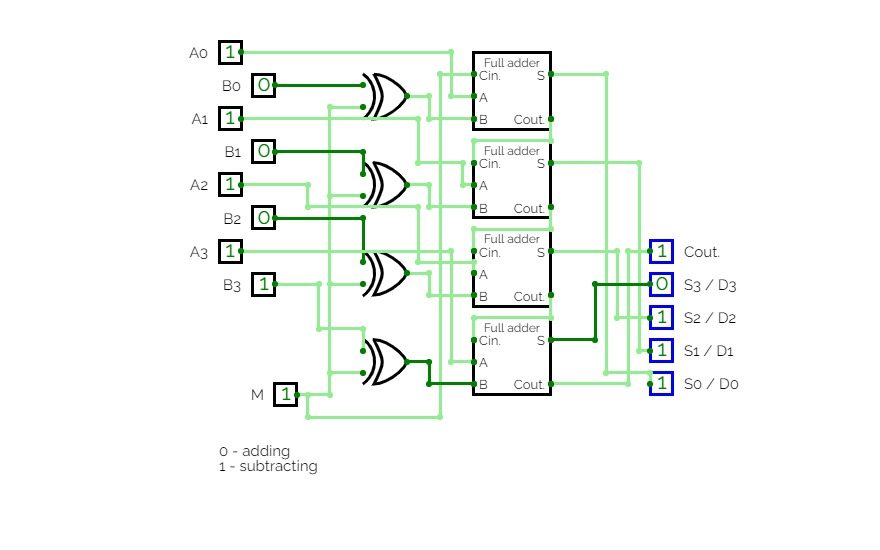
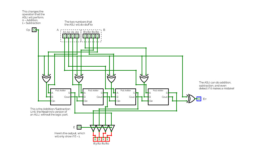
4 bit adder subtractor
4 bit adder subtractorThis is a 4 bit adder.
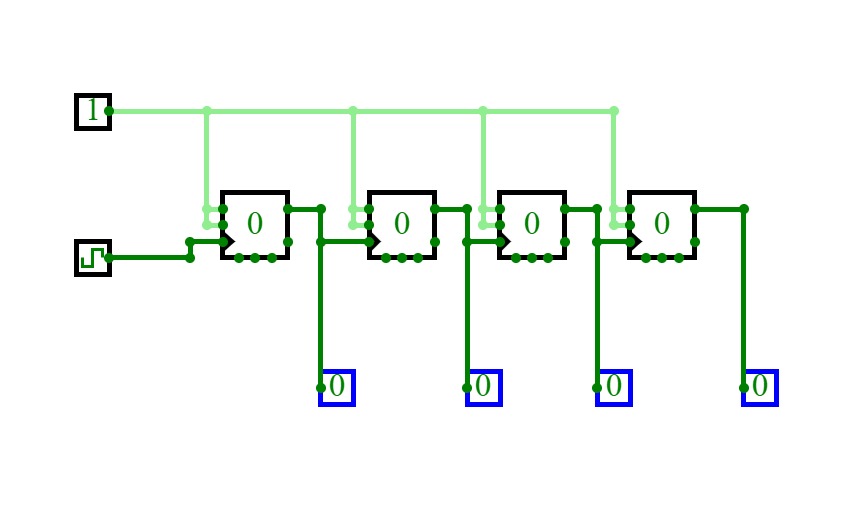
4BitDownCounterDFlipFlop
4BitDownCounterDFlipFlop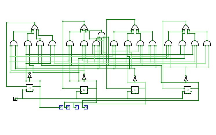
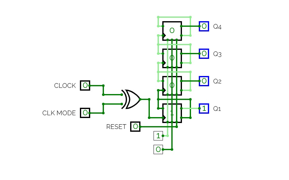
4Bit_DownUpCounter
4Bit_DownUpCounterCount from 9-8-7-6-5-4-3-2-1-0-10-11-12
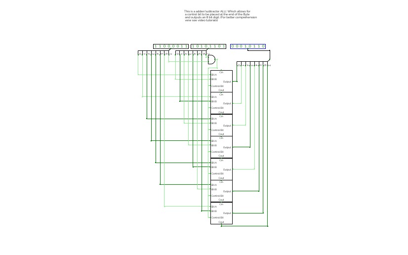
Features a single-bit adder and subtractor as well as a combination of the two. Also showcases a 4-bit adder/subtractor and an 8-bit ALU adder subtractor.
(If anything in the description is wrong please feel free to say so in the comments.

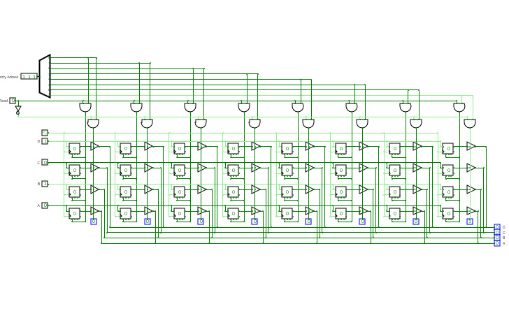
4-bit Bidirectional Shift Register with Parallel Load
4-bit Bidirectional Shift Register with Parallel Load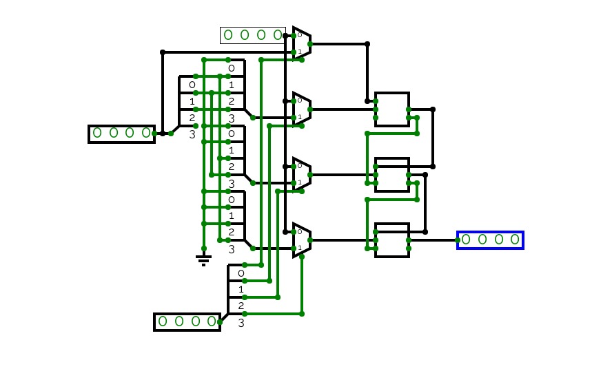

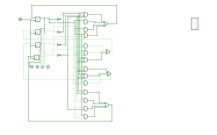
4-bit Multiplier (No Overflow)
4-bit Multiplier (No Overflow)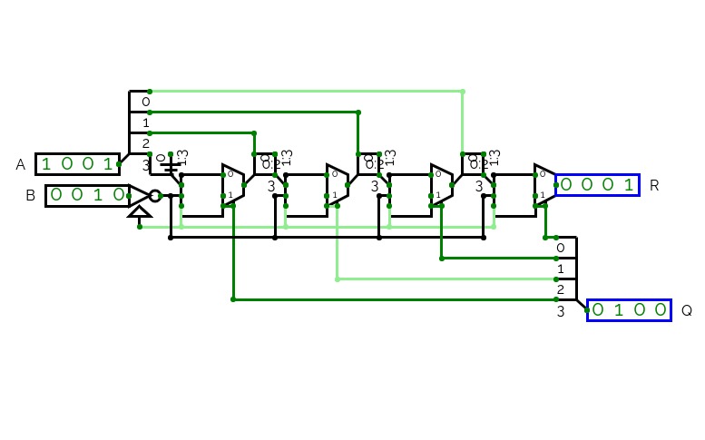
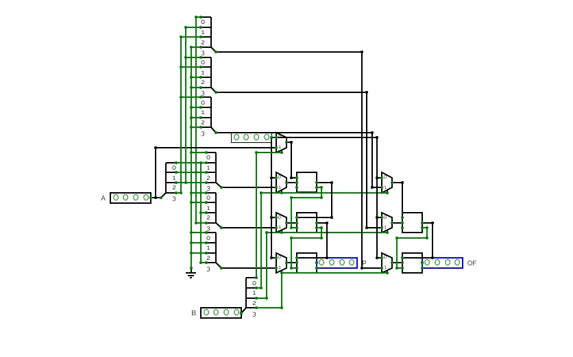
4-bit Multiplier
4-bit MultiplierYay overflow
.jpg)
CTH-10
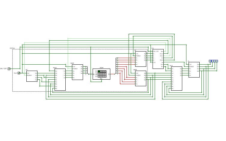
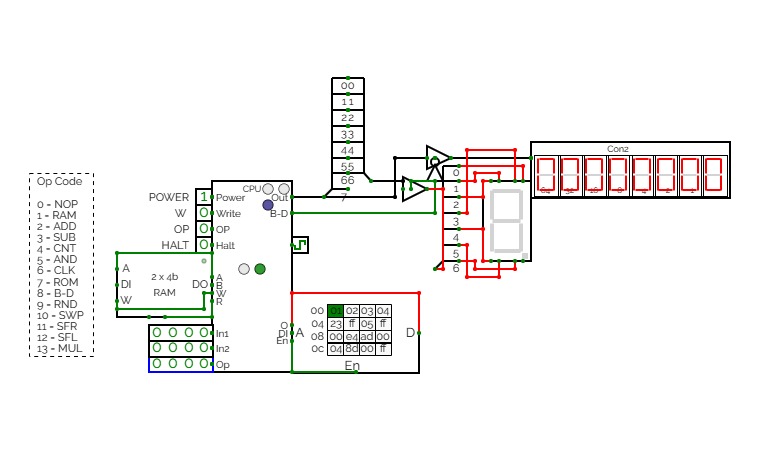
CTH-10This is the CTH-10 CPU. This uses all binary to operate. First click on Power to start. Turn Op to 1 and double click the RAM. Then type in the Op code you want. Only put inputs and read outputs of the User Interface. Wait until the Red light turns Green then start. If you want to change operations, then turn Op to 1 and double click the RAM. Then type in the Op code you want. (If you use full screen, and it keeps on kicking you out when you type, click full screen and then look to the bottom right and press + or - and don't touch the full screen after that unless the RAM input kicks you out)
0 is No Operation - Inputs unavailable
1 is RAM - write the address into In1, write the number you want to store into In2 and press Write.
2 is ADD - write the first digit into In1, write the second digit into In2
3 is Subtract - write the first digit into In1, write the second digit into In2
4 is Counter - Inputs unavailable
5 is AND Gate - write the first digit into In1, write the second digit into In2
6 is a Clock - Inputs unavailable
7 is Accessing the ROM - Inputs unavailable
8 is Binary to Decimal converter
9 is Random Number - Inputs unavailable
10 is Not Gate - write the converting digit into In1
11 is Shift Right* - write the converting digit into In1, write the shift number into In2
12 is Shift Left* - write the converting digit into In1, write the shift number into In2
13 is Multiply - write the first digit into In1, write the second digit into In2
HALT is to halt operation
*when using shift the first 3 digits of Out will be nonfunctional
CTH-10 CPU
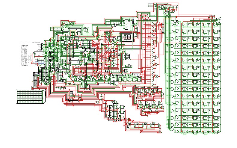
CTH-10 CPUThis is the CTH-10 CPU. By CrEePeRz24321. (most updated version of the CTH Series) This uses all binary to operate. First click on Power to start. Turn Op to 1 and double click the RAM. Then type in the Op code you want. Only put inputs and read outputs of the User Interface. Wait until the Red light turns Green then start. If you want to change operations, then turn Op to 1 and double click the RAM. Then type in the Op code you want. (If you use full screen, and it keeps on kicking you out when you type, click full screen and then look to the bottom right and press + or - and don't touch the full screen after that unless the RAM input kicks you out)
0 is No Operation - Inputs unavailable
1 is RAM - write the address into In1, write the number you want to store into In2 and press Write.
2 is ADD - write the first digit into In1, write the second digit into In2
3 is Subtract - write the first digit into In1, write the second digit into In2
4 is Counter - Inputs unavailable
5 is AND Gate - write the first digit into In1, write the second digit into In2
6 is a Clock - Inputs unavailable
7 is Accessing the ROM - Inputs unavailable
8 is Binary to Decimal converter
9 is Random Number - Inputs unavailable
10 is Not Gate - write the converting digit into In1
11 is Shift Right* - write the converting digit into In1, write the shift number into In2
12 is Shift Left* - write the converting digit into In1, write the shift number into In2
13 is Multiply - write the first digit into In1, write the second digit into In2
14 is Divide - write the first digit into In1, write the second digit into In2**
HALT is to halt operation
*when using shift the first 3 digits of Out will be nonfunctional
**when using divide the first 4 digits away from the CPU are remainders and the last 4 digits closest to the CPU are quotients.
(There is also a Computer version that doesn't get updated much.)
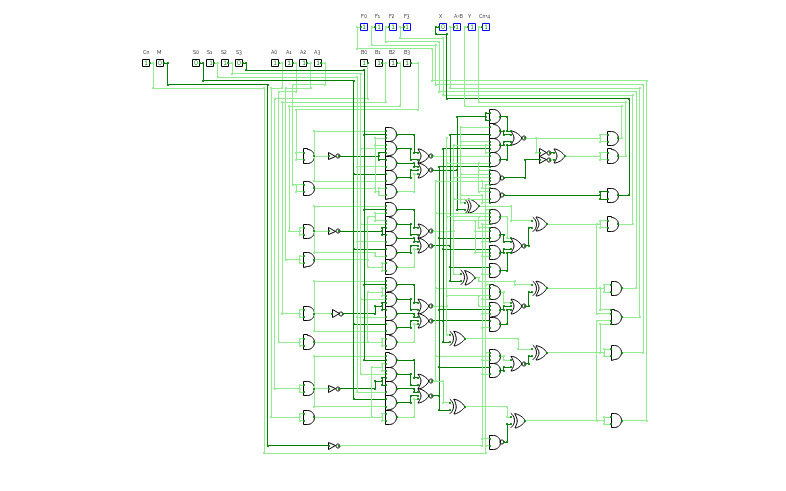
Texas Instruments 74181
Texas Instruments 74181This is a recreation of the eponymous TI circuit for examining it's function. This circuit is an exact copy of the TI chip but with some IO circuitry for visualization. This schematic was created with the intention of using it to debug an emulated version created in a physics sandbox game, Phyzios Studio Pro.


