
May Thet Htar Lwin
May Thet Htar Lwin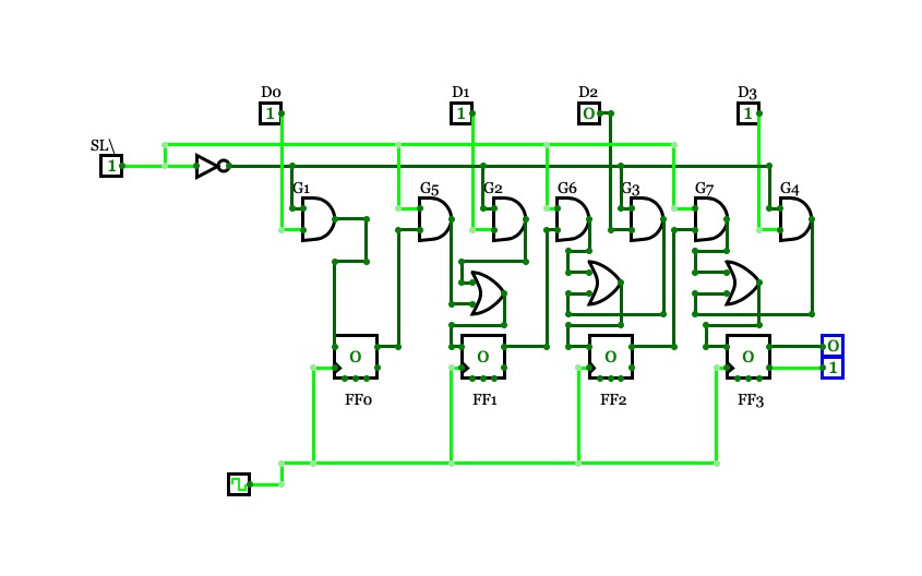
John D/Lab 17
John D/Lab 17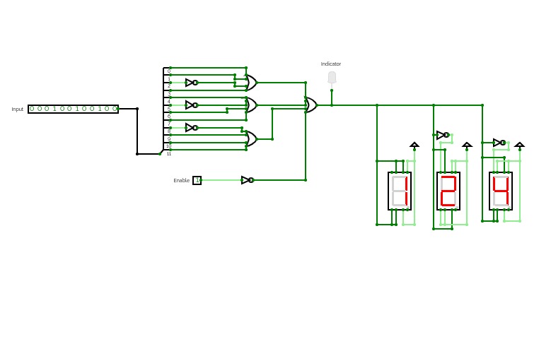
Roll Number
Roll Number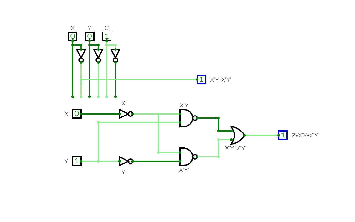
Combinational Circuits
Combinational CircuitsCombinational Circuits :-
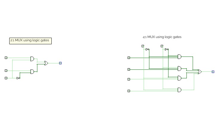
Combinational circuit is a circuit in which we combine the different gates in the circuit, for example encoder, decoder, multiplexer and demultiplexer. Some of the characteristics of combinational circuits are following −
- The output of combinational circuit at any instant of time, depends only on the levels present at input terminals.
- The combinational circuit do not use any memory. The previous state of input does not have any effect on the present state of the circuit.
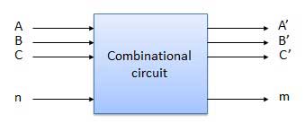
- A combinational circuit can have an n number of inputs and m number of outputs.
Block diagram
ASSIGNMENT :-
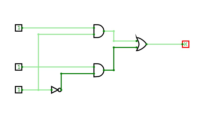
In this assignment I am working on designing and simulating the given boolean function ( Z=X'Y+X'Y' ).
- Truth table for given function :

- Design of circuit using gates :

* Formed using manual inputs and outputs using simulator.
- Circuit on simulation :

* Formed using combinational analysis tool in simulator.
Practical 2
Practical 2Logic Gates :-
Logic gates are the basic building blocks of any digital system. It is an electronic circuit having one or more than one input and only one output. The relationship between the input and the output is based on a certain logic.
Logic gates are named as :
- AND Gate
- OR Gate
- NOR Gate
- NAND Gate
- XOR Gate
- XNOR Gate
- NOT Gate
ASSIGNMENT :
In the given assignment I have to verify all the logic gates and hence I had used digital led for it.
- Digital LED :
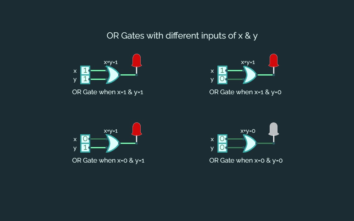
Digital LED is used for verification of circuit in digital electronics. It glows when circuit gives a true value and do not glows when the value is false.
In this assignment when the value will be true i.e., output will be 1 LED will glow with red color and else it will be shown in a white transparent color.
- Truth table & verification images of different gates :-
- AND Gate :


2. OR Gate :


3. NOT Gate:


4. NAND Gate :


5. NOR Gate:


6. XOR Gate:


7. XNOR Gate:


** All the diagrams and truth tables I had used above is formed using tools provided in simulator.
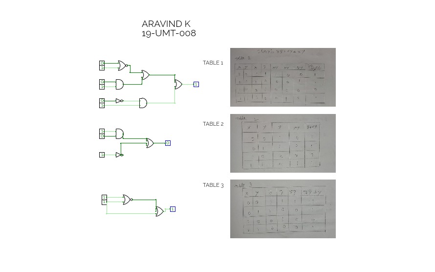
LOGIC GATES ASSIGNMENT
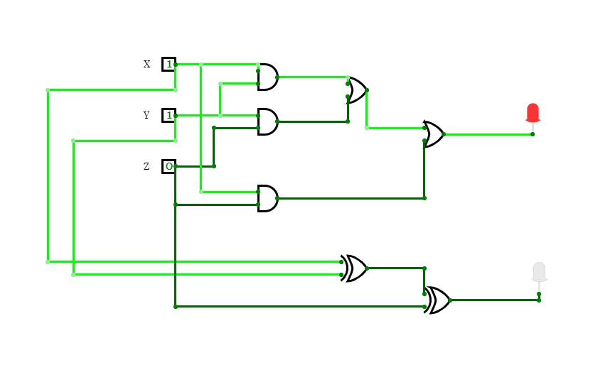
LOGIC GATES ASSIGNMENTLogic gate Circuits for the given expression has been verified with the truth table.
F(X,Y) = X'Y' + XY + X'Y is table 1.
The above expression can be simplified as the following two expressions.
F(X,Y) = X' + XY is table 2.
F(X,Y) = X'Y' + Y is table 3.
DLD Practical Assignment
DLD Practical AssignmentAbdullah El-Nahas
T-11
52-4957
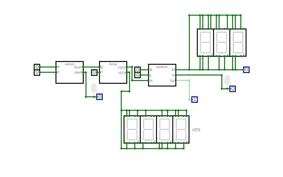
Sensor and Sanitizer
Sensor and SanitizerIt is a combination of temperature scanner and auto hand sanitizer.
2.23A
2.23A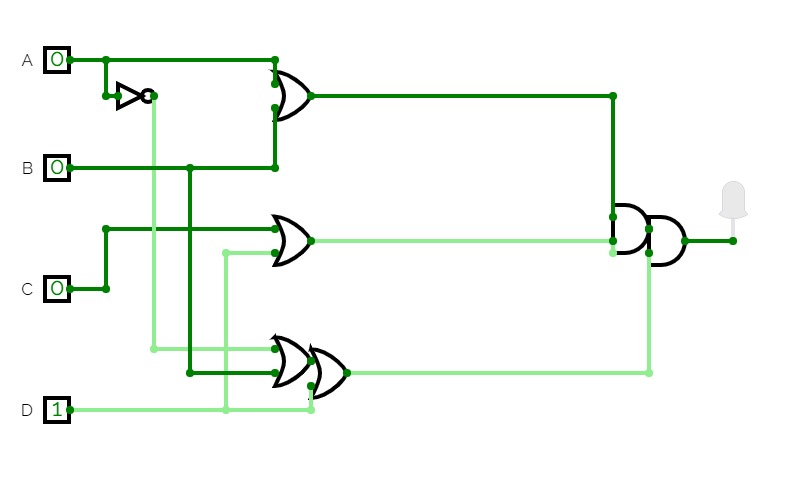
2.23B
2.23B
2.23C
2.23C
2.23D
2.23D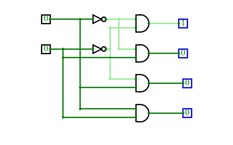
Assignment
Assignment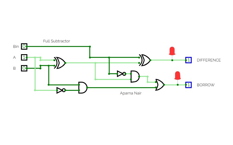
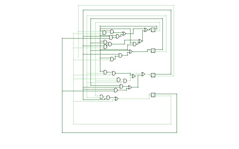
Aparna Nair/NO.4 ADDERS AND SUBTRACTORS
Aparna Nair/NO.4 ADDERS AND SUBTRACTORS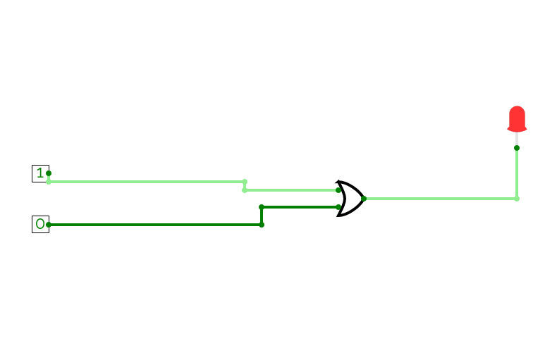
Led light
Led lightIt's for lab

HPC0_Assignment1
HPC0_Assignment1HPC0 Assignment 1
Manuel Kieselbach
Assignment 2
Assignment 2Assignment 2
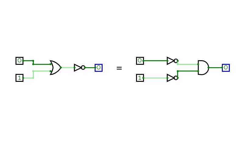
(a) Implement all the basic logic gates using NAND gates only.
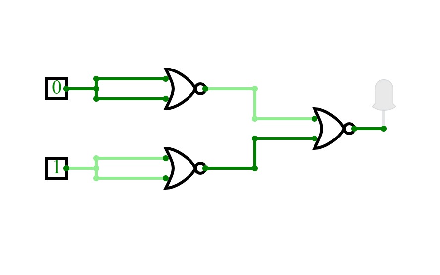
(b) Implement all the basic logic gates using NOR gates only.
Lab 3
Lab 3
22U02050
22U02050
4 bit circuit for binary to Gray code
4 bit circuit for binary to Gray code
Binary to graycode conversion
Binary to graycode conversionconversion of binary to graycode